


OWNER‘S MANUAL BEDIENUNGSANLEITUNG MODE D‘EMPLOI

CONTENTS
IMPORTANT SAFETY INSTRUCTIONS ....................... |
3 |
IMPORTANT SERVICE INSTRUCTIONS ....................... |
3 |
DESCRIPTION ....................... |
4 |
UNPACKING & WARRANTY ....................... |
4 |
CONTROLS ....................... |
5 |
INPUT / OUTPUT ....................... |
5 |
LEVEL ....................... |
5 |
MODE ....................... |
5 |
STATUS ANZEIGEN ....................... |
6 |
POWER SCHALTER ....................... |
6 |
NETZEINGANG ....................... |
6 |
SPECIFICATIONS /TECHNISCHE DATEN ....................... |
19 |
DIMENSIONS / ABMESSUNGEN ....................... |
20 |
BLOCK DIAGRAM ....................... |
21 |
INHALT
WICHTIGE SICHERHEITSHINWEISE ....................... |
9 |
WICHTIGE SERVICEHINWEISE ....................... |
9 |
BESCHREIBUNG ....................... |
10 |
AUSPACKEN & GARANTIE ....................... |
10 |
BEDIENELEMENTE ....................... |
11 |
INPUT / OUTPUT ....................... |
11 |
LEVEL ....................... |
11 |
MODE ....................... |
11 |
STATUS ANZEIGEN ....................... |
12 |
POWER SCHALTER ....................... |
12 |
NETZEINGANG ....................... |
12 |
SPECIFICATIONS /TECHNISCHE DATEN ....................... |
19 |
DIMENSIONS / ABMESSUNGEN ....................... |
20 |
BLOCK DIAGRAM ....................... |
21 |
MATIÈRES
IMPORTANTES INFORMATIONS DE SÉCURITÉ ....................... |
15 |
INSTRUCTIONS DE RÉPARATION IMPORTANTES ....................... |
15 |
DESCRIPTION ....................... |
16 |
DÉBALLAGE ET GARANTIE ....................... |
16 |
CONTROLES ....................... |
17 |
ENTRÉE (INPUT / SORTIE (OUTPUT ....................... |
17 |
NIVEAU (LEVEL ....................... |
17 |
MODE ....................... |
17 |
CONTROLES ....................... |
18 |
INTERRUPTEUR SECTEUR (POWER) ....................... |
18 |
SPECIFICATIONS ....................... |
19 |
DIMENSIONS ....................... |
20 |
BLOCK DIAGRAM ....................... |
21 |
2
IMPORTANT SAFETY INSTRUCTIONS
1.Read these instructions.
2.Keep these instructions.
The lightning flash with arrowhead symbol, within an equilateral triangle is intended to alert the user to the presence of uninsulated „dangerous voltage“ within the product’s enclosure that may be of sufficient magnitude to constitute a risk of electric shock to persons
The exclamation point within an equilateral triangle is intended to alert the user to the presence of important operating and maintance (servicing) instructions in the literature accompanying the appliance.
3.Heed all warnings.
4.Follow all instructions.
5.Do not use this apparatus near water. Do not expose this apparatus to dripping or splashing and ensure that no objects filled with liquids, such as vases, are placed on this apparatus.
6.Clean only with a dry cloth.
7.Do not block any of the ventilation openings. Install in accordance with the manufactures instructions.
8.Do not install near any heat sources such as radiators, heat registers, stoves, or other apparatus (including amplifiers) that produce heat.
9.Only use attachments/accessories specified by the manufacturer.
10.Refer all servicing to qualified service personnel. Servicing is required when the apparatus has been damaged in any way, such as power-supply cord or plug is damaged, liquid has been spilled or objects have fallen into the apparatus, the apparatus has been exposed to rain or moisture, does not operate normally, or has been dropped
11.To completely disconnect mains power from this apparatus, the power supply cord must be unplugged.
Caution: Do not exceed the marked rating of the Mains Output.
Example: If each additional unit is rated 3A, a maximum of 3 units can be connected for a total of 9A.
For US and CANADA only:
1.Do not defeat the safety purpose of the grounding-type plug. A grounding type plug has two blades and a third grounding prong.The wide blade or the third prong are provided for your safety.When the provided plug does not fit into your outlet, consult an electrican for replacement of the absolete outlet.
2.Protect the power cord from being walked on or pinched particularly at plugs, convenience receptacles, and the point where they exit the apparatus.
3.Unplug this apparatus during lightning storms or when unused for long periods of time.
IMPORTANT SERVICE INSTRUCTIONS
CAUTION: These servicing instructions are for use by qualified personnel only. To reduce the risk of electric shock, do not perform any servicing other than that ontained in the Operating Instructions unless you are qualified to do so. Refer all ervicing to qualified service personnel.
1.Security regulations as stated in the EN 60065 (VDE 0860 / IEC 65) and the CSA E65 - 94 have to be obeyed when servicing the appliance
2.Use of a mains separator transformer is mandatory during maintenance while the appliance is opened, needs to be operated and is connected to the mains
3.Switch off the power before retrofitting any extensions, changing the mains voltage or the output voltage.
4.The minimum distance between parts carrying mains voltage and any accessible metal piece (metal enclosure), respectively between the mains poles has to be 3 mm and needs to be minded at all times. The minimum distance between parts carrying mains voltage and any switches or breakers that are not connected to the mains (secondary parts) has to be 6 mm and needs to be minded at all times.
5.Replacing special components that are marked in the circuit diagram using the security symbol (Note) is only rmissible when using original parts.
6.Altering the circuitry without prior consent or advice is not legitimate.
7.Any work security regulations that are applicable at the location where the appliance is being serviced have to be strictly obeyed.This applies also to any regulations about the work place itself.
8.All instructions concerning the handling of MOS - circuits have to be observed.
NOTE: |
SAFETY COMPONENT ( MUST BE REPLACED BY ORIGINAL PART ) |
3

DESCRIPTION
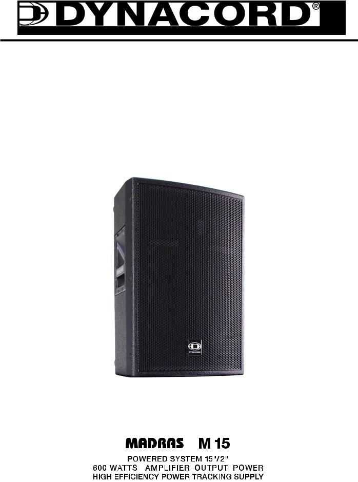
Congratulations!Your new DYNACORD MADRAS M15 is an active loudspeaker cabinet incorporating state-of-the art technology.
The MADRAS M15 mid/high frequency range is reproduced by an Electro-Voice ND6 neodymium driver with 3” voice-coil while an Electro-Voice EVX155 transmits the bass frequency range. The integrated power amplifier provides discrete low and high range channels, an integrated active frequency crossover (Linkwitz-Riley, 124Hz, 24dB/octave) and signal processing. Selecting “FULL-RANGE” or “MID-HIGH” operation is possible via switch button.
A high-efficiency Class-H power amplifier provides the low range signal. Consequential use of Class-H technology reduces power dissipation, power consumption as well as the power amp’s weight noticeably. High range audio signal amplification is realized via a separate power amplifier. Both power amp blocks are convection-cooled, resulting in no disturbing noise from running fans.
The power output capacity of 600W (460W + 140W) allows peak sound pressure levels of more than 128dB at lowest distortion rates. The achievable coverage range approximately doubles the scope of conventional passive loudspeaker systems. The wide radiation angle of 80°x 55° eliminates alignment problems inherent to narrow-angled speaker systems.
The MADRAS M15 has an extremely linear frequency response. Horizontal and vertical radiation characteristics are outstandingly smooth, which makes the MADRAS M15 resistant against acoustical feedback and therefore especially suitable for high-power monitoring applications. The fully electronic THERMAL PROTECTION prevents the transducers from being damaged by thermal overload. That’s what makes the MADRAS M15 equally suitable for a wide range of demanding applications in the rental business.
The integrated rigging-rail and adjustment-bracket allow for the trouble-free use of the MADRAS M15 in flown applications.The asymmetric birch multi-plywood enclosure is sealed with black, extremely shockresistant structural lacquer finish. A robust, powder-coated steel grille protects the transducers against mechanical damage. Mains connection is provided via lockable PowerCon connector. Connecting an additional cabinet is possible via PowerCon mains output.Audio signal connection is provided via XLRFtype connector. An additional XLRF-type connector allows feeding the signal to another cabinet.
Two stable carrying handles and the integrated aluminum pole-mount allow for comfortable transport and trouble-free installation.
UNPACKING & WARRANTY
Open the packaging and carefully take out the MADRAS M15. In addition to the appliance itself and this owner’s manual, the package also includes mains cord, level control cover and warranty certificate. Please make sure to keep warranty certificate and original invoice, stating the date of purchase, at a safe place.
4
CONTROLS
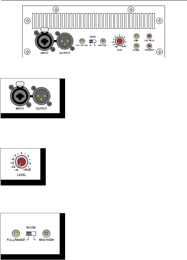
INPUT
Electronically balanced input for the connection of high-level signal sources like mixing consoles or signal processors. Connections can be established using phone or alternatively XLR-type connectors.
Caution: Preventing the occurrence of spurious noise. Prior to connecting/disconnecting the input, set the level control to its counterclockwise stop.
OUTPUT
This connector is connected in parallel to the input allowing the through connection of the input audio signal.
LEVEL
dB-scaled level control for adjusting the power amp’s overall amplification.To prevent distortion and clipping of pre-linked mixing consoles, the control should generally be set to a value between 0dB and +6dB.
MODE
This switch allows selecting the operation mode of the M15. The cabinet’s internal active frequency crossover is automatically deactivated when set to FULLRANGE. The loudspeaker system transmits the entire frequency range. Setting the switch to the position MID-HIGH activates an active frequency crossover with 124Hz crossover frequency, so that only the audio signal’s mid-high range is transmitted. When using a M15 in combination with a M18 subwoofer, selecting MID-HIGH is generally recommended, to ensure linear frequency response of the M15/M18 combination.
UsingthecabinetinMID-Highmodeinmonitoringapplications may be favorable for attenuating the reproduction of low frequency signals.
5
CONTROLS
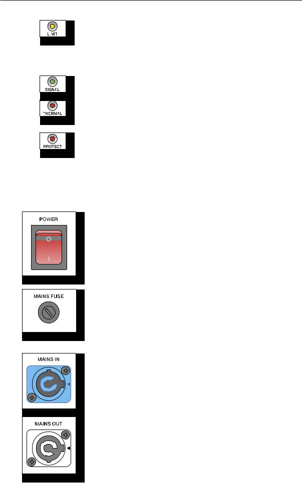
LIMIT brief blinking indicates that the power amplifier is operated at its limits. Short-term blinking is uncritical, because the integrated limiter compensates minor distortion. Constant lighting of the LED indicates that the sound is negatively affected. Reducing the output volume is strongly recommended.
SIGNAL indicates the presence of an input signal.
THERMAL lights, when the power amp’s output power is reduced to prevent thermal overload.
PROTECTION lights, when one of the power amp’s comprehensive protections against e.g. thermal overload, HF or DC at the output, and Back-EMF has been activated.The speaker outputs are deactivated and the input gain is reduced when in Protect Mode, to protect the power amplifier from damage.
The PROTECT LED lights for approximately 2 seconds during power-on operation.This is normal, indicating that all protections are working.
POWER-switch
Mains switch for powering the appliance on or off.With the power amplifier being switched on, the mains switch is backlit. If, after switching the power on, the switch is not backlit, please first check whether the mains cord is correctly connected. In case the cord has been connected correctly and the switch still fails to light (no function), please contact your specialist dealer.
MAINS FUSE
Under normal circumstance the mains fuse only blows in case of failure. Always use an identical type with the same current, voltage and blow characteristics when replacing the mains fuse. If the mains fuse blows more often, please contact your specialist dealer.
MAINS IN
Mains connector is carried out as PowerCon-type socket. A fitting mains cord (5m) with PowerCon-type plug is supplied.
MAINS OUT
This PowerCon mains out socket allows the connection of additional MADRAS cabinets, e.g. M15 or M18, using special cords (PC150 or PC800).
To prevent mains n etwork overload, connecting more than three MADRAS cabinets to a single mains outlet (10A-16A) is not recommended.
6
BEDIENUNGSANLEITUNG

INHALT
WICHTIGE SICHERHEITSHINWEISE ....................... |
9 |
WICHTIGE SERVICEHINWEISE ....................... |
9 |
BESCHREIBUNG ....................... |
10 |
AUSPACKEN & GARANTIE ....................... |
10 |
BEDIENELEMENTE ....................... |
11 |
INPUT / OUTPUT ....................... |
11 |
LEVEL ....................... |
11 |
MODE ....................... |
11 |
STATUS ANZEIGEN ....................... |
12 |
POWER SCHALTER ....................... |
12 |
NETZEINGANG ....................... |
12 |
SPECIFICATIONS /TECHNISCHE DATEN ....................... |
19 |
DIMENSIONS / ABMESSUNGEN ....................... |
20 |
BLOCK DIAGRAM ....................... |
21 |
8
 Loading...