


 Loading...
OWNER’S MANUAL BEDIENUNGSANLEITUNG MODE D’EMPLOI
H 2500 H 5000
PowerH SERIES

PowerH SERIES
CONTENTS
Introduction . . . . . . . . . . . . . . . . . . . . . . . . . . . . . . . . . . . . . . . . . . . . . . . . . . . . . . . . . . . . . . . . . 5
Welcome . . . . . . . . . . . . . . . . . . . . . . . . . . . . . . . . . . . . . . . . . . . . . . . . . . . . . . . . . . . . . . 5 Unpacking and Inspection . . . . . . . . . . . . . . . . . . . . . . . . . . . . . . . . . . . . . . . . . . . . . . . . . 5 Scope of Delivery and Warranty . . . . . . . . . . . . . . . . . . . . . . . . . . . . . . . . . . . . . . . . . . . . . 5 Features and Description . . . . . . . . . . . . . . . . . . . . . . . . . . . . . . . . . . . . . . . . . . . . . . . . . . 6 Responsibility of the User . . . . . . . . . . . . . . . . . . . . . . . . . . . . . . . . . . . . . . . . . . . . . . . . . . 6
Installation . . . . . . . . . . . . . . . . . . . . . . . . . . . . . . . . . . . . . . . . . . . . . . . . . . . . . . . . . . . . . . . . . . 7
Controls, Indicators and Connections . . . . . . . . . . . . . . . . . . . . . . . . . . . . . . . . . . . . . . . . 7 Operating Voltage . . . . . . . . . . . . . . . . . . . . . . . . . . . . . . . . . . . . . . . . . . . . . . . . . . . . . . . 9 Mains Switch . . . . . . . . . . . . . . . . . . . . . . . . . . . . . . . . . . . . . . . . . . . . . . . . . . . . . . . . . . . 11 Mounting . . . . . . . . . . . . . . . . . . . . . . . . . . . . . . . . . . . . . . . . . . . . . . . . . . . . . . . . . . . . . . . 12 Ventilation . . . . . . . . . . . . . . . . . . . . . . . . . . . . . . . . . . . . . . . . . . . . . . . . . . . . . . . . . . . . . . 13 Groundlift . . . . . . . . . . . . . . . . . . . . . . . . . . . . . . . . . . . . . . . . . . . . . . . . . . . . . . . . . . . . . . 13 Indication of the Operation Mode . . . . . . . . . . . . . . . . . . . . . . . . . . . . . . . . . . . . . . . . . . . . 14 Selecting the Mode Of Operation . . . . . . . . . . . . . . . . . . . . . . . . . . . . . . . . . . . . . . . . . . . . 14
Operation . . . . . . . . . . . . . . . . . . . . . . . . . . . . . . . . . . . . . . . . . . . . . . . . . . . . . . . . . . . . . . . . . . . 19
Volume Control . . . . . . . . . . . . . . . . . . . . . . . . . . . . . . . . . . . . . . . . . . . . . . . . . . . . . . . . . . 19 Graphical LC display . . . . . . . . . . . . . . . . . . . . . . . . . . . . . . . . . . . . . . . . . . . . . . . . . . . . . 19 Indications . . . . . . . . . . . . . . . . . . . . . . . . . . . . . . . . . . . . . . . . . . . . . . . . . . . . . . . . . . . . . 30 Fan Cooling . . . . . . . . . . . . . . . . . . . . . . . . . . . . . . . . . . . . . . . . . . . . . . . . . . . . . . . . . . . . 31 Air Filter . . . . . . . . . . . . . . . . . . . . . . . . . . . . . . . . . . . . . . . . . . . . . . . . . . . . . . . . . . . . . . . 31 Protections . . . . . . . . . . . . . . . . . . . . . . . . . . . . . . . . . . . . . . . . . . . . . . . . . . . . . . . . . . . . . 32
Options . . . . . . . . . . . . . . . . . . . . . . . . . . . . . . . . . . . . . . . . . . . . . . . . . . . . . . . . . . . . . . . . . . . . 35
RCM-26 . . . . . . . . . . . . . . . . . . . . . . . . . . . . . . . . . . . . . . . . . . . . . . . . . . . . . . . . . . . . . . . 35
INHALT
Einführung . . . . . . . . . . . . . . . . . . . . . . . . . . . . . . . . . . . . . . . . . . . . . . . . . . . . . . . . . . . . . . . . . 48
Willkommen . . . . . . . . . . . . . . . . . . . . . . . . . . . . . . . . . . . . . . . . . . . . . . . . . . . . . . . . . . . . 48 Auspacken und Inspektion . . . . . . . . . . . . . . . . . . . . . . . . . . . . . . . . . . . . . . . . . . . . . . . . . 48 Lieferumfang und Garantie . . . . . . . . . . . . . . . . . . . . . . . . . . . . . . . . . . . . . . . . . . . . . . . . . 48 Eigenschaften & Beschreibung . . . . . . . . . . . . . . . . . . . . . . . . . . . . . . . . . . . . . . . . . . . . . 49 Verantwortung des Betreibers . . . . . . . . . . . . . . . . . . . . . . . . . . . . . . . . . . . . . . . . . . . . . . 49
Installation . . . . . . . . . . . . . . . . . . . . . . . . . . . . . . . . . . . . . . . . . . . . . . . . . . . . . . . . . . . . . . . . . . 50
Bedienelemente, Anzeigen und Anschlüsse . . . . . . . . . . . . . . . . . . . . . . . . . . . . . . . . . . . 50 Betriebsspannung . . . . . . . . . . . . . . . . . . . . . . . . . . . . . . . . . . . . . . . . . . . . . . . . . . . . . . . 52 Netzschalter . . . . . . . . . . . . . . . . . . . . . . . . . . . . . . . . . . . . . . . . . . . . . . . . . . . . . . . . . . . . 54 Einbau . . . . . . . . . . . . . . . . . . . . . . . . . . . . . . . . . . . . . . . . . . . . . . . . . . . . . . . . . . . . . . . . 55 Kühlung . . . . . . . . . . . . . . . . . . . . . . . . . . . . . . . . . . . . . . . . . . . . . . . . . . . . . . . . . . . . . . . 56 Groundlift . . . . . . . . . . . . . . . . . . . . . . . . . . . . . . . . . . . . . . . . . . . . . . . . . . . . . . . . . . . . . . 56 Anzeige der Betriebsart . . . . . . . . . . . . . . . . . . . . . . . . . . . . . . . . . . . . . . . . . . . . . . . . . . . 57 Wahl der Betriebsart . . . . . . . . . . . . . . . . . . . . . . . . . . . . . . . . . . . . . . . . . . . . . . . . . . . . . . 57
Betrieb . . . . . . . . . . . . . . . . . . . . . . . . . . . . . . . . . . . . . . . . . . . . . . . . . . . . . . . . . . . . . . . . . . . . . 63
Volume Control . . . . . . . . . . . . . . . . . . . . . . . . . . . . . . . . . . . . . . . . . . . . . . . . . . . . . . . . . . 63 Graphisches LC-Display . . . . . . . . . . . . . . . . . . . . . . . . . . . . . . . . . . . . . . . . . . . . . . . . . . . 63 Anzeigen . . . . . . . . . . . . . . . . . . . . . . . . . . . . . . . . . . . . . . . . . . . . . . . . . . . . . . . . . . . . . . 74 Lüfter . . . . . . . . . . . . . . . . . . . . . . . . . . . . . . . . . . . . . . . . . . . . . . . . . . . . . . . . . . . . . . . . . 75 Luftfilter . . . . . . . . . . . . . . . . . . . . . . . . . . . . . . . . . . . . . . . . . . . . . . . . . . . . . . . . . . . . . . . . 75 Schutzschaltungen . . . . . . . . . . . . . . . . . . . . . . . . . . . . . . . . . . . . . . . . . . . . . . . . . . . . . . . 76
Optionen . . . . . . . . . . . . . . . . . . . . . . . . . . . . . . . . . . . . . . . . . . . . . . . . . . . . . . . . . . . . . . . . . . . 80
RCM-26 . . . . . . . . . . . . . . . . . . . . . . . . . . . . . . . . . . . . . . . . . . . . . . . . . . . . . . . . . . . . . . . |
80 |
2

PowerH SERIES
MATIÈRES
Introduction . . . . . . . . . . . . . . . . . . . . . . . . . . . . . . . . . . . . . . . . . . . . . . . . . . . . . . . . . . . . . . . . . 94
Bienvenue . . . . . . . . . . . . . . . . . . . . . . . . . . . . . . . . . . . . . . . . . . . . . . . . . . . . . . . . . . . . . 94 Déballage et inspection . . . . . . . . . . . . . . . . . . . . . . . . . . . . . . . . . . . . . . . . . . . . . . . . . . . 94 Détails de la livraison et garantie . . . . . . . . . . . . . . . . . . . . . . . . . . . . . . . . . . . . . . . . . . . . 94 Fonctions et description . . . . . . . . . . . . . . . . . . . . . . . . . . . . . . . . . . . . . . . . . . . . . . . . . . . 94 Responsibilité de l’utilisateur . . . . . . . . . . . . . . . . . . . . . . . . . . . . . . . . . . . . . . . . . . . . . . . 95
Installation . . . . . . . . . . . . . . . . . . . . . . . . . . . . . . . . . . . . . . . . . . . . . . . . . . . . . . . . . . . . . . . . . . 96
Commandes, témoins et branchements . . . . . . . . . . . . . . . . . . . . . . . . . . . . . . . . . . . . . . . 96 Tension de fonctionnement . . . . . . . . . . . . . . . . . . . . . . . . . . . . . . . . . . . . . . . . . . . . . . . . 98 Interrupteur secteur . . . . . . . . . . . . . . . . . . . . . . . . . . . . . . . . . . . . . . . . . . . . . . . . . . . . . . 100 Montage . . . . . . . . . . . . . . . . . . . . . . . . . . . . . . . . . . . . . . . . . . . . . . . . . . . . . . . . . . . . . . . 101 Ventilation . . . . . . . . . . . . . . . . . . . . . . . . . . . . . . . . . . . . . . . . . . . . . . . . . . . . . . . . . . . . . . 102 Mise à la masse . . . . . . . . . . . . . . . . . . . . . . . . . . . . . . . . . . . . . . . . . . . . . . . . . . . . . . . . . 103 Témoin du mode de fonctionnement . . . . . . . . . . . . . . . . . . . . . . . . . . . . . . . . . . . . . . . . . 103 Choix du mode de fonctionnement . . . . . . . . . . . . . . . . . . . . . . . . . . . . . . . . . . . . . . . . . . . 103
Fonctionnement . . . . . . . . . . . . . . . . . . . . . . . . . . . . . . . . . . . . . . . . . . . . . . . . . . . . . . . . . . . . . 109
Contrôle du volume . . . . . . . . . . . . . . . . . . . . . . . . . . . . . . . . . . . . . . . . . . . . . . . . . . . . . . 109 Écran LCD graphique . . . . . . . . . . . . . . . . . . . . . . . . . . . . . . . . . . . . . . . . . . . . . . . . . . . . . 109 Indications . . . . . . . . . . . . . . . . . . . . . . . . . . . . . . . . . . . . . . . . . . . . . . . . . . . . . . . . . . . . . 120 Refroidissement par ventilateur . . . . . . . . . . . . . . . . . . . . . . . . . . . . . . . . . . . . . . . . . . . . . 121 Filtres à air . . . . . . . . . . . . . . . . . . . . . . . . . . . . . . . . . . . . . . . . . . . . . . . . . . . . . . . . . . . . . 121 Protections . . . . . . . . . . . . . . . . . . . . . . . . . . . . . . . . . . . . . . . . . . . . . . . . . . . . . . . . . . . . . 122
Options . . . . . . . . . . . . . . . . . . . . . . . . . . . . . . . . . . . . . . . . . . . . . . . . . . . . . . . . . . . . . . . . . . . . 125
RCM-26 . . . . . . . . . . . . . . . . . . . . . . . . . . . . . . . . . . . . . . . . . . . . . . . . . . . . . . . . . . . . . . . |
125 |
Specifications/Technische Daten . . . . . . . . . . . . . . . . . . . . . . . . . . . . . . . . . . . . . . . . . . . . . . . 135 Block Diagram / Blockschaltbild . . . . . . . . . . . . . . . . . . . . . . . . . . . . . . . . . . . . . . . . . . . . . . . . 139 Dimensions / Abmessungen . . . . . . . . . . . . . . . . . . . . . . . . . . . . . . . . . . . . . . . . . . . . . . . . . . . 140 Declaration of conformity . . . . . . . . . . . . . . . . . . . . . . . . . . . . . . . . . . . . . . . . . . . . . . . . . . . . . 141
3
PowerH SERIES
IMPORTANT SAFETY INSTRUCTIONS
The lightning flash with arrowhead symbol, within an equilateral triangle is intended to alert the user to the presence of uninsulated “dangerous voltage“ within the product’s enclosure that may be of sufficent magnitude to constitute a risk of electric shock to persons.
The exclamation point within an equilateral triangle is intended to alert the user to the presence of important operating and maintenance (servicing) instructions in the literature accompanying the product.
1.Read these instructions.
2.Keep these instructions.
3.Heed all warnings.
4.Follow all instructions.
5.Do not use this apparatus near water.
6.Clean only with a dry cloth.
7.Do not block any ventilation openings. Install in accordance with the manufacture’s instructions.
8.Do not install near heat sources such as radiators, heat registers, stoves, or other apparatus (including amplifiers) that produce heat.
9.Do not defeat the safety purpose of the polarized or the grounding-type plug. A polarized plug has two blades with one wider than the other. A grounding type plug has two blades and a third grounding prong. The wide blade or the third prong are provided for your safety. If the provided plug does not fit into your outlet, consult an electrician for replacement of the obsolete outlet.
10.Protect the power cord from being walked on or pinched particularly at plugs, convenience receptacles, and the point where they exit from the apparatus.
11.Only use attachments/accessories specified by the manufacturer.
12.Use only with the cart, stand, tripod, bracket, or table specified by the manufacturer, or sold with the apparatus. When a cart is used, use caution when moving the cart/apparatus combination to avoid injury from tip-over.
13.Unplug this apparatus during lightning storms or when unused for a long period of time.
14.Refer all servicing to qualified service personnel. Servicing is required when the apparatus has been damaged in any way, such as powersupply cord or plug is damaged, liquid has been spilled or objects have fallen into the apparatus, the apparatus has been exposed to rain or moisture, does not operate normally, or has been dropped.
15.Do not expose this equipment to dripping or splashing and ensure that no objects filled with liquids, such as vases, are placed on the equipment.
16.To completely disconnect this equipment from the AC Mains, disconnect the power supply cord plug from the AC receptacle.
17.The mains plug of the power supply cord shall remain readily operable.
Management of WEEE (waste electrical and electronic equipment) (applicable in Member States of the European Union and other European countries with individual national policies on the management of WEEE) The symbol on the product or on its packaging indicates that this product may not be treated as regular household waste, but has to be disposed through returning it at a Telex dealer.
IMPORTANT SERVICE INSTRUCTIONS
CAUTION: These servicing instructions are for use by qualified personnel only. To reduce the risk of electric shock, do not perform any servicing other than that contained in the Operating Instructions unless you are qualified to do so. Refer all servicing to qualified service personnel.
1.Security regulations as stated in the EN 60065 (VDE 0860 / IEC 65) and the CSA E65 - 94 have to be obeyed when servicing the appliance.
2.Use of a mains separator transformer is mandatory during maintenance while the appliance is opened, needs to be operated and is connected to the mains.
3.Switch off the power before retrofitting any extensions, changing the mains voltage or the output voltage.
4.The minimum distance between parts carrying mains voltage and any accessible metal piece (metal enclosure), respectively between the mains poles has to be 3 mm and needs to be minded at all times. The minimum distance between parts carrying mains voltage and any switches or breakers that are not connected to the mains (secondary parts) has to be 6 mm and needs to be minded at all times.
5.Replacing special components that are marked in the circuit diagram using the security symbol (Note) is only permissible when using original parts.
6.Altering the circuitry without prior consent or advice is not legitimate.
7.Any work security regulations that are applicable at the locations where the appliance is being serviced have to be strictly obeyed. This applies also to any regulations about the work place itself.
8.All instructions concerning the handling of MOS-circuits have to be observed.
NOTE: |
SAFETY COMPONENT (MUST BE REPLACED BY ORIGINAL PART) |
4 Owner’s Manual

PowerH SERIES
1 Introduction
1.1 Welcome
Dynacord’s new PowerH SERIES power amps herald a new age in power amplifier technology. These highly efficient PowerH amplifiers combine uncompromising audio performance with low weight and highest reliability. Optionally available remote control modules provide the possibility to completely control and monitor the power amps via IRIS-Net™.
1.2 Unpacking and Inspection
Carefully open the packaging and take out the power amplifier. Inspect the power amp’s enclosure for damages that might have happened during transportation. Each amplifier is examined and tested in detail before leaving the manufacturing site to ensure that it arrives in perfect condition at your place. Please inform the transport company immediately, if the power amplifier shows any damage. Being the addressee, you are the only person who can claim damages in transit. Keep the cardboard box and all packaging materials for inspection by the transport company.
Keeping the cardboard box including all packing materials is also recommended, if the power amplifier shows no external damages.
CAUTION:
Do not ship the power amp in any other but its original packaging.
When shipping the power amp, make sure to always use its original box and packaging materials. Packing the power amplifier like it was packed by the manufacturer guarantees optimum protection from transport damage.
1.3 Scope of Delivery and Warranty
•1 Power Amplifier H2500/H5000
•1 Owner’s Manual (this document)
•2 Phoenix-type Plugs
•1 Mains Cord
•2 Rack-mount Ears
•4 Case Nuts
•4 Foot Stands
•1 Warranty Certificate
Keep the original invoice that states the purchase/delivery date together with the warranty certificate at a safe place.
Owner’s Manual 5

PowerH SERIES
1.4 Features and Description
The power amp H2500/H5000 is part of Dynacord’s new PowerH SERIES, which marks a milestone in the design and the production of high-performance power amplifiers. The innovative 3-stage Grounded Bridge Class H Topology with “floating” switching power supply unit offers very high and stable
output with extreme high efficiency on an extremely high performance level at minimum weight. PowerH amps are ideal for driving professional touring, high-end Concert-Sound and Pro-Sound
applications.
Next to classical protections, this new design employs the multi-stage ATP system (Advanced Thermal Protection) for the first time, which in most cases prevents the power amplifier from switching off when the temperature exceeds a critical level. The newly designed MCS system (Mains Current Supervision) prevents power amplifier breakdown caused by the activation of the automatic circuit breaker.
For this, among other things, the MCS system uses the highly precise measurement of the RMS value of the actual mains current consumption. Information about the status of the power amplifier and its internal protections is provided on a LC-display. By utilizing the optionally available remote control module that is compatible with IRIS-Net™, this power amplifier additionally offers comprehensive remote monitoring and remote control functions plus a universal 2-channel digital audio controller (DSP) including highly precise FIR-filtering and digital speaker protection algorithms.
1.5 Responsibility of the User
Speaker System Damage
PowerH power amps provide extremely high power output that might be dangerous for human beings as well as for the connected speaker systems. High output voltages can damage or even destroy the connected speaker systems, especially, when the PowerH amplifier is operated in bridged mode. Prior to connecting any loudspeakers, make sure to check the speaker system’s specifications for continuous and peak power handling capacities. Even if amplification has been reduced through lowering the input level controls on the amplifier’s front panel, it is still possible to achieve full power output with a sufficiently high input signal.
Dangers at the Loudspeaker/Power Outputs
PowerH amplifiers are capable of producing dangerously high voltage output that is present at the output connectors. To protect yourself from electric shock, do not touch any blank speaker cables during operation of the power amp.
HF-Interference
This equipment has been tested and found to comply with the limits for a Class B digital device, pursuant to Part 15 of the FCC Rules. These limits are designed to provide reasonable protection agains harmful interference in a residential installation. This equipment generates, uses and can radiate radio frequency energy and, if not installed and used in accordance with the instructions, may cause harmful interference to radio communications. However, there is no guarantee that interference will not occur in a particular installation. If this equipment does cause harmful interference to radio or televsion reception, which can be determined by turning the equipment off and on, the user is encouraged to try to correct the interference by one or more of the following measures:
•Reorient or relocate the receiving antenna
•Increase the separation between the equipment and receiver
•Connect the equipment into an outlet on a circuit different from that to which the receiver is connected
•Consult the dealer or an experienced radio/TV technician for help
6 Owner’s Manual
PowerH SERIES
2 Installation
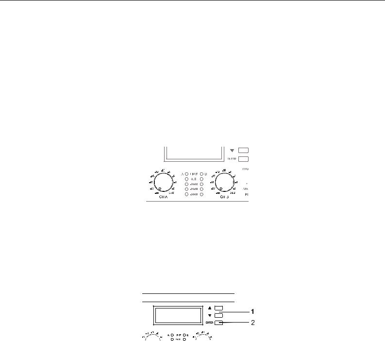
2.1 Controls, Indicators and Connections
Front View
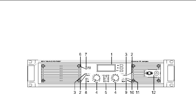
Illustration 2.1: H2500/H5000 front view
1LC-Display (with controls)
2Muting Indicator (MUTE) for channels A and B
3Protections Indicator (PROTECT) for channels A and B
4Input Level Control (CH A, CH B) for channels A and B
5Level Indicators for channels A and B
6Audio Input Mode Indicator (PARALLEL)
7Power Amplifier Mode Indicator (BRIDGED)
8Input Sensitivity/Gain Indicator (0dBu, 35dB, 32dB)
9Remote Amplifier Indicator (IRIS-Net)
10Standby Indicator (STANDBY)
11Power On/Off Indicator (POWER)
12Mains Switch
Owner’s Manual 7
PowerH SERIES
Rear View
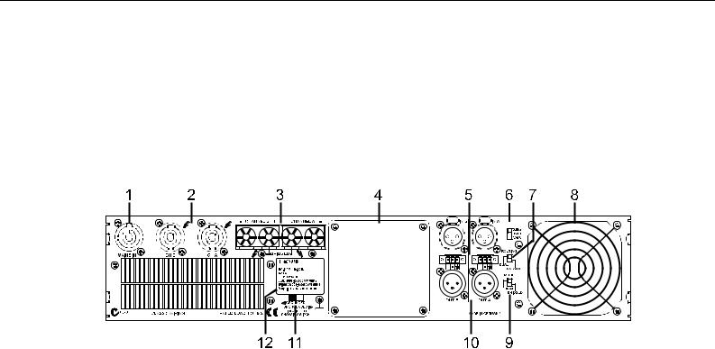
Illustration 2.2: H2500/H5000 rear view
1PowerCon® Mains Input (MAINS IN)
2Speakon™ Female-Type Power Amp Outputs (CH A, CH B)
3Power Amp Output Terminals (CHANNEL A, CHANNEL B, BRIDGED)
4Expansion Slot
5XLR and Phoenix-Type Audio Inputs (IN A, IN B)
6Input Sensitivity/Gain Switch
7Audio Inputs Routing Switch (ROUTING)
8Fan
9Power Amp Outputs Mode Switch (MODE)
10XLR-Type Audio Outputs (OUT A, OUT B)
11Ground Lift Switch (CIRCUIT TO CHASSIS SWITCH)
12Type Plate
8 Owner’s Manual

PowerH SERIES
Factory Settings
|
Control |
|
Setting |
|
|
|
|
|
|
|
|
|
Mains Switch |
|
off |
|
|
|
|
|
|
|
|
|
Level CH A |
|
0dB |
|
|
|
|
|
|
|
|
|
Level CH B |
|
0dB |
|
|
|
|
|
|
|
|
|
Table 2.1: Factory Settings of the Controls |
||||
|
|
|
|
|
|
Parameter |
|
|
|
Value |
|
|
|
|
|
|
|
Power-On-Delay |
0.00 s |
||||
|
|
|
|
||
Breaker Current (dependent on the mains) |
16 A (230 V) / 30 A (120 V) |
||||
|
|
|
|
||
Amplifier Name |
Dynacord H2500 or Dynacord H5000 |
||||
|
|
|
|
|
|
LCD Contrast |
50% |
|
|
||
|
|
|
|
|
|
LCD Brightness High |
90% |
|
|
||
|
|
|
|
|
|
LCD Brightness Low |
40% |
|
|
||
|
|
|
|
||
LCD Time to Dim |
Autodim off |
||||
|
|
|
|
||
Temperature Unit |
°C |
||||
|
|
|
|
||
Table 2.2: Factory Settings of the LC-Display |
|||||
|
|
|
|
|
|
|
Controls |
|
Setting |
|
|
|
|
|
|
|
|
|
ROUTING |
DUAL |
|
|
|
|
|
|
|
||
|
MODE |
NORMAL |
|
|
|
|
|
|
|
||
|
SENSITIVITY/GAIN |
0dBu |
|
|
|
|
|
|
|
||
|
GROUNDLIFT |
GROUNDED |
|
|
|
|
|
|
|
|
|
Table 2.3: Factory Settings of the Rear Panel Controls
2.2 Operating Voltage
The power amplifier receives its power supply via the MAINS IN connector, which is designed as a Neutrik PowerCon® connector.
CAUTION:
The Powercon® is a connector without breaking capacity, i.e. the Powercon® should not be connected or disconnected under load or live.
Owner’s Manual 9
PowerH SERIES
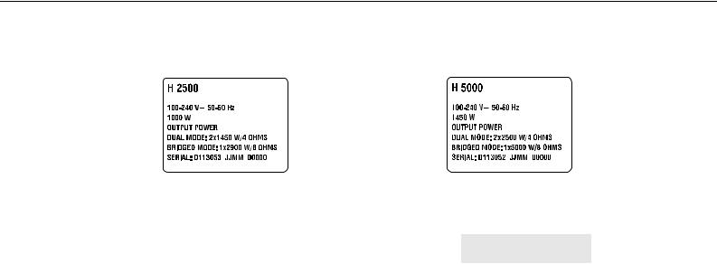
During installation, always separate the power amplifier from the mains. Connect the power amplifier only to a mains network, which corresponds to the requirements indicated on the type plate.
Illustration 2.3: H2500/H5000 type plate
Device |
Voltage |
Frequency |
Power Consumption |
|
|
|
|
H2500 |
100-240 V |
50-60 Hz |
1000 W |
|
|
|
|
H5000 |
100-240 V |
50-60 Hz |
1450 W |
|
|
|
|
|
Table 2.4: Specifications for the Power Supply Unit |
||
Mains Operation & Resulting Temperature
The following tables allow the determination of power supply and cabling requirements. The power drawn from the mains network is converted into output power to feed the connected loudspeaker systems and into heat. The difference between power consumption and dispensed power is called power dissipation (Pd). The amount of heat resulting from power dissipation might remain inside of a rack-shelf and needs to
be diverted using appropriate measures. The following table is meant as auxiliary means for calculating temperatures inside of a rack-shelf system/cabinet and the ventilation efforts necessary.
The column Pd lists the leakage power in relation to different operational states. The column BTU/hr lists the dispensed heat amount per hour.
H2500 |
Umains in V |
Imains in A |
Pmains in W |
Pout in W |
Pd in W1 |
BTU/hr2 |
Idle |
230 |
0.7 |
70 |
- |
70 |
239 |
Max. Output Power @ 8 Ω3 |
230 |
15.3 |
2420 |
2 x 850 |
720 |
2457 |
Max. Output Power @ 4 Ω3 |
230 |
25.7 |
4300 |
2 x 1450 |
1400 |
4777 |
1/3 Max. Output Power @ 4 Ω3 |
230 |
14.7 |
2325 |
2 x 483 |
1358 |
4635 |
1/8 Max. Output Power @ 4 Ω3 |
230 |
6.2 |
875 |
2 x 181 |
513 |
1749 |
1/8 Max. Output Power @ 4 Ω4 |
230 |
6.7 |
1000 |
2 x 181 |
588 |
2005 |
1/8 Max. Output Power @ 4 Ω4 5 |
253 |
7.1 |
1105 |
2 x 219 |
666 |
2274 |
Normal Mode (-10 dB) @ 4 Ω3 |
230 |
5.6 |
775 |
2 x 145 |
485 |
1655 |
Rated Output Power (0 dB) @ 4 Ω3 |
230 |
23.5 |
3900 |
2 x 1200 |
1500 |
5118 |
Alert (Alarm) Mode (-3 dB) @ 4 Ω3 |
230 |
16.7 |
2665 |
2 x 600 |
1465 |
4999 |
Max. Output Power @ 2 Ω3 |
230 |
39.6 |
6920 |
2 x 2000 |
2920 |
9963 |
1/8 Max. Output Power @ 2 Ω3 |
230 |
9.1 |
1345 |
2 x 238 |
870 |
2969 |
1/8 Max. Output Power @ 2 Ω4 |
230 |
9.1 |
1335 |
2 x 238 |
860 |
2934 |
10 Owner’s Manual
PowerH SERIES
H5000 |
Umains in V |
Imains in A |
Pmains in W |
Pout in W |
Pd in W1 |
BTU/hr2 |
Idle |
230 |
0.7 |
78 |
- |
78 |
266 |
Max. Output Power @ 8 Ω3 |
230 |
24.5 |
4089 |
2 x 1500 |
1089 |
3716 |
Max. Output Power @ 4 Ω3 |
230 |
40.9 |
7137 |
2 x 2500 |
2137 |
7292 |
1/3 Max. Output Power @ 4 Ω3 |
230 |
18.1 |
2927 |
2 x 833 |
1260 |
4300 |
1/8 Max. Output Power @ 4 Ω3 |
230 |
6.2 |
877 |
2 x 313 |
252 |
860 |
1/8 Max. Output Power @ 4 Ω4 |
230 |
9.6 |
1450 |
2 x 313 |
806 |
2750 |
1/8 Max. Output Power @ 4 Ω4 5 |
253 |
11.6 |
1944 |
2 x 378 |
1188 |
4053 |
Normal Mode (-10 dB) @ 4 Ω3 |
230 |
9.2 |
1368 |
2 x 250 |
868 |
2962 |
Rated Output Power (0 dB) @ 4 Ω3 |
230 |
37.5 |
6445 |
2 x 2100 |
2245 |
7660 |
Alert (Alarm) Mode (-3 dB) @ 4 Ω3 |
230 |
22.7 |
3760 |
2 x 1050 |
1660 |
5664 |
Max. Output Power @ 2 Ω3 |
230 |
44.3 |
8180 |
2 x 3500 |
1180 |
4026 |
1/8 Max. Output Power @ 2 Ω3 |
230 |
15.3 |
2427 |
2 x 438 |
1552 |
5296 |
1/8 Max. Output Power @ 2 Ω4 |
230 |
13.6 |
2105 |
2 x 438 |
1230 |
4197 |
1.Pd = Power Dissipation |
|
|
|
|
|
|
2.1 BTU = 1055.06 J = 1055.06 Ws |
|
|
|
|
|
|
3.Sine Modulation (1 kHz) |
|
|
|
|
|
|
4.Pink-Noise EN60065 / 7. Edition 5.10% Mains Over Voltage
The following factors allow direct proportional calculation of the mains current Imains for different mains supply voltages: 100 V = 2.3, 120 V = 1.9, 220 V = 1.05, 240 V = 0.97.
2.3 Mains Switch
The Mains Switch on the front panel separates the power amp from the mains. Pressing the Mains Switch starts booting up the power amp. A soft start circuit compensates mains inrush current peaks and thus prevents the automatic cutout of the mains from reacting when switching on the power amplifier. Speaker system switch-on is delayed by approximately 2 seconds via output relays, effectively suppressing any possible power-on noise, which otherwise might be heard through the loudspeakers. MUTE-LED light and the fans are running during this delay.
Owner’s Manual 11
PowerH SERIES
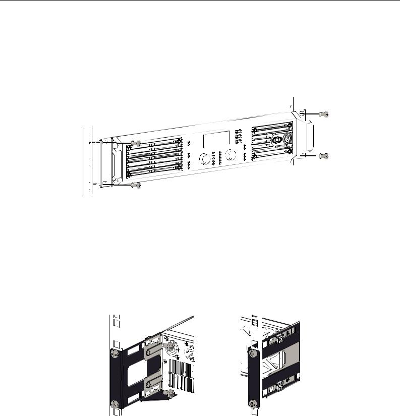
2.4 Mounting
Front Mounting of the Power Amplifier
PowerH amplifiers have been designed for installation in a conventional 19-inch rack case. Attach the power amp with its frontal rack mount ears using 4 screws and washers as shown in illustration 2.4.
Illustration 2.4: Front mounting when installing the power amplifier in a rack case
Rear Mounting
Additionally securing the amplifier at the rear becomes necessary, if the rack case in which the power amplifier has been installed will be transported. Failure to do so may result in damage to the power amplifier as well as to the rack case. Brackets for securing the power amplifier are supplied. Attach the power amp as shown in illustration 2.5 using the supplied 4 case nuts and screws.
Illustration 2.5: Rear mounting when installing the power amplifier in a rack case
12 Owner’s Manual
PowerH SERIES
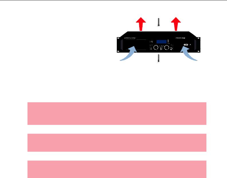
2.5 Ventilation
As with all Dynacord power amps with fan
cooling, the airflow direction is front-to-rear, obviously because there is more cold air
outside of the rack case than inside. The power
amplifier remains cooler and dissipating the developing waste heat in a specific direction gets easier. In general, setting up or mounting
the power amplifier has to be done in a way that fresh air can enter unhindered at the front and
exhausted air can exit at the rear. When installing the power amp in a case or rack
system, attention should be paid to these details
to provide sufficient ventilation. Allow for an air duct of at least 60 mm x 330 mm between the rear panel of the power amplifier and the inner wall of the cabinet/rack case. Make sure that the duct reaches up to the cabinet’s or the rack case’s top ventilation louvers. Leave room of at least 100 mm above the cabinet/rack case for ventilation. Since temperatures inside of the cabinet/rack case can easily rise up to 40 °C during operation of the power amp, it is mandatory to bear in mind the maximum allowable ambient temperature for all other appliances installed in the same cabinet/rack case.
CAUTION:
Blocking/closing the power amp’s ventilation louvers is not permissible. Without sufficient cooling/ventilation, the power amplifier may automatically enter protect mode. Keep ventilation louvers free from dust to ensure unhindered airflow.
CAUTION:
Do not use the power amplifier near heat sources, like heater blowers, stoves or any other heat radiating devices.
CAUTION:
To ensure trouble-free operation, make certain that the maximum allowable ambient temperature of +40 °C is not exceeded.
For fixed amplifier installations in a device control room that incorporate a central air-cooling system or air conditioners, calculating the maximum heat emission may be necessary. Please also take notice of the information on page 10.
2.6 Groundlift
The ground lift switch allows eliminating noise loops. When operating the power amplifier together with other equipment in a rack case, setting the switch to the GROUNDED position is recommended. Set the switch to UNGROUNDED, when the power amplifier is operated together with appliances with differing ground potentials.
Owner’s Manual 13

PowerH SERIES
2.7 Indication of the Operation Mode
Two LEDs on the power amp’s front panel indicate the currently selected mode of operation. The PARALLEL-LED lights yellow, when the ROUTING switch is set to PARALLEL. The PARALLEL LED does not light, when the switch is set to DUAL. The BRIDGED LED lights yellow, when the MODE switch is set to BRIDGED. The BRIDGED LED does not light, when the switch is set to NORMAL.
2.8 Selecting the Mode Of Operation
ROUTING
The ROUTING switch on the power amp’s rear panel defines how the audio inputs handle the input signals.
DUAL
In DUAL mode, the two channels of the power amplifier work independent from each other. This mode of operation is being used for all 2-channel applications, like stereo or Bi-Amp (active) operation. Using the input level controls on the power amp’s front panel or an optionally available remote control module and IRIS-Net™ allows independently adjusting the channels’ amplification.
Illustration 2.7: Audio signal applied to both input connectors in DUAL mode
PARALLEL
In PARALLEL mode, the inputs of channel A and channel B are directly electrically linked. The audio signal has to be applied to the input connectors (XLR or Phoenix) of channel A. Using the input level controls or IRIS-Net™ to independently control the amplification of the two channels is still possible because only the channels’ inputs are linked. PARALLEL operation is the mode of choice, whenever the same input signal drives multiple power amp channels of a large system installation, e.g. when driving massive bass arrays.
Illustration 2.8: Audio signal applied to input connector A in PARALLEL mode
CAUTION:
In PARALLEL mode, the input signal has to be fed to input channel A only.
14 Owner’s Manual
PowerH SERIES
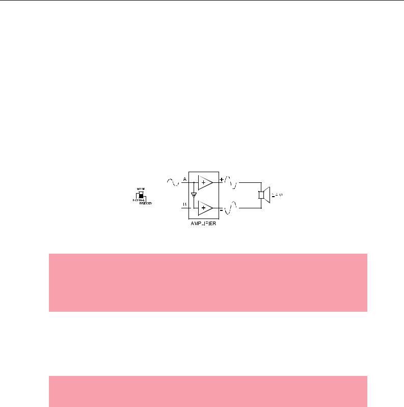
MODE
The MODE switch on the power amp’s rear panel defines the operation mode of the power amplifier blocks and thus, how a single or more speaker systems have to be connected.
NORMAL
In two-channel operation (NORMAL), both power amplifier blocks work as independent power amp channels and controlling the amplification of each channel separately is possible. How the power amp’s audio inputs handle input signals depends only on the setting of the ROUTING switch.
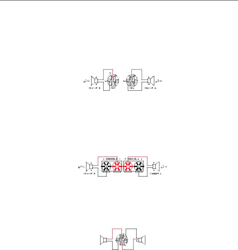
BRIDGED
In BRIDGED mode, the power amplifier functions as single-channel, monaural power amp. If the switch is set to DUAL (input channels work independent from each other), the audio signal has to be applied to either one of the input connectors (XLR or Phoenix) of channel A while channel B inputs are inactive. With the switch being set to PARALLEL, the audio signal may be fed to either one of the inputs of channel A or of channel B. In BRIDGED mode, the power amp channel A is modulated as usual.In addition, the input signal is internally inverted and applied to channel B. The A and B power amps act in push-pull operation delivering doubled output voltage.
Illustration 2.9: BRIDGED mode
CAUTION:
In BRIDGED mode operation, it is not allowable for the load connected to fall below a value of 4 ohms. Extremely high voltages can be present at the output. The connected speaker systems must be able to handle such voltages. Make sure to completely read and fully observe power rating specifications of the speaker systems to be used and to check them against the output power capacity of the power amp.
SENSITIVITY/GAIN
PowerH SERIES amplifiers can be operated at an input sensitivity of 0dBu as well as at a constant gain of 35dB or 32dB. A correspondingly labeled LED on the power amp’s front panel indicates the respective setting of the sensitivity/gain switch, which is located on the power amp’s rear panel.
NOTE:
If a remote control module is used the sensitivity/gain switch is deactivated and the sensitivity/gain of the amplfier is automatically set to 35 dB.
An Input sensitivity of 0dBu means that with an input signal of 0 dBu (0.775 Vrms), the signal at the power amplifier outputs is at Rated Output Power. This setting is recommended for audio signal sources that deliver a nominal output voltage of 0 dBu. As an alternative, operating the power amp at a constant gain of 35 dB or 32 dB is also possible. Operating all power amps in a setup – even those of different performance classes – at constant gain setting greatly simplifies the adjustment of signal processors. This allows the
Owner’s Manual 15
PowerH SERIES
installer to consider each power amplifier with a gain of 35 dB (or 32 dB) when setting gain structure, independent of the actual maximum output capacity of each individual power amp. Any limiters have to be adjusted to maximum power handling capacity of the loudspeaker components.
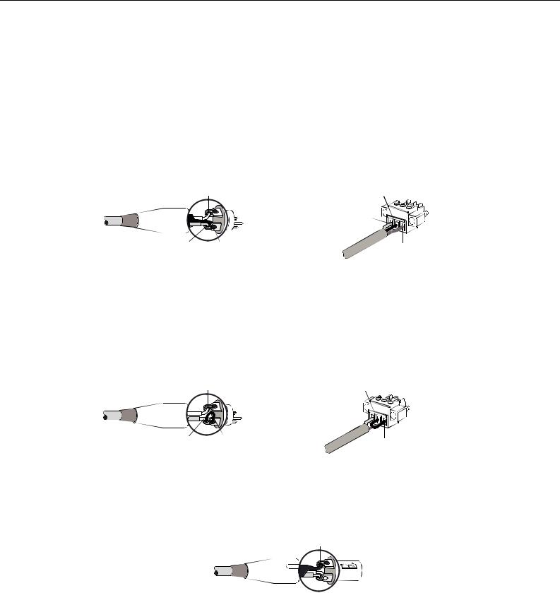
Audio Cabling
Input (XLR / Phoenix)
Inputs IN A and IN B are electronically balanced and the SENSITIVITY switch controls input sensitivity. Connection can be established either by using XLRor Phoenix-type connectors, which are connected in parallel. The needed Phoenix-type connectors are supplied with the power amplifier. The pin-assignment of XLRF-type connectors is in accordance with the IEC standard 268.
2, HOT |
COLD, - |
|
HOT, + |
3, COLD 1, SHIELD |
SHIELD |
Illustration 2.10: Balanced connection of input
Whenever possible, using balanced audio signal feeds at the input of the power amplifier is always preferred. Unbalanced connections should only be used if the cables are very short and no interfering signals are to be expected in the vicinity of the power amplifier. In this case, bridging the screen (shielding) and the pin of the inverting input inside of the connector is mandatory. Otherwise, a 6 dB drop in level could result. Please also see illustration 2.11. Due to their immunity against external interference sources, such as dimmers, mains connections, HF-control lines, etc., using balanced cabling and connections is always preferable.
2, HOT |
JUMPER FROM COLD TO SHIELD |
|
HOT, + |
3, COLD JUMPER |
SHIELD |
FROM COLD |
|
TO SHIELD |
|
Illustration 2.11: Unbalanced connection of input
Next to its input connector, each channel provides an individual XLR-type connector (OUT A or OUT B), which is connected in parallel to allow for comfortably daisy-chaining the audio signal for the connection of additional audio equipment.
1, SHIELD
3, COLD 2, HOT
Illustration 2.12: Balanced connection of output (Daisy-Chain)
16 Owner’s Manual
PowerH SERIES
Output (Speakon-type Connectors / Terminals) in Normal Mode
With PowerH SERIES amplifiers speaker connection differs depending on the actually selected mode of operation of the power amplifier blocks, i.e. the setting of the MODE switch on the power amp’s rear panel. In NORMAL mode, the loudspeaker systems can be connected in two different ways: using typical Speaker Systems Cabling or Bi-Amp Cabling.
Typical Speaker System Cabling
The first possibility is to use the two Speakon-type connectors, whereas speakers have to be connected to pins 1+ and 1– of the sockets, see illustration 2.13.
Illustration 2.13: Speaker connection in NORMAL operation mode, using Speakon A and B connectors
Speakon CH B |
|
Speakon CH A |
||
|
|
|
|
|
1+ |
1- |
Connector |
1+ |
1- |
|
|
|
|
|
B+ |
B- |
Assignment |
A+ |
A- |
|
|
|
|
|
Table 2.5: Speaker connection in NORMAL operation mode, using Speakon A and B connectors
Next to the Speakon-type sockets, conventional speaker terminals are provided as well. The following illustration shows how to connect the speaker systems for NORMAL mode operation.
Illustration 2.14: Speaker connection in NORMAL operation mode, using Terminals
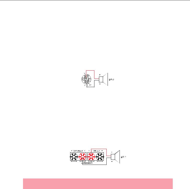
Bi-Amp Cabling
The second possibility for connecting the speakers when the power amplifier is operated in NORMAL mode is to only use the Speakon-type connector CH A and to connect one speaker cabinet to pins 1+ and 1–, as described above and the second cabinet to pins 2+ and 2– as shown in illustration 2.15. Only pins 2+ and 2– of the Speakon CH A connector are assigned. Proceeding like this facilitates the cabling of speaker systems that are used in active 2-way operation (Bi-Amp).
|
|
1+ |
|
|
+ |
|
|
|
+ |
≥ 2 Ω |
1- |
|
2- |
≥ 2 Ω |
- |
|
|
|
- |
CHANNEL A |
|
CH A |
2+ |
CHANNEL B |
Illustration 2.15: Bi-Amp speaker connection in NORMAL operation mode, using only the Speakon A connector
Owner’s Manual 17
PowerH SERIES
|
|
Speakon CH A |
|
|
|
|
|
|
|
Connection Pin |
1+ |
1- |
2+ |
2- |
|
|
|
|
|
Channel Assignment |
A+ |
A- |
B+ |
B- |
|
|
|
|
|
Table 2.6: Bi-Amp speaker connection in NORMAL operation mode, using only the Speakon A connector
Output (Speakon-type Connectors / Terminals) in Bridged Mode
Setting the MODE switch on the power amp’s rear panel to BRIDGED lets the power amplifier run in bridged mode operation and speaker connection has to be established using pins 1+ and 2+ of the Speakon socket CH A, see illustration 2.16.
Illustration 2.16: Speaker connection in BRIDGED operation mode, using Speakon A
|
Speakon CH A |
|
|
|
|
Connection Pin |
1+ |
2+ |
|
|
|
Channel Assignment |
Bridged+ |
Bridged- |
|
|
|
Table 2.7: Speaker connection in BRIDGED operation mode, using Speakon A
When using the speaker terminals in BRIDGED mode, the loudspeaker system has to be connected to the red terminals of CHANNEL A and CHANNEL B. An illustration of how to correctly establish speaker connection for this mode of operation is provided on the power amp’s enclosure.
Illustration 2.17: Speaker connection in BRIDGED operation mode, using Terminals
CAUTION:
Due to the high current, using banana plugs for speaker connection is not permissible.
18 Owner’s Manual
PowerH SERIES
3 Operation
3.1 Volume Control
In DUAL and PARALLEL mode, the level controls CH A and CH B on the power amp’s front panel are used to control the amplification of the corresponding channel. Turning the control to the right increases and turning it to the left decreases the volume. In BRIDGED mode operation, the output volume of the power amp is only controlled by the CH A level control. Any changes in the setting of the CH B level control are ignored.
With an installed remote control module, the level controls CH A and CH B may be deactivated, i.e. controlling the power amp’s amplification is only possible via IRIS-Net™. The Level Controls Off ! indicator on the LC display signals that the controls are deactivated.
Illustration 3.1: Level controls CH A and CH B
3.2 Graphical LC display
The graphical LC display provides detailed information about the operating status of the power amplifier. Furthermore, it is possible to change several settings of the power amp and, if installed, of a remote control module.
Illustration 3.2: LC display with controls
1Up  / Down
  buttons: These keys allow navigating through the menu.
2ENTER button: Pressing this key selects the highlighted menu entry.
Owner’s Manual 19

PowerH SERIES
Power Amplifier Menu Navigation
Start screen and type designation appear after switching the power amplifier on. The power amp’s status display appears after a few seconds. The top line always shows the name of the power amplifier. An overview of the power amp’s actual condition is provided in lines two and three. Flashing values in line 2 indicate reaching the limit of the permissible operating range. Additional information is shown if, for example, a RCM-26 has been installed in the power amplifier.
Illustration 3.3: Status display of the power amplifier without / with RCM-26 installed (example)
Using the Up/Down buttons lets you scroll through the bottom line. The following table lists the information, which is displayed in consecutive order.
Set CAN address and CAN baud rate (only with RCM-26 installed)
Name of the actual preset (only with RCM-26 installed)
Currently used audio input of the power amp (only with
RCM-26 installed)
Status of the input level controls on the power amp’s front panel (only with RCM-26 installed)
Currently active parameters for the mode of operation, sensitivity and Mains Circuit Breaker Protection (only with RCM-26 installed)
Power-on delay of the power amp
Actual parameter for the Mains Circuit Breaker Protection
Pressing the ENTER button branches to the CONFIG configuration menu.
Table 3.1: Overview status display
20 Owner’s Manual
PowerH SERIES
The following illustration shows the structure of the CONFIG menu (and its associated submenus) when opening it from the status display. Menu entries marked with an asterisk * are only available when the remote control module is not installed.
Status display
EVENT LOG |
Counter POWER UP |
Counter AMP ON |
Counter PROTECT |
Counter AMP MUTE |
Counter MAINS FAIL |
Uptime |
Show Event History |
Reset Event Log |
BACK |
Power-On-Delay
Breaker Current
Show Event Log
Menu Display
Menu Service
Amplifier Name*
EXIT
DISPLAY SETUP |
LCD Contrast |
LCD Brightness |
LCD Time to Dim |
Temperature Unit |
BACK |
SERVICE |
Restore Amplifier’s |
Factory Settings |
Lifetime |
Last Log |
Module Signature |
Firmware Version |
BACK |
Illustration 3.4: The power amp’s menu structure
Owner’s Manual 21

PowerH SERIES
Structure of the CONFIG menu
Entering the CONFIG menu is possible through pressing the ENTER button while the entry >> CONFIG << is highlighted in the status display. The following provides detailed information about the individual items of the configuration menu.
CONFIG/Power-On-Delay: The power amp’s currently set poweron delay is shown. Pressing the ENTER-Taste button opens the
Set Power-On-Delay dialog box.
Using the Up/Down buttons in the Set Power-On-Delay lets the user specify a delay in the range of 0 seconds to up to 6.35 seconds. Pressing the ENTER button again stores the previously made setting and the display returns to the CONFIG menu.
CONFIG/Breaker Current: The actually set value of the current that controls the Mains Circuit Breaker Protection is displayed. The set current has to match the value of the power amp’s internal fuse for the protection to work correctly. Please refer to the explanations on page 32 for more details. Pressing the ENTER button opens the Set Breaker Current dialog box where the desired value for the breaker current can be set.
The valid value ranges depend on the power amp’s power supply. Currents between 6 A and 40 A can be set when the power amplifier is operated at 120 V. Currents between 6 A and 30 A can be set when the power amplifier is operated at 220-240 V. Select Factory 30 A or Factory 16 A for automatic setting depending on the power amp’s power supply. Pressing the ENTER button stores the selected current value in memory and the CONFIG menu reappears on the display.
NOTE:
Operating the power amplifier on a separately fused mains power line is recommended only.
CONFIG/Show Event Log: The menu entry Show Event Log leads to the EVENT LOG submenu. The individual entries in the EVENT LOG menu are explained in detail in the paragraph
Structure of the CONFIG.EVENT LOG menu (see page 23).
CONFIG/Menu Display: The menu entry Menu Display leads to the DISPLAY SETUP submenu. Each entry in the DISPLAY SETUP menu is explained in detail in paragraph
Structure of the CONFIG/DISPLAY SETUP menu (see page 24).
22 Owner’s Manual
PowerH SERIES
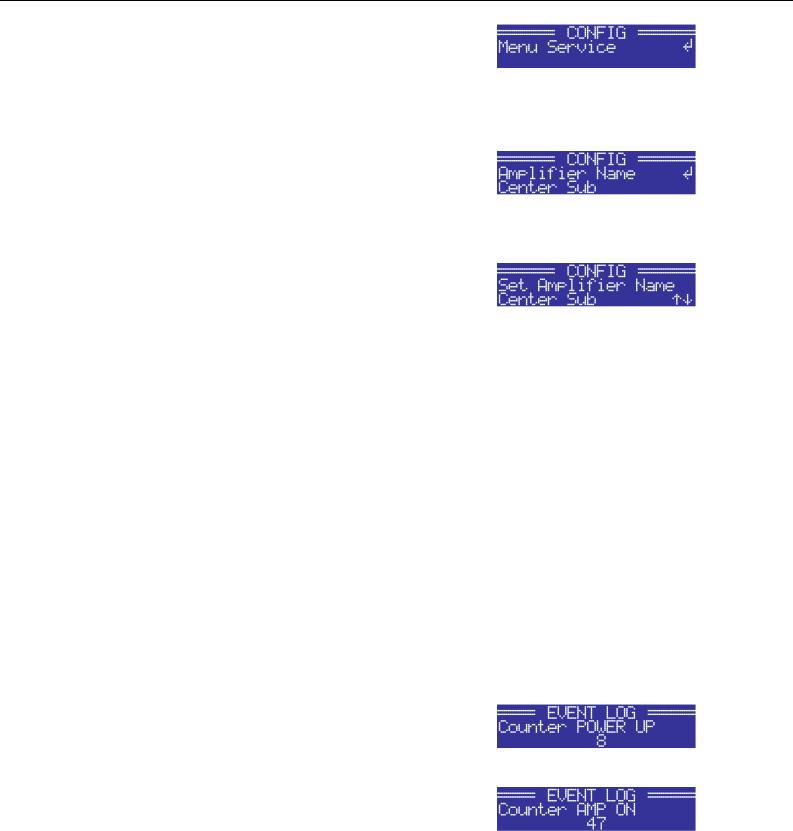
CONFIG/Menu Service: The menu entry Menu Service branches to the SERVICE submenu. The entries in the SERVICE menu are explained in detail in paragraph Structure of the CONFIG/SERVICE menu (see page 26).
CONFIG/Amplifier Name: Displays the name of the power amplifier. The menu entry only exists when no RCM-26 is installed in the power amplifier. With a remote control module installed, the power amplifier has to be named via IRIS-Net™. Pressing the ENTER button opens the Set Amplifier Name dialog box.
The Set Amplifier Name dialog allows changing the power amp’s name, which can be composed of a maximum of 20 symbols and consist of all letters a-z, A-Z, the numbers 0-9 and special characters.
Pressing the Up/Down buttons locates the cursor at the desired position of the name. Pressing the ENTER button accepts the desired symbol and moves the cursor to the next character. Pressing the ENTER button after manipulating the last character, stores the desired name of the power amplifier in the memory and the display returns to the CONFIG menu.
The following special characters provide special functions when entering a power amp’s name:
Character |
Function |
|
|
|
Accepts the entered name and returns to the menu. |
|
|
A |
Deletes the currently selected symbol and moves the cursor by one character to the right. |
|
|
I |
Set the cursor by one character to the left. |
|
|
Table 3.2: Functions of special characters when entering the power amp’s name
Structure of the CONFIG/EVENT LOG menu
CONFIG/EVENT LOG/Counter POWER UP: This menu item shows how many times the power switch on the front panel has been used.
CONFIG/EVENT LOG/Counter AMP ON: This menu item shows how often the power amplifier has been activated from the OFF or STANDBY state.
Owner’s Manual 23
PowerH SERIES
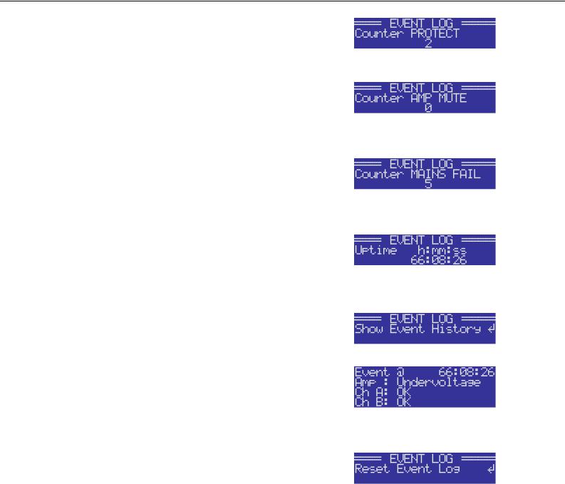
CONFIG/EVENT LOG/Counter PROTECT: This item shows how many times one of the protections has been activated.
CONFIG/EVENT LOG/Counter AMP MUTE: This menu item shows how often the power amp’s output signal has been muted by one of the protections.
CONFIG/EVENT LOG/Counter MAINS FAIL: This menu item shows how many times overor undervoltage has been recognized at the power amp’s power supply unit.
CONFIG/EVENT LOG/Uptime: This menu item shows the total running time of the power amplifier (not counting standby times) since the last reset of the Event Log.
CONFIG/EVENT LOG/Show Event History: The Show Event History menu entry opens a list of all events in chronological order (last event shown first) that have been registered. Pressing the ENTER button selects the desired item in the list.
Point in time and cause of the occurrence is shown for each item in the list. The state of operation of the amplifier (Amp) and the two output channels (Ch A or Ch B) is indicated for each event. Pressing the Up/Down buttons lets the user scroll through the list of entries. Pressing the ENTER button lets one return to the CONFIG. menu.
CONFIG/EVENT LOG/Reset Event Log: The user can completely reset the Event Log of the power amplifier in this menu entry. All counters are reset to zero and the event log is deleted. Pressing the ENTER button opens a safety dialog box that lets the user choose between YES or NO by pressing the Up/Down buttons. If YES has been selected, pressing the ENTER button resets the Event Log. If the user decides to select NO, the Event Log stays unchanged and the CONFIG. menu reappears on the display.
24 Owner’s Manual

PowerH SERIES
Structure of the CONFIG/DISPLAY SETUP menu
CONFIG/DISPLAY SETUP/LCD Contrast: This menu item indicates the currently set contrast of the LC display. Pressing the ENTER button opens the Set LCD Contrast where the user can select a contrast setting in the range of 0 % to 100 % by using the Up/Down buttons. Pressing the ENTER button again stores the selected value for contrast in memory and the CONFIG menu reappears on the display.
CONFIG/DISPLAY SETUP/LCD Brightness: The currently set maximum and minimum values for display brightness are indicated. The maximum value represents the brightness of the display that is used during normal operation. The minimum value represents the brightness of the display that it is adjusted to after a specific period of time, if desired.
Pressing the ENTER button opens the Set Brightn. Hi-Lvl dialog box, which, by pressing the Up/Down buttons, allows setting the undimmed display brightness in a range of 50 % to 100 %.
Pressing the ENTER button stores the set brightness value in memory and the display indication changes to the Set Brightn. Lo-Lvl dialog box, where pressing the Up/ Down buttons allows setting the dimmed display brightness in a range of 0 % to 80 %. Pressing the ENTER button again stores the set brightness value and the display returns to the CONFIG. menu.
CONFIG/DISPLAY SETUP/LCD Time to Dim: The currently set time interval, during which the display lights with the maximum brightness it has been set to, is indicated. After the time interval has expired the display is dimmed.
Pressing the ENTER button opens the Set LCD Time to Dim dialog box, where the user can specify the duration after which the display dimming starts by pressing the Up/Down buttons. The duration can be set to 4, 8, 16, 32 or 64 minutes. Alternately, the user can select Autodim off to completely deactivate the dimming function, which results in the display always lighting at the set maximum brightness level (Brightn. Hi-Lvl).
For an increased lifetime of the display, activating the dimming function is recommended. Pressing the ENTER button stores the settings in memory and the display returns to the CONFIG menu.
Owner’s Manual 25

PowerH SERIES
CONFIG/DISPLAY SETUP/Temperature Unit: The currently selected unit for the indication of temperature values is displayed.
Pressing the ENTER button opens the Set Temperature Unit dialog box, which allows selecting °C (Degrees Celsius) or °F (Degrees Fahrenheit) by pressing the Up/Down buttons. Pressing the ENTER button stores the selected unit in memory and the CONFIG menu reappears on the display.
Structure of the CONFIG/SERVICE menu
CONFIG/SERVICE/Restore Amplifier’s Factory Settings: The power amplifier can be reset to factory settings. Pressing the ENTER button opens a safety dialog box that lets the user choose between YES or NO by pressing the Up/Down buttons. If YES has been selected, pressing the ENTER button resets the power amplifier to its factory settings. If the user selected NO, all power amp parameters stay unchanged and the display returns to the CONFIG. menu.
The following table lists all parameters that are affected by a reset:
Parameter |
Value |
|
|
Power-On-Delay |
0.00 s |
|
|
Breaker Current (depends on |
16 A (230 V) / 30 A (120 V) |
the supply voltage) |
|
|
|
Amplifier Name |
Dynacord H2500 |
|
or |
|
Dynacord H5000 |
|
|
LCD Contrast |
50 % |
|
|
LCD Brightness High |
90 % |
|
|
LCD Brightness Low |
40 % |
|
|
LCD Time to Dim |
Autodim off |
|
|
Temperature Unit |
°C |
|
|
Table 3.3: Factory settings of the LC display
CONFIG/SERVICE/Lifetime: This menu item shows the total running time of the power amplifier (not counting standby times).
26 Owner’s Manual
PowerH SERIES
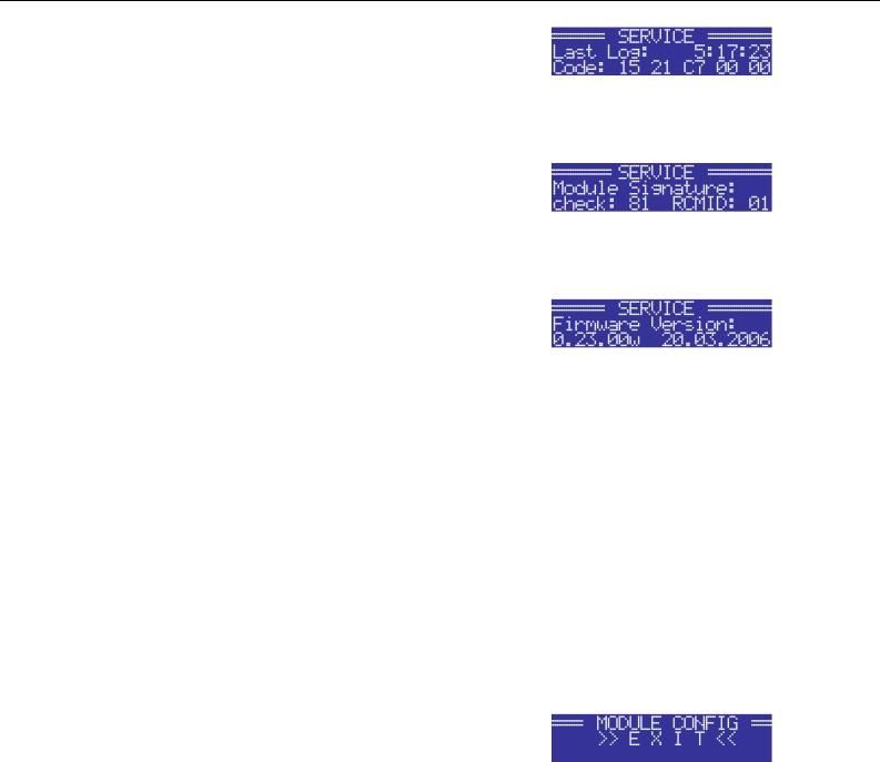
CONFIG/SERVICE/Last Log: Shows point in time and type of the last entry in the event history. If service is needed, the code shown here provides relevant detail of what might have caused the malfunction for your Dynacord Service partner.
CONFIG/SERVICE/Module Signature: In the event of failure or malfunction, the information shown here provides relevant detail of what might have caused the malfunction for your Dynacord Service partner.
CONFIG/SERVICE/Firmware Version: This menu item shows version and date of the firmware that is actually installed in the power amplifier.
Structure of the MODULE CONFIG menu
The MODULE CONFIG menu provides access to RCM-26 remote control module settings, which are available from the LC display of the power amplifier. This menu cannot be accessed during operation of the power amplifier. Accessing this menu is only possible when the power amp is switched off.
The following steps open the MODULE CONFIG menu:
1.If the power amplifier is powered on or in standby mode, use the mains switch on the front panel to switch the power amp off.
2.Simultaneously press the  and ENTER buttons and keep them pressed.
3.Use the power switch on the front panel to switch the power amplifier on.
The power amp enters standby mode and the MODULE CONFIG menu appears on the display.
Owner’s Manual 27
PowerH SERIES
Illustration 3.5 shows the structure of the MODULE CONFIG menu of a PowerH SERIES amplifier with an installed RCM-26 remote control module.
EXIT
Preset
CAN-Baudrate
Audio-Input
Power
Illustration 3.5: Structure of the Module Config menu (RCM-26)
The following provides detailed information about the individual items of the MODULE CONFIG menu.
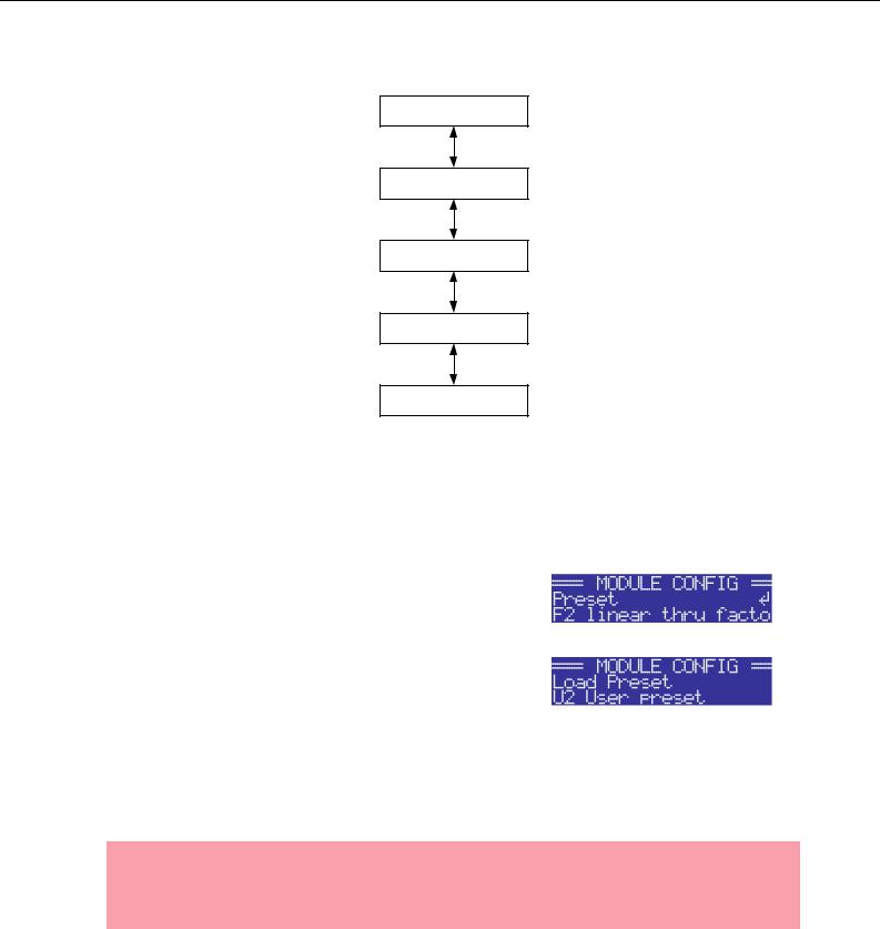
MODULE CONFIG/Preset: The name of the currently active preset is displayed. Pressing the ENTER button opens the Load Preset dialog box, which allows the user to select a preset by pressing the Up/Down buttons.
Pressing the ENTER button opens a safety dialog box, which lets the user select whether he actually wants to load the selected preset by pressing the Up/Down buttons to either select YES or NO. When YES has been selected, pressing the ENTER button loads the selected preset and the display returns to the MODULE CONFIG menu. When NO has been selected, the selected preset is not loaded. The power amp’s currently active preset is not changed and the MODULE CONFIG menu reappears on the display.
CAUTION:
The selected preset must be suitable for the use with the connected loudspeaker components. A incorrectly adjusted preset or incompatible preset can cause serious damage to the connected speaker systems.
28 Owner’s Manual
PowerH SERIES
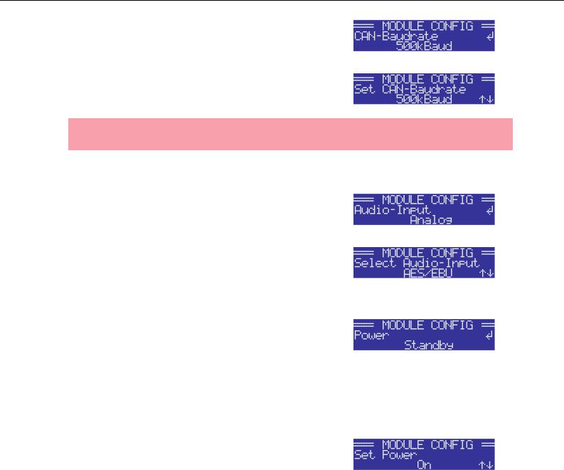
MODULE CONFIG/CAN-Baudrate: The currently set CAN baud rate of the RCM-26 is being indicated. Pressing the ENTER button opens the Set CAN-Baudrate dialog box, which by pressing the Up/Down buttons, lets the user select one of the following CAN baud rates: 10kBaud, 20kBaud, 62.5kBaud, 125kBaud, 250kBaud or 500kBaud.
Pressing the ENTER button stores the selected baud rate in memory and the display returns to the MODULE CONFIG menu.
CAUTION:
All devices on a specific CAN-BUS must be set to the same baud rate.
MODULE CONFIG/Audio-Input: The currently used audio input is indicated. Pressing the ENTER button opens the Select Audio-Input dialog box, which, by pressing the Up/ Down buttons, allows selecting Analog or AES/EBU inputs. Pressing the ENTER button stores the desired input in memory and the display returns to the MODULE CONFIG menu.
MODULE CONFIG/Power: The power amp’s actual operating status after using the mains switch is displayed.
If standby mode has been activated via IRIS-Net™ and the power amplifier has been switched off using the mains switch, the power amp automatically restarts into standby mode the next time it is switched on by pressing the mains switch. This menu item allows booting the power amplifier out of standby mode, even without IRIS-Net™.
Pressing the ENTER button opens the Set Power dialog box, which allows the selection of On or Standby operating states by pressing the Up/Down buttons. Pressing the ENTER button stores the desired status in memory and the MODULE CONFIG menu reappears on the display.
Owner’s Manual 29

PowerH SERIES
3.3 Indications
PROTECT
Whenever the PROTECT-LED lights yellow, one of the internal protections has been activated. However, a lit PROTECT-LED does not necessarily mean that the signal path gets switched off. The differentiated protections concept of PowerH SERIES power amps results in several protection circuits being activated one after another, which ensures that under normal circumstances the power amplifier will stay in the safe and stabile operating range. In case the amplifier needs to be switched off to prevent power amplifier and connected speaker systems from being damaged, this is indicated by the PROTECT and MUTE-LEDs being lit simultaneously.
MUTE
The MUTE-LED lights red whenever the power amp’s output signal is being muted, which happens for example during power-on delay of the speaker systems, when switching the input sensitivity, and when manually muting the output signal via IRIS-Net™.
-30dB…LIMIT
Level indication is realized via two vertical LED chains on the power amp’s front panel that individually indicate the actual levels of each channel at -30dB, -20dB, -10dB below full modulation and 0dB as soon as full modulation is reached. 0 dB indication results from comparing the power amp’s internal ratio of input to output voltage, which ensures precise indication of the full modulation limit, even before limiting becomes audible. If the input audio signal is driven above the 0 dB mark, a clipping limiter reliably controls distortion down to a stable rate of 1 %. The red LIMIT-LED has a dynamic brightness control that makes it easy to perceive the degree of limiting applied to the signal.
POWER
The POWER-LED lights green when the power amplifier is on. If the POWER-LED does not light, despite the fact that the amplifier has been switched on, this indicates that the power amp is not connected to the mains, the primary fuse has blown, or the amplifier is in standby mode (the STANDBY-LED lights yellow). The POWER-LED blinks whenever the voltage at the MAINS IN is too high (overvoltage) or too low (undervoltage), which prevents that the power amplifier can be switched on.
STANDBY
The STANDBY-LED lights yellow when the power amp is in standby mode. Standby mode reduces the amp’s power consumption to an absolute minimum. Activating the standby mode is only possible via IRISNet™. Deactivating the standby mode is possible via IRIS-Net™ as well as directly on the power amplifier. For deactivating the standby mode, select Power from the Module Setup menu (see page 29).
30 Owner’s Manual
Loading...