


2200
OWNER‘S MANUAL
BEDIENUNGSANLEITUNG
MODE D‘EMPLOI
CMS 1000/1600/2200
COMPACT MIXING SYSTEM

CONTENTS
SAFETY- AND SERVICE INSTRUCTIONS ....................... 3
IMPORTANT SAFETY INSTRUCTIONS ....................... 3
IMPORTANT SERVICE INSTRUCTIONS ....................... 3
DESCRIPTIONS ....................... 4
UNPACKING AND WARRANTY ....................... 4
INSTALLATION AND CONNECTIONS ....................... 4
INPUT MONO ....................... 5
INPUT STEREO ....................... 10
EFFECT 1/2 ....................... 13
AUX3&4 ....................... 15
MASTER ....................... 16
REAR PANEL ....................... 20
CABLING ....................... 21
SETTING UP A STANDARD-PA SYSTEM ....................... 22
SETUP EXAMPLES ....................... 24
SPECIFICATIONS ....................... 75
BLOCK DIAGRAM ....................... 76
DIMENSIONS ....................... 77
INHALTSVERZEICHNIS
SICHERHEITS- UND SERVICEHINWEISE ....................... 27
WICHTIGE SICHERHEITSHINWEISE ....................... 27
WICHTIGE SERVICEHINWEISE ....................... 27
BESCHREIBUNG ....................... 28
AUSPACKEN UND GARANTIE ....................... 28
AUFSTELLEN UND ANSCHLIEßEN ....................... 28
INPUT MONO ....................... 29
INPUT STEREO ....................... 34
EFFEKT 1/2 ....................... 37
AUX3&4 ....................... 39
MASTER ....................... 41
RÜCKSEITE ....................... 44
VERKABELUNG ....................... 45
AUFBAU EINER STANDARD-PA ....................... 46
AUFBAUBEISPIELE ....................... 48
SPECIFICATIONS ....................... 75
BLOCK DIAGRAM ....................... 76
DIMENSIONS ....................... 77
TABLE DES MATIÈRES
INSTRUCTIONS DE SÉCURITÉ IMPORTANTES ................. 51
IMPORTANT SAFETY INSTRUCTIONS ....................... 51
IMPORTANT SERVICE INSTRUCTIONS ....................... 51
DESCRIPTIONS ....................... 52
DÉBALLAGE ET GARANTIE ....................... 52
INSTALLATION ET BRANCHEMENTS ....................... 52
ENTRÉE MONO ....................... 53
ENTRÉE STEREO ....................... 58
EFFET 1/2 ....................... 61
AUX3&4 ....................... 63
MASTER ....................... 64
P ANNEAU ARRIÈRE ....................... 68
CABLAGE ....................... 69
INSTALLATION D‘UN SYSTÈME DE SONORISATION ........ 70
EXEMPLES D‘INSTALLATION ....................... 72
SPECIFICATIONS ....................... 75
BLOCK DIAGRAM ....................... 76
DIMENSIONS ....................... 77
2

IMPORTANT SAFETY INSTRUCTIONS
The lightning fl ash with arrowhead symbol, within an
equilateral triangle is intended to alert the user to the
presence of uninsulated „dangerous voltage“ within the
product’s enclosure that may be of suffi cient magnitude
to constitute a risk of electric shock to persons.
The exclamation point within an equilateral triangle is
intended to alert the user to the presence of important
operating and maintance (servicing) instructions in the
1. Read these instructions.
2. Keep these instructions.
3. Heed all warnings.
4. Follow all instructions.
5. Do not use this apparatus near water.
6. Clean only with a dry cloth.
7. Do not block any ventilation openings. Install in accordance with the manufactures instructions.
8. Do not install near any heat sources such as radiators, heat registers, stoves, or other apparatus
(including amplifi ers) that produce heat.
9. Do not defeat the safety purpose of the polarized or grounding-type plug. A polarized plug has two blades
with one wider than the other. A grounding type plug has two blades and a third grounding prong. The wide
blade or the third prong are provided for your safety. If the provided plug does not fi t into your outlet, consult an
electrican for replacement of the obsolete outlet.
10. Protect the power cord from being walked on or pinched particularly at plugs, convenience receptacles,
and the point where they exit from the apparatus.
11. Only use attachments/accessories specifi ed by the manufacturer.
12. Unplug this apparatus during lightning storms or when unused for long periods of time.
13. Refer all servicing to qualifi ed service personnel. Servicing is required when the apparatus has been damaged
in any way, such as power-supply cord or plug is damaged, liquid has been spilled or objects have fallen into the
apparatus, the apparatus has been exposed to rain or moisture, does not operate normally, or has been dropped.
14. Do not expose this equipment to dripping or splashing and ensure that no objects fi lled with liquids, such as vases,
are placed on the equipment.
15. To completely disconnect this equipment from the AC Mains, disconnect the power supply cord plug from the AC
receptacle.
16. The mains plug of the power supply cord shall remain readily operable.
literature accompanying the appliance.
IMPORTANT SERVICE INSTRUCTIONS
CAUTION:
electric shock, do not perform any servicing other than that ontained in the Operating
Instructions unless you are qualifi ed to do so. Refer all servicing to qualifi ed service personnel.
1. Security regulations as stated in the EN 60065 (VDE 0860 / IEC 65) and the CSA E65 - 94 have to be obeyed when
servicing the appliance.
2. Use of a mains separator transformer is mandatory during maintenance while the appliance is opened, needs to be
operated and is connected to the mains.
3. Switch off the power before retrofi tting any extensions, changing the mains voltage or the output voltage.
4. The minimum distance between parts carrying mains voltage and any accessible metal piece (metal enclosure),
respectively between the mains poles has to be 3 mm and needs to be minded at all times. The minimum distance
between parts carrying mains voltage and any switches or breakers that are not connected to the mains (secondary
parts) has to be 6 mm and needs to be minded at all times.
5. Replacing special components that are marked in the circuit diagram using the security symbol (Note) is only
permissible when using original parts.
6. Altering the circuitry without prior consent or advice is not legitimate.
7. Any work security regulations that are applicable at the location where the appliance is being serviced have to be
strictly obeyed. This applies also to any regulations about the work place itself.
8. All instructions concerning the handling of MOS - circuits have to be observed.
These servicing instructions are for use by qualifi ed personnel only. To reduce the risk of
NOTE:
SAFETY COMPONENT ( MUST BE REPLACED BY ORIGINAL PART )
3

DESCRIPTIONS
In a world of plethora and mass production, quality , functionality and design are more important than ever. We at DYNACORD
design and manufacture fi rst-class products – “Made in Germany”– that provide positive experiences through real world-
optimized detail solutions. They are built to please you for a long time.
The highest degree of customer satisfaction is our supreme ambition.
Because of their comprehensive set of integrated features – like equalizer and effects units – the Compact Mixing Systems
CMS 1000/ CMS 1600 and CMS 2200 are professional mixers offering an optimized all-in-one solution for basically any application.
DYNACORD CMS consoles are quickly set up. Complicated rack confi guration and interference-prone wiring of several single
components cease to apply.
The extremely low noise and low distortion discrete microphone preamps built-into the CMS 1000 / CMS 1600 and CMS 2200 provide
excellent audio quality, setting new standards in the fi eld of professional mixer technology. Specially designed Gain Potentiometers
allow ergonomic fader control and additionally provide an extended control range of 60 dB.
Group-switch-able +48V phantom power, Vocal Voicing fi lters, 3-channel tone control section with semi-parametric midrange, 4 AUX
channels, PFL and MUTE, newly designed dust-proof ALPS-fader controls and the four almost identically laid out stereo channels
with additional microphone inputs are only a few details of the professionally equipped inputs section. Master and AUX 3+4 output
signals are electronically balanced and output via XLR-type connectors. Relay switching effi ciently suppresses switching noise.
Separate pre/post fader switching of the AUX 3+4 busses is provided within the master section. Two feedback fi lters in the monitor
busses, master standby switch, tape input and two 7-band graphic equalizers, which can optionally be used for the master or AUX
3+4 busses complete the professional feature set of the master section. Two parallel operating and individually controllable 24-bit
digital stereo effects units with 48-bit algorithms offer a total of 2 x 99 “live sound-optimized” presets in studio quality. Room and plate
hall, echo and chorus reverb, mono/stereo delay, modulated delay effects like chorus or fl anging as well as several special effects
are comfortably selectable via up/down keys. Storing the preferred start-up presets for both effects units is possible in program mode.
These presets are present instantly after powering on the mixer. The use of a global or two separate footswitches allows for global or
individual switching the effects on and off. A 12V/5W litlite mixer lamp can be connected at the lamp output, which is protected against
short-circuit and overload.
Stable enclosures with metal protective covers ensure trouble-free transport of the mixers without need for extra fl ight-cases.
Unpacking and Warranty
Open the packaging and take out the CMS. Remove the FX unit display’s protective foil. In addition to this owner’s manual you will
fi nd the mains supply cord and the warranty card. Please check, whether the warranty registration form is fi lled out correctly. Only
when this form is completed, you will be able to apply for warranty claims. DYNACORD grants 36 months of warranty, starting with
the date when you received the appliance from your local dealer. Therefore, we kindly ask you to also keep the original certifi cate of
purchase together with the warranty certifi cate.
Keeping all papers and the original packaging of the device is generally recommendable, since they come in handy in case of reselling an appliance.
Installation and Connections
Please, make sure to install the CMS in a way, so that the ventilation louvers in the bottom plate and the rear panel of the appliance
are not covered. When incorporating the mixer in a rack-system, make sure to allow for suffi cient airfl ow for all units in the rack.
Operating the CMS only in an ambient temperature range between +5°C and +40°C ensures trouble-free operation.
The CMS can be operated with mains voltages in the range of 100V-240V~ / 50-60Hz.
Please make sure to connect the supplied mains cord to the appliance fi rst and then to a wall outlet. The appliance is now
operational.
Do not expose the CMS to rain, moisture, dust, vibration, direct sunlight, high ambient temperatures or the direct infl uence of other
heat radiating sources.
When carrying the unit from a colder into a warmer environment condensation on inner parts may occur. In case of condensation you
have to wait (approx. one hour) until the mixer has gained the new room temperature before operating the CMS. If solid obstacles
or fl uids have fallen or entered the enclosure, separate the CMS immediately from the mains and have it checked by an authorized
service center before the next operation.
Do not use any spray to clean the CMS. They can damage the appliance or cause fi re hazard.
Note: This equipment has been tested and found to comply with the limits for a Class A digital device, pursuant
to Part 15 of the FCC Rules. These limits are designed to provide reasonable protection against harmful interference when the equipment is operated in a commercial environment. This equipment generates, uses, and can
radiate radio frequency energy and, if not installed and used in accordance with the instruction manual, may
cause harmful interference to radio communications. Operation of this equipment in a residental area is likely to
cause harmful interference in which case the user will be required to correct the interference at his own expense.
WEEE Recycling/Disposal Instructions
The Wheelie Bin symbol found on the product or in the manual indicates that this product must not
be disposed of with other waste. It is in our category the manufacturer’s responsibility to properly
dispose of their waste electrical and electronic equipment (WEEE) at the end of its life. Due to the
differences in each EU country’s management of WEEE, please contact your local distributor. We
are committed to facilitate our own electronic-waste-management-system, for the free of charge
return of all EVI Audio GmbH products: Telex, Dynacord, Electro-Voice, Midas Consoles, KlarkTeknik
and RTS. Arrangements are made with the dealer where you purchased the equipment from, for
the returning of all unusable equipment at no cost, to the factory in Straubing, for environmental
protective disposal.
4
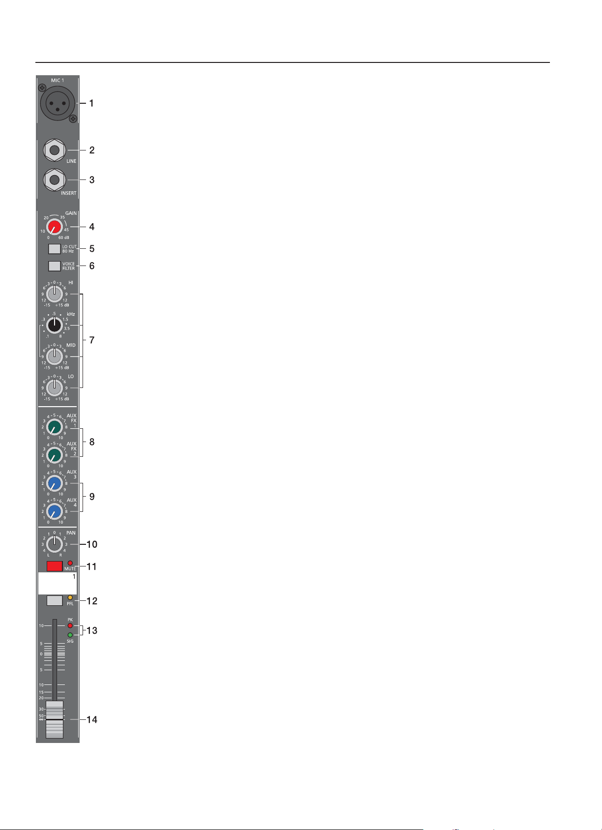
INPUT MONO
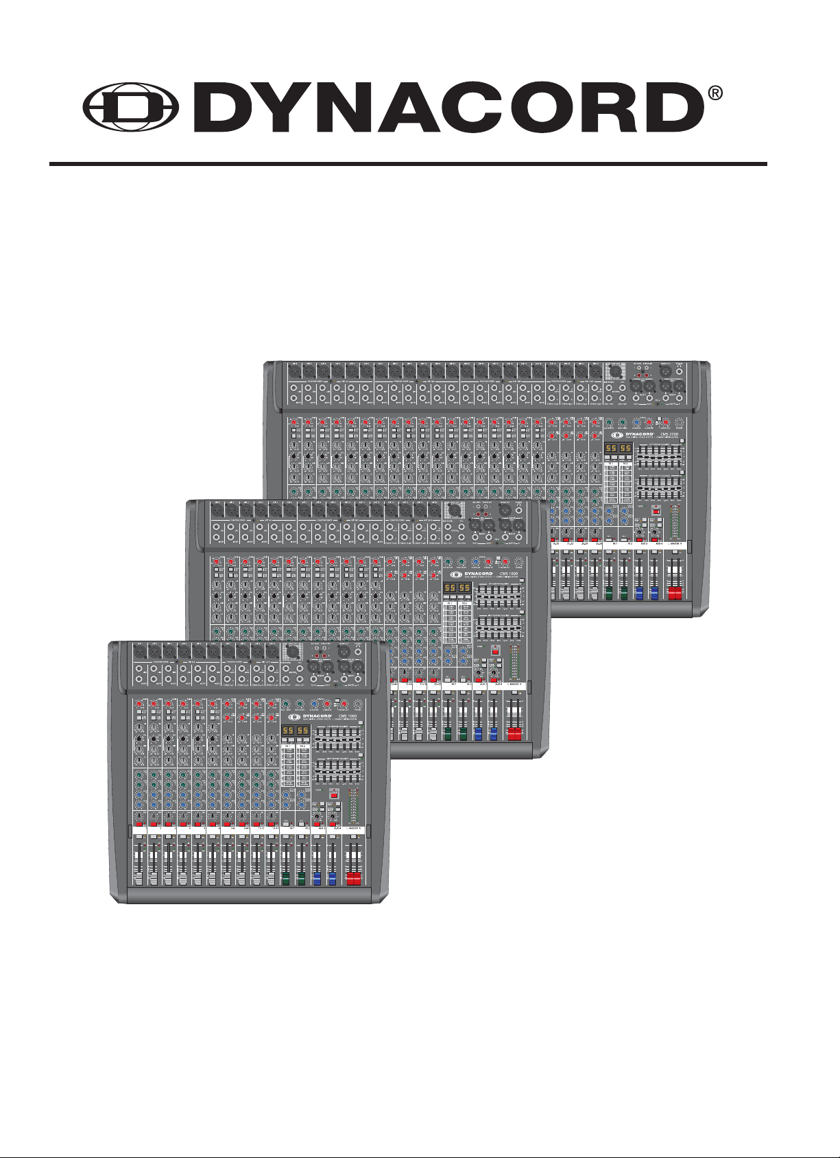
1. MIC
Electronically balanced XLR-type inputs for the connection of low impedance microphones like the ones
featured in state-of-the-art studio and live mixing consoles. This type of input stage provides extraordinary
low noise signal conversion at an extremely low distortion rate (typical <0.002%) even in the high frequency
range. Generally, any type of microphone can be connected as long as its pin assignment is in accordance to
the diagram as shown below. When condenser microphones are connected, you have to press the PHANTOM
POWER button, which is located in the input section. The microphone gets its operating voltage (+48) through
the mixer and you can forget about battery replacement times.
CAUTION: Make sure to always connect the microphones before turning on the phantom power or switching
the CMS on with phantom power being activated. This is the only way to prevent your microphones from
being damaged. Also make sure to engage the STANDBY button in the master section to safe yourself and
your environment from nasty power-on noise. Simultaneous connection of condenser type microphones and
dynamic microphone models is generally possible with phantom power being activated. Before you do so,
please consult the manual of the concerned microphone. The MIC input accepts levels between –60dBu …
+21dBu – depending on the setting of the corresponding gain control. Because of their low impedance design
and the possibility of phantom power these XLR-type inputs are mainly suitable for microphone applications.
However, cascading additional mixing consoles or connecting FX units, keyboards or other electronic
equipment is possible as well. Because of improved impedance and level matching using the LINE level inputs
when connecting this kind of equipment is preferable.
2. LINE
Electronically balanced inputs for the connection of electronic instruments, such as keyboards, drum machines,
E-guitars and E-basses with an active output, as well as all other high level signal sources, like additional
mixers, FX units, CD players, etc. The LINE input accepts levels between –40dBu … +41dBu. The connection
of balanced or unbalanced signal sources is established through monaural or stereo phone plugs, assigned
according to the diagram below. If the device that you want to connect has a balanced output stage, the use
of balanced cables with stereo phone plugs is preferable. This type of connection is greatly insensitive to the
induction of external noise or HF interference.
Do not connect signal sources to LINE and MIC inputs at the same time. The signals would interfere with each
other, resulting in level reduction.
Note: Please, do not connect E-guitars or E-basses with passive, high impedance outputs directly to a LINE
input. These inputs, like Line level inputs of mixers from other manufacturers, are meant for the connection of
the relatively low source impedance of electronic instruments. The reproduction of the instrument’s original
sound characteristics will be unsatisfactory. Connect those instruments using a special transformer or preamplifi er with very high input impedance. Musical instruments with an active electronic output (battery-powered)
can be connected without second thoughts.
When connecting signal sources, please make sure to set the corresponding channel faders or at least
the two master faders to their minimum positions or engage the STANDBY button. This will save you,
your audience, and the equipment from extensive wear from unpleasant pops.
5
INPUT MONO
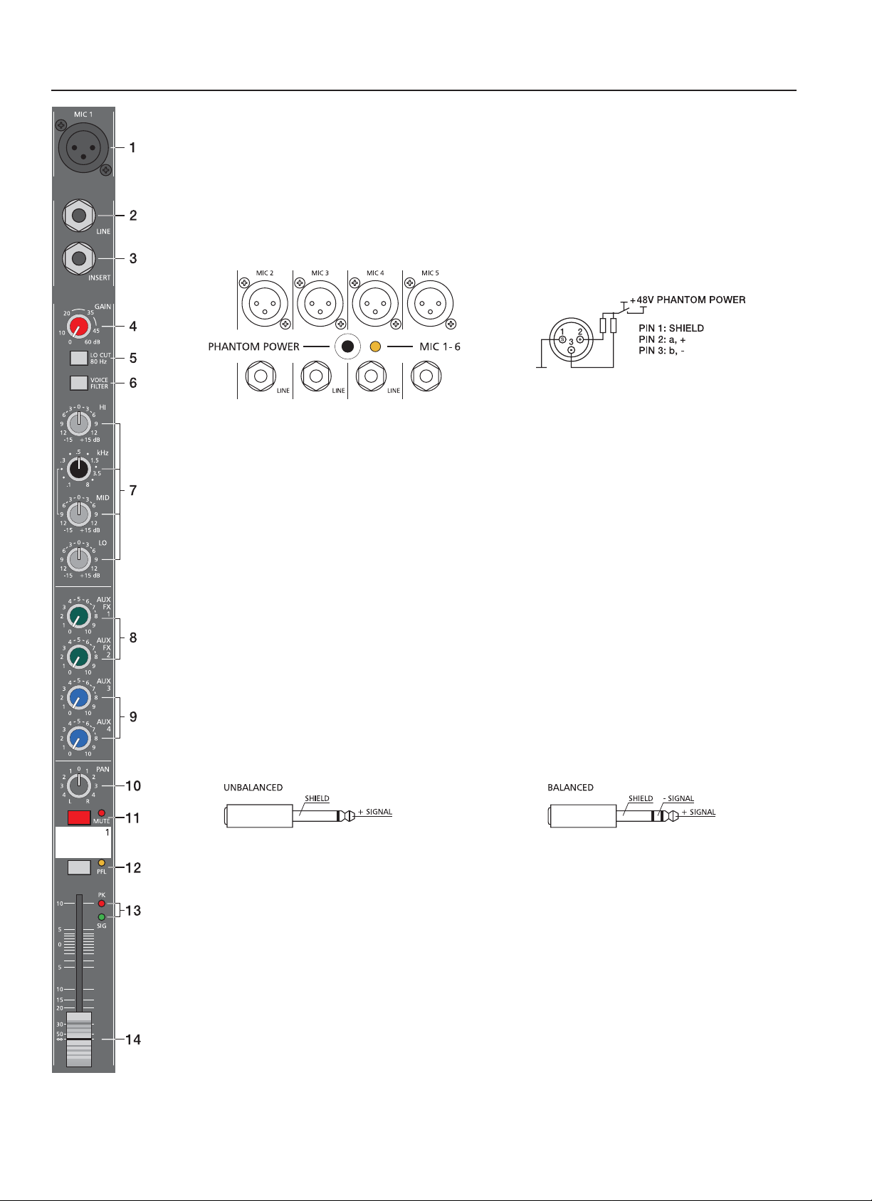
3. INSERT
Stereo phone jack with breaker function and with the low impedance output being assigned to the tip (send) and
the high impedance input (return) to the ring. This jack allows the connection of external FX units, compressors,
limiters, EQs, de-noisers, etc. into the corresponding channel’s signal path. The insertion point is post gain
controls, Lo-Cut fi lters, and voicing stage but pre sound shaping section and channel faders. You have to use a
stereo phone plug (Y-cord) – according to the following diagram.
When using the insert socket as a DIRECT OUT (Pre EQ), the stereo phone plug’s tip and ring have to be short
circuited, so that the audio signal is not interrupted. If you are using a monaural phone plug instead, you will
get a DIRECT OUT with breaker function – the audio signal can be output but the internal signal fl ow inside the
channel’s signal path is interrupted.
4. GAIN
Rotary control for adjusting a MIC/LINE input’s sensitivity. These controls let you optimally adjust the incoming
signals to the mixer’s internal operation level. Cautious adjusting offers the benefi ts of improved S/N-ratio and
provides you with the full bandwidth of the CMS’s outstanding sound capabilities. On the XLR-type connectors
an amplifi cation of 0dB is achieved when the control is set all the way at its counterclockwise rest and +60dB
when the control is set at its clockwise rest. Especially when dealing with very low input levels – during vocal
recordings or when the sound source is located in a distance – the high gain is extremely profi table. Using the
LINE-input, the signal is generally attenuated by –20 dB while maintaining the total adjustment range of 60dB.
The LINE-input’s unity gain – no amplifi cation (0 dB) – is achieved at the 20dB mark. The following is meant as
a short introduction to assist you in determining correct input levels:
Setting Instructions:
1. Set the gain control and the corresponding channel fader to their minimum values.
2. Connect the desired sound source (microphone, musical instrument, etc.) to the desired MIC or LINE
input.
3. Start the reproduction of the sound source at the highest volume level to be expected – respectively sing or
speak as loud as possible directly (short distance) into the microphone.
4. While doing so, adjust the input level using the gain control, so that during the loudest passages the PEAK
LED is just not lit, but the SIGNAL present LED lights constantly.
This is the basic channel setting, leaving you with at least 6dB of headroom, i.e. you have at least a range of
6dB before signal clipping occurs. In case you intend to make further adjustments to the channel’s tone control
setting, you should perform steps 3. and 4. again afterwards, since changes in the sound shaping section also
have an infl uence on the channel’s overall level.
6
INPUT MONO
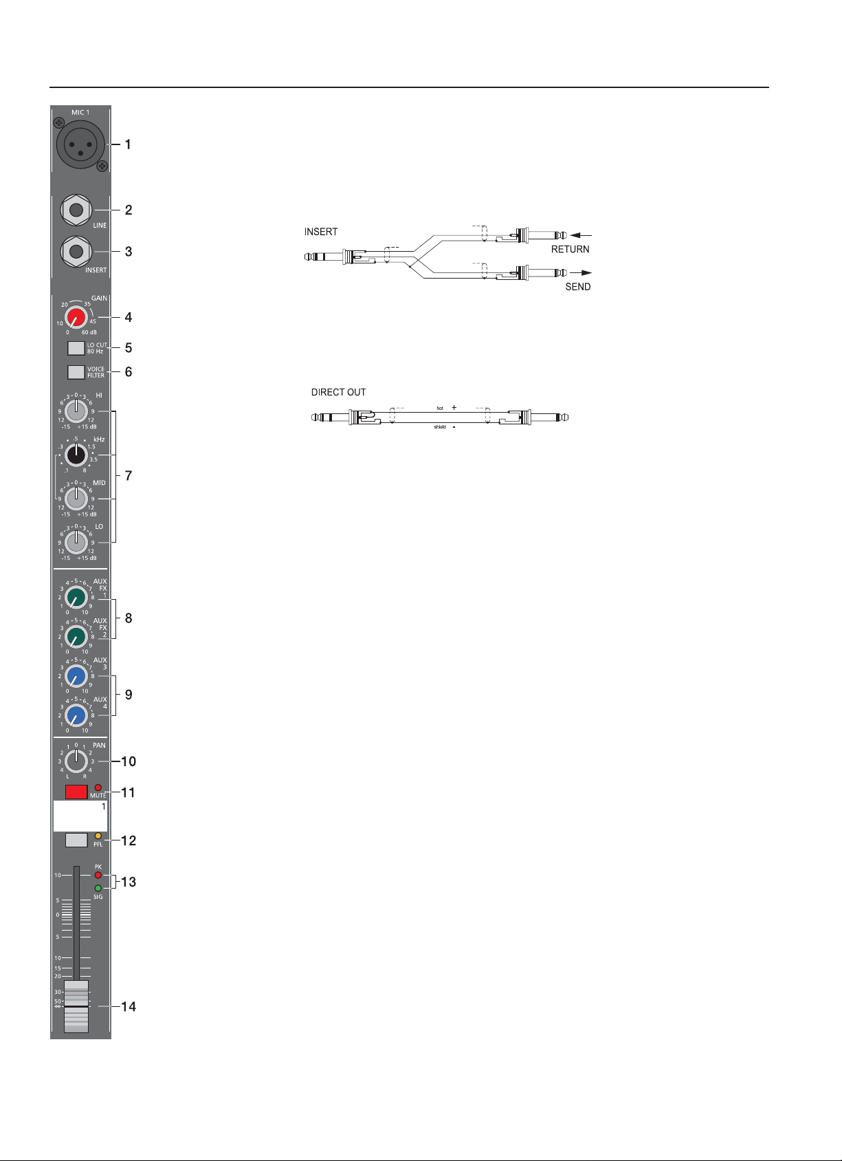
5. LO CUT 80 Hz
When the LO CUT switch is engaged, frequencies below 80 Hz are
attenuated (18dB octave slope). In most cases it is good advice to
use the LO CUT fi lter with microphone channels, since it effi ciently
suppresses popping sounds, rumbling noise and low-frequency
feedback. The only exceptions are kick drum and bass. Sometimes
it can be also very effective to combine the LO CUT fi lter with the
voicing fi lter, for instance to provide vocals with more “body”, without
getting additional low pitched noise. Activating the LO CUT and
raising the bass level (LO EQ) provides you with a richer sound,
without additional rumbling or low-frequency popping noise. Another
welcome side effect is, that the power amplifi er and the loudspeakers
connected to your sound reinforcement system do not get “polluted” with unnecessary low-pitched interference.
Y our audience will be thankful for the use of the LO CUT fi lter, too, since in this way they can enjoy a truly clear ,
natural, and powerful sound performance.
5
0
-5
-10
-15
-20
-25
-30
-35
20 100 1k 10k 20k
6. VOICING FILTER
This button activates a special asymmetric microphone fi lter, which
can be used in addition to the channel EQ. The voicing fi lter enhances
the fi rst harmonic oscillation and the treble of the human voice while
slightly attenuating the mid frequency range. This voice shaping
method provides powerful vocals that are clearly emphasized from
the rest of the mix. Ordinary third or octave band equalizers do not
provide this kind of “pre-shaping”. The use of this fi lter is not restricted
to vocals only . Horns, woodwinds, and other acoustic instruments can
profi t from the voicing fi lter as well. We leave it entirely up to your
creativity and imagination to try the VOICE fi lter with as many different
sound sources, as you want.
20
15
10
5
0
-5
-10
-15
-20
20 100 1k 10k 20k
Normally, you do not have to fear any problems with the occurrence of feedback.
7. EQ Section
The mixer’s EQ section allows very differentiated shaping of the incoming audio signal within miscellaneous
frequency bands. Turning one of the EQ level controls to the right enhances/amplifi es the corresponding
frequency range while turning it to the left lowers/attenuates the signal of that specifi c frequency band. Before
you begin to alter the sound, all EQ controls should be set to their neutral position, i.e. their marker points
straight up (locked in place). Try not to set the EQ controls to extreme positions. Usually, minor changes are
totally suffi cient and produce the best results in the overall sound. Y ou should use the natural reproduction as an
orientation mark and rely on your musically trained ear. Moderate use of the MID control is the best remedy to
avoid acoustical feedback. Especially in this frequency range you should try to avoid excessive enhancement.
Lowering the level more or less in this band will provide you with high amplifi cation rates without feedback. Use
the LO control according to your pleasing, to add more “punch” to the sound of a kick drum or “body” to the
vocals. Use the HI control in the same way to provide cymbals and the human voice with more treble and a
more transparent sound. The MID EQ section offers parametric EQ-setting via separate rotary controls for the
adjustment of level (MID) and frequency band (kHz) in the range between 100 Hz and 8 kHz.
LOW/HI EQ
20
15
10
5
0
-5
-10
-15
-20
20 100 1k 10k 20k
MID EQ
.1kHz & 8kHz
7

INPUT MONO
Adjustments in the MID frequency range are certainly the most effective way to shape the sound. As a matter of
fact, determining the correct center frequency is not always as easy as it seems. Here is one method – amongst
others – how to quickly fi nd the right setting of the parametric EQ for your application:
Setting Instructions:
1. Slightly lower the channel fader to avoid feedback.
2. Position the MID rotary control in the range of +9dB … +15dB.
3. Play the desired sound source or talk into the microphone.
4. While doing so turn the frequency rotary control (kHz) slowly from left to right.
5. Surely and within no time, you will detect the frequency range that is not to your liking or causing
feedback.
6. Leave the frequency control in this position and turn the MID control to the left until the sound is natural or
to your liking.
8. AUX / FX 1/2
The AUX/FX controls allow adjusting individual amounts of the input signals to be routed to the integrated FX1
or the FX2 effects units. The signal path is split post volume fader – POST FADE – so that the fader setting
also infl uences the amount of the signal that is fed to the FX units. Using the AUX/FX controls lets you easily
assign special effects to groups of musical instruments or vocals. For example, you can assign a short reverb
effect of the FX1 unit to the lead vocals and a combined effects program – echo, hall, and chorus – via FX2
to the background vocals. To determine the desired intensity of each effect, you should start with the controls
set at their center and make individual adjustments from there on. Please monitor the PEAK LEDs in the
FX1/2 channels. The indicator should only light briefl y at the occurrence of high program peaks. If the indicator
lights constant, you should lower the send levels of the channels in which program peaks occur. For further
information, please read the paragraphs about the FX1/2 units. (In case you are not using the internal FX units
and/or you want to connect external signal processing units, the pre-mixed AUX/FX1/2 signals are outputted
via the AUX1/2 send jacks.)
9. AUX 3/4
AUX 3 and AUX 4 controls are primarily meant for establishing two independent monitor mixes. Using the
master section’s AUX PRE/POST switches allows determining whether the signals are split pre or post fader.
PRE-FADER: The audio signal that is present at the AUX control is tapped pre volume fader and therefore not
affected by the fader’s setting. This mode is mainly used for monitoring. Pre-Fader Monitoring is especially
preferable when monitoring and main mix need to be completely different from each other, e.g. when the
volume setting of particular musical instruments or vocals needs to be higher or lower than in the main mix. In
most cases the mixing console is placed somewhere in the audience area (FOH) and is being operated by an
experienced sound technician.
POST-FADER: The audio signal that is present at the AUX control is tapped post volume fader and therefore
affected by the fader’s setting. This mode is mainly used for establishing FX- or special monitoring mixes.
Using the POST-Fader method is recommended when the mixer is also located on the stage and you have to
operate it yourself. Setting all AUX3 or AUX 4 controls to their center position, the main mix is also present on
the monitor bus, giving you the opportunity to control the volume settings of each channel individually from the
stage. The overall volume of the monitor mix is set using the AUX3/AUX4 faders in the master section. If you
are using this option you should keep in mind that all volume changes made with the channel faders also apply
to the monitor mix, leaving you with a higher risk of acoustic feedback.
The Post-Fader Monitoring method provides the possibility of canceling channels of some instruments – like kick
or snare drum, which are in fact already very loud on-stage – from the monitor mix by turning the corresponding
controls all the way to the left.
8
INPUT MONO
10. PAN
This control determines the position of the connected sound source within the stereo image. When the control is
set at its center position, the audio signal is fed with equal levels to the L and R master busses. The PAN control
section is designed to maintain the essential sound pressure level, no matter at what position within the stereo
image the PAN control is set to.
11. MUTE
The MUTE button mutes the input signal post fader, including all AUX sends. PFL and Signal/Peak stay
functional.
12. PFL
Engaging the PFL button routes the audio signal to the headphones bus, so that it is present at the phones
output connector. The meter instrument in the master section is simultaneously switched, so that the left LEDchain indicates the level (in dBu) of the actually chosen channel, which allows optimally matching the level of
the signal source. The phones output volume does not dependent on the setting of the corresponding channel
fader (PRE FADER LISTEN), which provides the possibility to listen to or shape the sound of the selected audio
signal, without need to include it in the main mix.
13. SIGNAL / PEAK Indicator
The signal-peak indicator plays a key role when setting input levels. The PK (peak) LED of the CMS provides
optical indication of the risk of occurring overdrive before you would actually hear the distortion over the
connected speaker systems. As outlined in the setting instructions, the Signal-LED should blink in the rhythm of
the incoming signal. If this is not the case, you have to increase the gain. If, on the other hand, the PEAK LED
blinks frequently or lights continuously, the corresponding channel is likely to enter clipping and you have to
turn the gain control a bit to the left. The signal LED lights at –30dB and the peak LED lights at a level of –6dB
below clipping. Keeping an eye on the indicator during a performance is also a good idea, because some very
dynamically performing members of a band or changing keyboard setups can easily lead to channel clipping,
resulting in the degradation of the overall sound.
14. VOLUME
The channel faders set the volume of the corresponding channels, establishing an accurately proportioned
mix. The channel faders should be positioned within the range of –5dB to 0dB, leaving you with a degree of
control that allows the precise matching of relative big differences in the input levels of different channels. The
overall volume is set through the use of the master faders. Even though the channel faders offer an additional
amplifi cation of +10dB, we would like to advise you to exceed the +5dB mark only in very few exceptional
cases. If the mixer’s summing bus gets overloaded with too many high level input channels, despite its special
gain structure, the summing amplifi er could be driven into clipping. Lowering the setting of each channel fader
by about –5dB and increasing the overall output level by elevating the master faders is the wiser solution. The
proportion of the mix and the overall volume stay the same while the risk of clipping is banished.
9
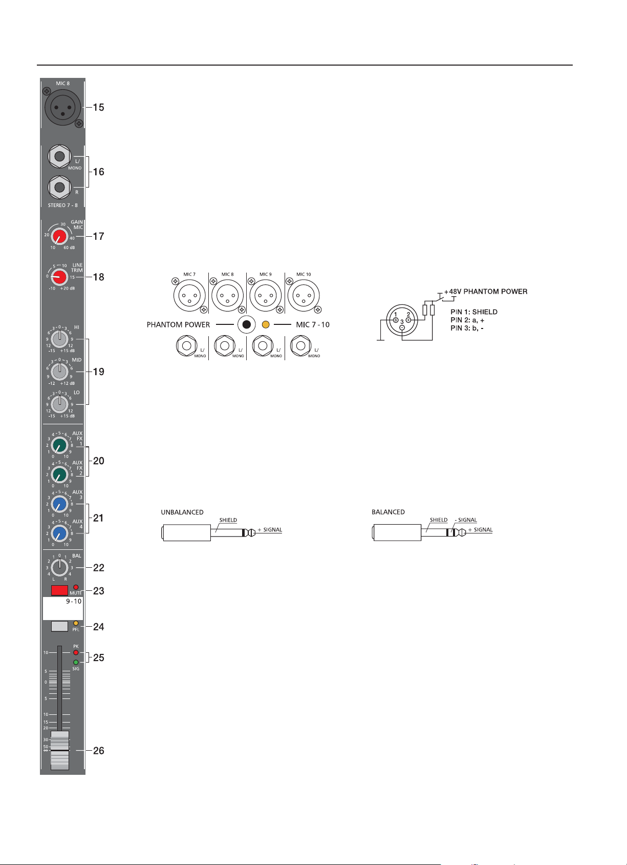
INPUT STEREO
Since most features – AUX controls, input connection and channel faders – of the STEREO INPUTS are
virtually identical to the ones of the MONO INPUTS we will not discuss their functioning in detail again. Thus, in
the following we only point out the differences and like to ask you to refer to the analogous paragraphs within
this owner’s manual describing the MONO INPUTS.
15.MIC
Like their monaural counterparts, the stereo input channels incorporate extensive circuitry and electronically
balanced XLR-type connectors for the connection of low impedance microphones. No matter if your setup is
more microphone-oriented or you have more line level sound sources to connect, you can always use the full
amount of input channels.
Dependable on its setting, the high-quality MIC input in the stereo channel is capable of handling levels between
-60dBu … +1 1dBu. Low-level circuitry architecture and phantom power (+48V) ability of this XLR-type input are
mainly aimed at the connection of microphones, making it not necessarily suitable for connecting Line level
appliances, like mixers, effects units, etc. Please use the provided LINE inputs instead. General functions and
usage of MIC inputs were already discussed in detail for monaural channels.
16. STEREO INPUT L/MONO R
Electronically balanced inputs for the connection of musical instruments with stereo output, like keyboards,
drum machines, E-guitars and E-basses with an active output as well as all other equivalent sound sources with
high level outputs, like additional mixing consoles, FX units, CD players, etc. The stereo LINE input is meant
for balanced or unbalanced sound sources with levels between –20dBu and +30dBu. For the connection of
external devices you can use monaural or stereo phone plugs, which are in accordance to the diagram below. If
the external appliance is equipped with a balanced output stage, using balanced cables and plugs is preferable,
since this type of connection provides improved shielding against HF interference and external noise.
In case you want to connect a monaural sound source to a stereo input channel, you just have to plug it into the
L/MONO input. The signal gets internally routed to both channels.
17. GAIN MIC
Control for adjusting the MIC inputs’ sensitivity, providing the possibility to optimally match the incoming signals
with the mixer’s internal operation level. The GAIN MIC control in the stereo channel is only active for the XLRtype input.
For further information about setting and functioning of these controls, please refer to the chapter GAIN of the
MONO INPUT description within this manual.
CAUTION: The GAIN MIC controls of all inactive microphone inputs should always be set to its minimum
position. Otherwise the noise of any microphone input that is not in use gets added to the audio signal of the
corresponding LINE input, which could lead to unnecessary extra noise at the main output, becoming clearly
audible in program breaks.
10
INPUT STEREO
18. LINE TRIM
Control for matching incoming line level signals to the mixer’s operating level. The total adjustment range is
30dB. Unity gain – no amplifi cation (0 dB) – is achieved at the 0dB mark. The control offers level reduction of
–10dB or amplifi cation of +20dB. This range allows the connection of most professional, semi professional, and
hi-fi sound sources. For further details on how to set the LINE TRIM control, please refer to the description of
gain controls in monaural channels.
If your sound source is a keyboard connected to one of the stereo inputs, make sure that no split zones or layers
with channel separation are activated. Otherwise, the stereo channel mapping will appear like it is set on the
keyboard – the lower layer in the left and the top layer in the right channel – and you will not have the opportunity
to re-position the sound in the overall stereo image, unless you connect the keyboard output to two adjacent
monaural input channels, leaving you the option to place the sound in the fi nal mix via PAN controls.
One more tip, in case you desperately need another input and all channels of the CMS are already in use: The
microphone input and the phone plug-type inputs are electrically totally separated from each other. Each input
is equipped with its own gain control – respectively trim control, providing you with the possibility to connect
a LINE level sound source in addition to a microphone. Of course, the two sources share all other controls.
Consequently, separate adjustment is not possible.
This option is only meant as a subsidiary function and should only be used when there is absolutely no other
alternative.
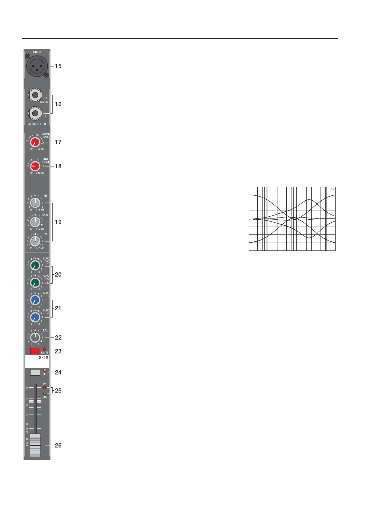
19. EQ SECTION
The mixer’s EQ section allows very comprehensive and effective
shaping of the incoming audio signal within miscellaneous frequency
bands. Turning one of the EQ level controls to the right enhances/
amplifi es the corresponding frequency range while turning it to the left
lowers/attenuates the signal of that specifi c frequency band. Before
you begin to alter the sound, all EQ controls should be set to their
neutral position, i.e. their marker points straight up (locked in place). Do
not set the EQ controls to extreme positions. Usually, minor changes
are totally suffi cient and produce the best results in the overall sound.
You should use the natural reproduction as an orientation mark and
rely on your musically trained ear. The moderate use of the MID control
20
15
10
5
0
-5
-10
-15
-20
20 100 1k 10k 20k
is the best remedy to avoid acoustical feedback. Especially in this frequency range you should try to avoid
excessive enhancement. Lowering the level more or less in this band will provide you with high amplifi cation
rates without feedback.
The STEREO channels’ EQ section is designed in a way that HI and LO controls provide a degree of control
that is equally adequate for LINE level inputs and microphones. The MID control is active in a comparably wide
frequency band around 2.4 kHz. Especially with microphone applications this range turned out to be critical, so
that slightly attenuating the mids offers excellent results.
20. AUX / FX 1/2
These controls determine the amount of the summed L and R signals that are sent POST-FADE to the AUX/FX
summing bus. For more details on the functioning of these controls, please refer to the INPUT/MONO section
of this owner’s manual.
21. AUX3/4
These controls determine the amount of the summed L and R signals that are sent to the AUX3 or AUX4
summing bus. Depending on the setting of the AUX PRE/POST switch in the master section, you can choose
whether the signal gets split PRE or POST FADER. For more details on the functioning of these controls, please
refer to the INPUT/MONO section of this owner’s manual.
22. BAL
The function of the stereo channels’ BAL control is comparable to the PAN control’s function of monaural
channels. For example, turning the rotary control all the way to the right outputs the right signal via the right
output while muting the signal of the left channel. When the control is set to its center position, the L and
R signals are present with equal intensity on the corresponding outputs. Whenever stereo sound sources
are connected to a stereo input, you should leave the BAL control at the center position or make only minor
adjustments in either direction. In case a microphone or another monaural sound source is connected, the BAL
controls function absolutely identical to the PAN controls in the monaural input channels.
11

INPUT STEREO
23. MUTE
The MUTE button mutes the input signal post fader, including all AUX sends. PFL and Signal/Peak stay
operational.
24. PFL
Engaging the PFL button sums the stereophonic audio signal of the corresponding input channel and routes
the resulting monaural signal to the headphones bus. You are able to listen to the audio signal via the phones
output. The meter instrument in the master section is simultaneously switched, so that the left LED-chain
indicates the level (in dBu) of the actually chosen channel, which allows optimally matching the level of the
signal source.
Simultaneously assigning as many channels as you want to the phones summing bus is no problem. The
volume levels of the individual signals are not affected by the setting of the corresponding channel faders (PRE
FADER LISTEN), which provides the opportunity to set the level and the EQ of a channel, without the need to
include it in the main mix, i.e. you can leave the channel fader down or even engage the MUTE button.
25. SIGNAL/PEAK
The stereo SIGNAL/PEAK indicator function provides independent analysis of left and right channel audio
signals. The respective highest level reading is indicated, assuring that neither one is already driven into
clipping. For further information on how to use this indicator most effi ciently, please refer to the description of
the monaural channel’s identical feature.
26. VOLUME
The channel fader is used to simultaneously adjust both levels (volumes) of the stereo signal. Functioning is
totally similar to the monaural channel fader, as previously described in the paragraph INPUT/MONO.
12
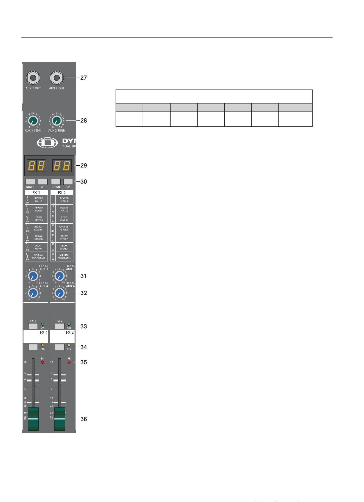
EFFECTS 1/2
FX1/FX2
The CMS offers two independently controllable, identically confi gured 24-bit stereo effect units – FX1
and FX2. Each unit provides 99 program presets, which can be selected by means of the UP/DOWN
buttons. The 99 presets are divided into groups according to their different effect structure, as printed
on the CMS and shown in the following listing.
FX1/FX2
1.......10 11.......20 21......30 31......40 41......50 51......60 61......99
REVERB
HALLS
The programs within each preset group are sorted in ascending order, where higher numbers
provide the same FX type with increased intensity. Presets 1 - 20 offer high quality reverberation
effect programs that are equally suitable for live performance, recording studio or home recording
applications. Program numbers 21 - 40 provide mixed effect types of echo/reverb and chorus/reverb
while the numbers 41 - 60 offer different delay effects. The last group from 61 - 99 provides different
fl anging, chorus, and doubling effects presets as well as special delay and reverb programs. In
factory-preset confi guration, after switching on the power of the CMS, FX1 starts with preset 05
(Large Hall 3 Bright) being selected while the FX2 unit is set to preset 55 (Delay Mono 250ms).
The two effect programs are equally suitable for live performance or recording applications and can
be used separately or together. Changing the start programs is possible at any time. For further
information, please refer to the paragraph Changing FX Start Programs.
REVERB
PLATES
ECHO
REVERB
CHORUS
REVERB
DELAY
STEREO
DELAY
MONO
SPECIAL
PROGRAMS
For testing, evaluating and selecting effect programs, please also refer to the supplementary
information of the page EFFECT PRESETS, which provides detailed description of all effect presets.
This listing contains all preset names together with the corresponding effect structure, fi eld of
application, and frequency characteristics. Take your time! Test all presets and select the ones that
are best suited for your specifi c application. Program number “0” selects a Slap Back Echo, which
is mainly for servicing and testing only, and therefore is not included in the effects listing on the front
panel. We would like to also attract your attention to the FOOTSWITCH connectors, which allow the
connection of footswitch pedals to remotely control the FX units’ EFFECT ON/OFF function. If your
footswitch features a LED – like the optionally available DYNACORD FS 11 does – this indicator will
light when the effect is activated (EFFECT ON).
Changing FX Start Programs
In factory shipping state, the FX units start with the programs 05/55. If you prefer different programs,
you can change and store the new settings in the programming mode. To assign new start programs,
please proceed as follows:
1. Switch the mixer ’s power on while simultaneously holding down the two DOWN buttons of FX1
and FX2.
2. “Prog” appears briefl y on the display. Programming mode is now active. A software-related side
effect is, that all buttons behave a bit slower than usual.
3. Release the two DOWN buttons and select the desired start programs.
4. Press the two UP buttons to store the displayed effect numbers as your new start programs. The
FX unit acknowledges the storing procedure by briefl y indicating “Prog” on the display.
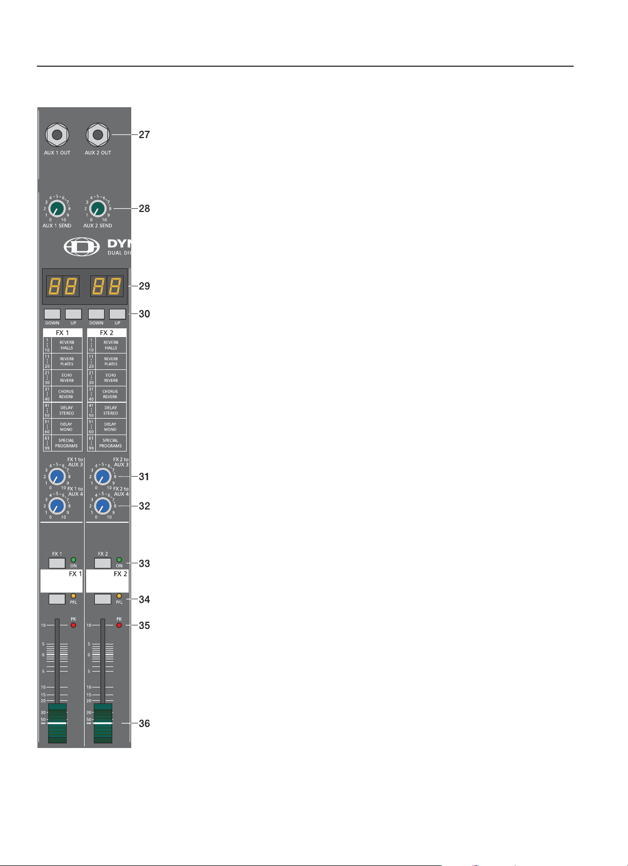
27/28. AUX1/2 SEND
The audio signal of the mix that you have established for the corresponding AUX/FX bus is present
at this socket, which, for example, makes it perfect for the connection of external FX units. Setting
the level is possible by means of the corresponding AUX SEND control. The external devices’ output
signals can be sent back to the CMS via stereo channel input.
13
EFFECTS 1/2
29. DISPLAY
The display always indicates the actual selected program number of the corresponding FX unit. The
display screen is covered with a protective foil to prevent it from being damaged during shipment.
Please remove the foil.
30. UP/DOWN
The UP/DOWN buttons are for selecting effect presets. Pressing and holding one of these lets you
scroll through the program numbers.
31/32. FX1/2 to AUX3/4
These controls allow adding the output signal of FX1 or FX2 to the monitoring channel. Experience
has revealed that the effect level in the monitor mix has to be lower than the level in the main mix,
since the distance between monitor speakers and artists is much shorter.
33. FX ON
This switch switches an internal FX unit on and the green LED lights. Please keep in mind that you
can also use an external footswitch for switching the FX unit ON. In this case, the LED also shows
the actual operational status of the FX unit. If you want to use a footswitch, the FX ON switch has to
be engaged fi rst. The corresponding FX unit is activated and you can use the footswitch to switch the
selected effect program on or off.
34. PFL
Engaging the PFL button routes the audio signal to the headphones bus, so that it is present at the
phones output connector. The phones output volume is independent of the corresponding FX fader’s
setting (PRE FADER LISTEN).
35. PEAK LED
These indicators signal if the internal FX units or the AUX 1/2 SEND signals are on the verge of
clipping. To achieve an adequate S/N ratio, please adjust the FX units’ input level as follows:
Setting Instructions:
1. Establish a “dry” mix – without effect settings – according to the previous descriptions.
2. Position the effect return fader of the corresponding effect channel at the –5dB mark.
3. Use the UP/DOWN buttons to select the desired FX program preset.
4. Press the FX ON switch.
5. Play (start the reproduction of) the sound source connected to the desired input channel and
adjust the desired amount of the FX signal, using the AUX/FX controls of this input channel.
Repeat this step for all input channels that you want to include in your effect mix.
6. Monitor the Peak LED so that it only lights frequently at highly dynamic signal peaks. When
clipping occurs, reduce the AUX/FX controls in the channels.
7. Use the FX to AUX control to add the effect mix to the monitor mix.
In case you are using a different effect setting for the second FX unit, you have to repeat steps 2 - 7,
respectively . Pay some attention to the peak indicators when operating your CMS to be able to quickly
interact when the signal levels exceed the normal range and enter clipping.
36. EFFECT RETURN
These stereo faders are used to determine the effect amount added to the main mix. In case you have
to set these faders at a position above the +5dB mark, the level of the FX unit’s input signal might be
too low. If that is the case, use the AUX/FX SEND controls to increase the input levels.
Use the FX faders to set the fi nal amount of the effects signal that is added to the main mix.
14
AUX3&4 / MASTER
Generally, the AUX3/4 channel is used for monitoring purposes. Depending on the setting of the
AUX3/4 POST buttons, it is also possible to confi gure the bus for the connection of an additional,
external FX unit.
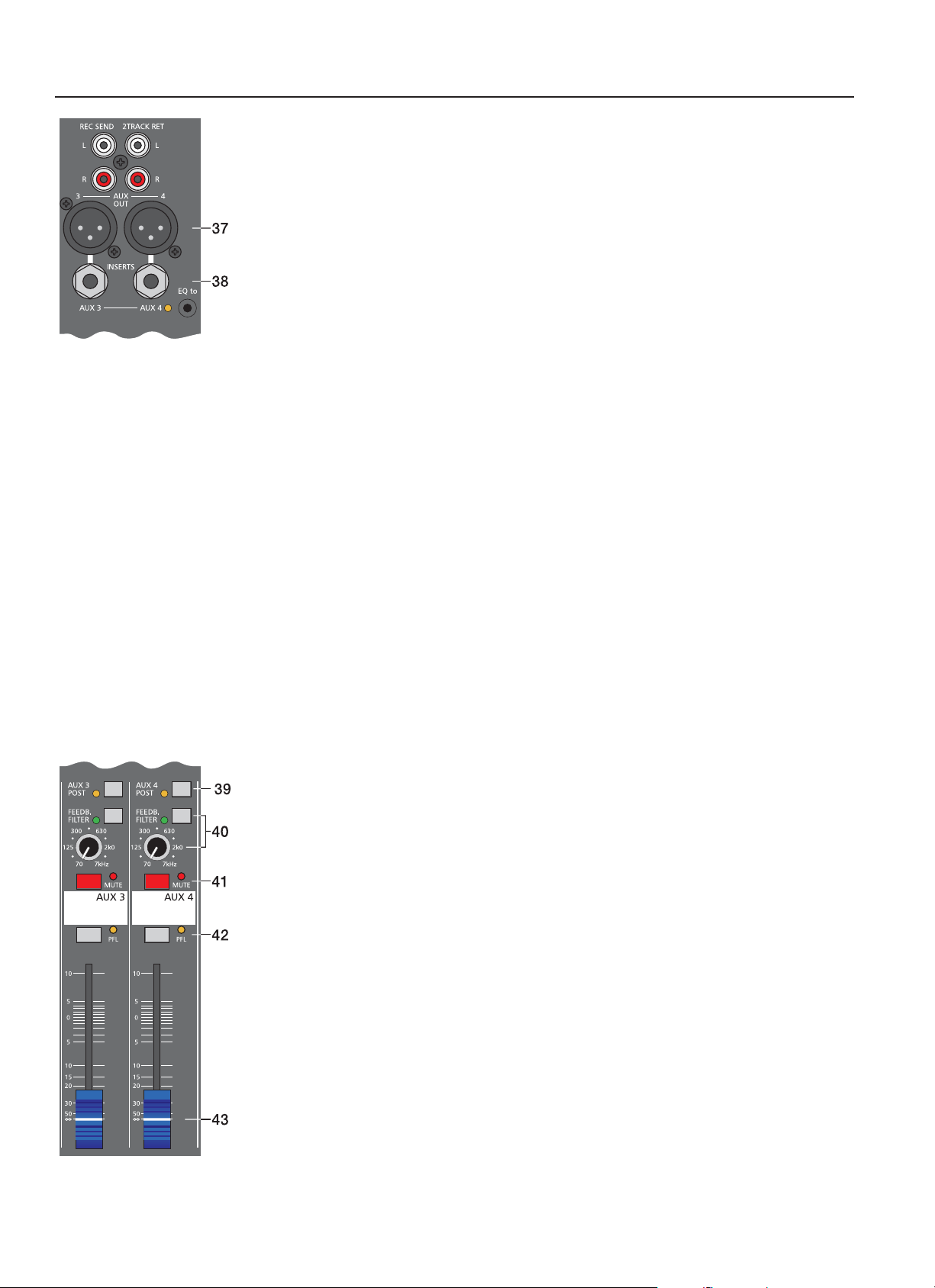
37. AUX3/4 OUT
This output provides connection for monitor power amplifi ers, active speaker systems or external FX
units. Using the AUX3/4 fader allows setting the output level of this electronically balanced output
in a wide range up to +20dBu. The AUX3/4 OUT – like any other XLR-type output on the CMS – is
relay-switched to prevent power-on noise when switching the mixer on or off. Use balanced cables
for the connection of external components whenever it is possible to prevent the induction of external
noise.
38. AUX3/4 INSERTS
The low impedance output of these stereo phone-type jacks for AUX3 and 4 with breaker function is
assigned to the tip (send) and the high impedance input (return) is assigned to the ring of the connector.
These jacks allow incorporating external third octave band or octave band EQs, compressors, limiters,
de-noisers, etc. into the AUX channel. The insertion point is pre AUX faders. The insertion point is
pre master faders. As well as with the inserts of the monaural input channels, different DIRECT OUT
functions can be accomplished. Please, also refer to the corresponding paragraph in the description
of the MONO INPUT.
39. AUX3/4 POST
As already previously described, this switch allows determining whether Pre- or Post-Fader signals
are present at the AUX3/4 channel. The corresponding yellow LED signals when the switch is
engaged and all input channel AUX3/4 controls are assigned post fader.
40. FEEDBACK FILTER
The feedback fi lter is a very narrow banded notch fi lter, which is only active in a range that is extremely
susceptible for acoustical feedback. The FEEDBACK fi lter rotary control sets the corresponding
frequency range. Pressing the corresponding ON button activates the fi lter. Several circumstances
and conditions have an infl uence on how sensitive or insensitive your system is for acoustical
feedback. The following notes are meant to assist you in avoiding feedback and you should take them
into consideration even before activating the feedback fi lter:
1. Avoid positioning the main speaker systems behind the microphones.
2. Switch off all microphones that are not in use.
3. Consider the microphones’ different polar patterns and characteristics, when placing the monitor
speakers.
4. Do not turn up the monitor system’s volume higher than actually necessary.
5. Try to avoid extensive equalization on channels that you want to include in your monitor mix.
6. Keep in mind, that a microphone “behaves” different when somebody stands right in front of it.
7. Position the microphones aiming at the sound source as direct as possible.
If you still have the feeling that the monitor system’s acoustic output is not suffi cient, after considering
the above mentioned precautions, you can use the FEEDBACK fi lter to attenuate the frequency that
tends to generate feedback the most. Therefore, you have to perform the following steps:
Increase the AUX3/4 (monitor) level until the limit is reached where feedback starts. The slightly
“hovering” sound that you hear is generated by the system itself. Switch on the feedback fi lter, turn
the rotary control and set it at the mark where the “sound” disappears. Switching the fi lter on and off
lets you easily check whether you tuned in the correct frequency. The feedback fi lter attenuates the
level of the corresponding frequency band by about 9dB. Since the fi ltered band is extremely narrow,
an alteration in the sound of your monitor system is hardly audible.
Caution: Please be extremely careful in driving the system just below the feedback limit. Careless
operation, resulting in feedback noise at high SPL, can cause severe damage to your speaker
systems and – even more important – the human ear.
41. MUTE
The MUTE button mutes the Aux-Send output signal. PFL signals are not affected.
15
AUX3&4 / MASTER
42. PFL
Through this button you can route the pre AUX3/4 fader signal to the headphones
bus. The signal is outputted for listening via the headphones output. The setting
of the AUX3/4 fader is not relevant for the signal’s volume (PRE FADER LISTEN).
The meter instrument in the master section is simultaneously switched, so that the
left LED-chain indicates the level (in dBu) of the actually chosen AUX channel.
43. AUX3/4 VOLUME
This fader controls the summed audio signal at the AUX3/4 SEND output. When
used for monitoring, this fader lets you control the volume of the monitor system.
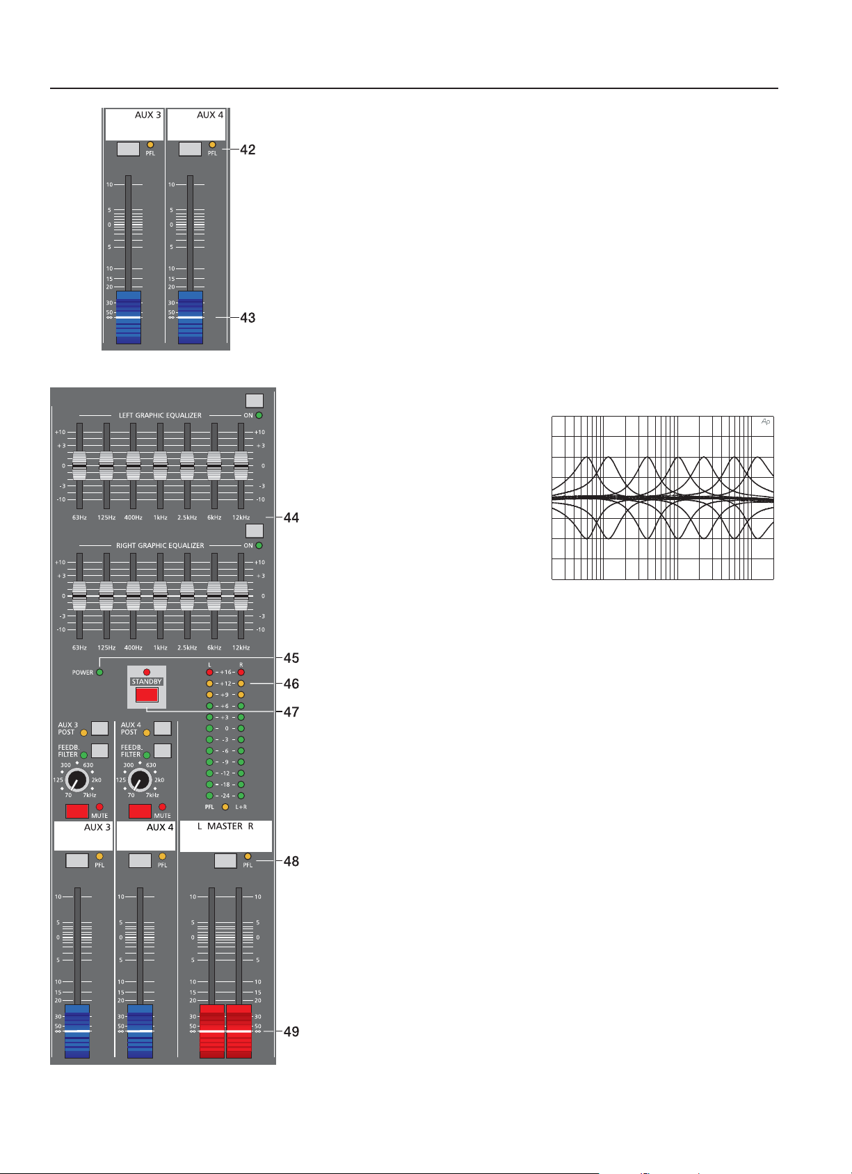
44. 7-BAND EQUALIZER
The two 7-band equalizers can either be used for the MASTER outputs or for
AUX3/4. Please also refer to paragraph 50 “EQ Routing”.
The EQ ON button activates the equalizer. The EQ’s insert point is post master
fader and pre main output. The EQ is bypassed when the EQ ON switch is not
locked in its “ON” position. Seven frequency bands offering 10 dB amplifi cation/
attenuation and a quality of Q=2 allow shaping the overall sound to optimally
match it to the acoustic conditions
of different locations.
Frequency ranges as well as
characteristics of the EQ faders
are very praxis-oriented. In case
you want to have a clear and highly
intelligible sound, which, as a side
effect, provides the cymbals with
more crisp, you should raise the
levels of the 12kHz or 6kHz band
a bit. If the MIDs are nasal you
should attenuate the mid range by
some decibels. To provide the kick
20
15
10
5
0
-5
-10
-15
-20
20 100 1k 10k 20k
drum with more punch you have to boost the low frequency range, using the 63Hz
or the 125Hz controls. In case the overall sound is undefi ned with too much bass,
lowering the levels of these two frequency bands will solve the problem. However,
especially with equalization you should be aware of the fact that in most cases
“less is more”. Thus, your fi rst choice should be to establish the mix using only the
input channel controls and see if you get a satisfactory result.
If so, you can use the equalizer for the AUX3/4, where in most cases, especially
when used for the monitoring, it is more needed.
45. POWER ANZEIGE
The POWER indicator lights when the CMS is operational. If the LED does not
light after switching the power on, please make sure that the mains cable is
correctly plugged in. If this is the case and the LED is still dimmed, please contact
your dealer.
16
MASTER
46. MASTER LED-DISPLAY
The CMS offers two 12-segment LED-chains for indication of left and right
channel output levels. The indication range of the LED-meter is 40dB, indicating
the levels (in dBu) that are present at the master outputs. The meter’s 0dB mark
is referenced to a 0dBu output signal at the mixer output.
Please mind that the signal indicated by the Master LED display is pre equalizer.
The master display is automatically switched to PFL-indication, once a PFLbutton is engaged (yellow LED lights). The left LED chain indicates the PFL-level
(the sum of all channels with PFL-buttons engaged) while the right LED chain
indicates the level of the summed master output. This display mode is useful for
checking the signal level of a single input channel, for example. When doing so,
please make sure that the only PFL-button engaged is the one of that specifi c
channel.
47. STANDBY
Pressing the ST ANDBY button mutes the output signals at the MASTER OUT L/R
and the MONO OUTPUT.
The STANDBY LED lights indicating that STANDBY operation has been
activated. All audio signals coming from the input channels are not output via the
MASTER OUTPUTS. However, audio signals connected via 2Track Return are
still outputted, providing you with a very comfortable solution to play intermission
music during performance breaks.
Caution: The monitor outputs AUX3/4 are still operational.
48. PFL MASTER
Engaging the master PFL-button, the PRE FADER stereo master signal is routed
to the phones bus, so that it can be monitored via headphones output. The
volume of this signal is not affected by the setting of the MASTER fader. The
meter instrument in the master section is simultaneously switched, so that the left
LED-chain indicates the level (in dBu) of the summed pre-fader L/R master signal
channel, which basically is the master bus level, while the right LED indicates the
level of the summed post-fader master output.
49. MASTER L + R
Level controls to adjust the output signals of the left and right main outputs
(MASTER).
Please, make sure to set the input channel faders or at least the master faders
to their minimum position, or to engage the STANDBY switch, before connecting
an external sound source to an input. This will save you, your audience, and the
equipment from unnecessary stress.
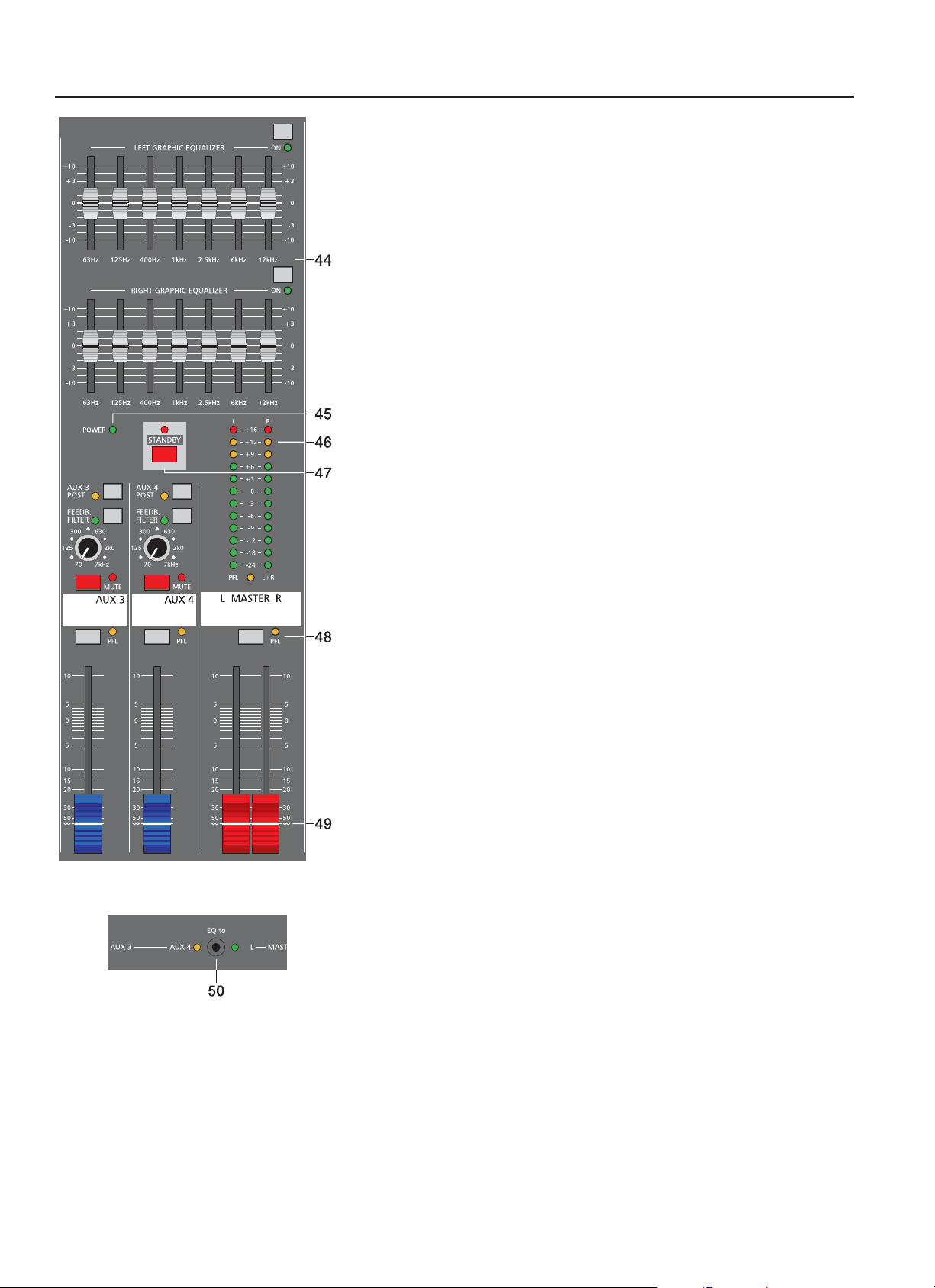
50. EQ Routing
This switch allows assigning the internal 7-band equalizer to the master or the
AUX3/4 buses wit two LEDs indicating the corresponding mode. In EQ to AUX3/4
mode (yellow LED lights) the “LEFT GRAPHIC EQUALIZER” controls the AUX3
channel while the “RIGHT GRAPHIC EQUALIZER” controls AUX4. In EQ to
MASTER mode (green LED lights) both equalizers control the MASTER outputs
as described in paragraph 44 “7-Band Equalizer”.
17
MASTER
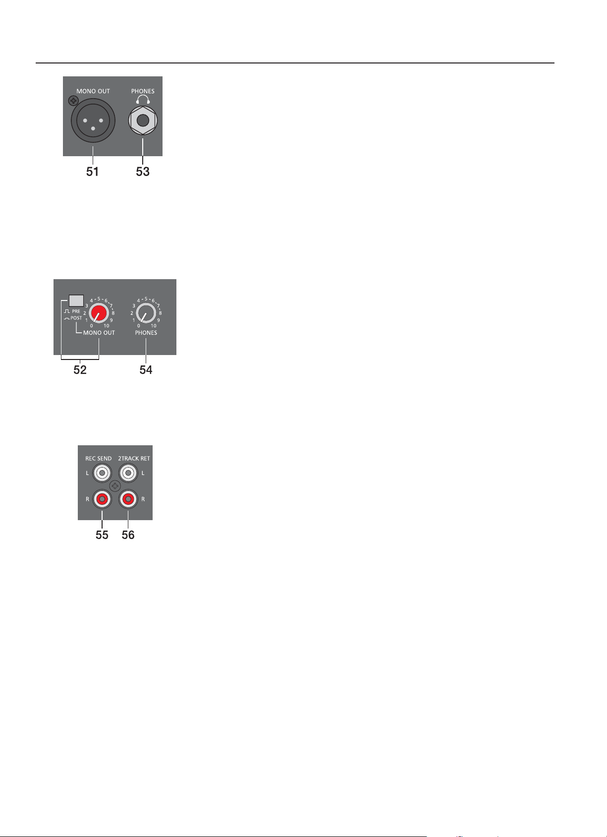
51. MONO OUTPUT
At this electronically balanced monaural output the summed L/R master audio signal is
present and can be used for additional monitoring, side fi ll and “next door” or Mono-PA
applications as well as for the connection of a delay-line or subwoofer. The MONO OUTPUT
– like any other XLR-type outputs on the CMS – is switched via output relay with a delay of
approx. two seconds after the mixer has been powered on, which prevents power-on noise
when switching the mixer on or off.
52. MONO OUT LEVEL & PRE/POST
This control allows setting the MONO OUT’s output level.
With subwoofer operation, “next-door”, monitoring or delay line applications a pre/postswitch able mono output often comes in handy.
PRE-FADER: The mono out’s signal is summed and outputted pre master faders.
The level at the mono out is independent from the master faders’ settings.
POST-FADER: The mono out’s signal is summed and outputted post master faders.
The level at the mono out depends on the setting of the master faders.
Of course, controlling the SUB’s level via master fader makes sense when using an active
monaural subwoofer. For monitoring applications, e.g. side fi ll on the stage, using the pre-
fader setting seems more reasonable.
53. PHONES STEREO phone-type jack for the connection of headphones with impedances
of 32 - 600 ohms. The audio signals of the channels with PFL buttons engaged are outputted
via this connector.
The phones output presents the master L/R signal when there is no PFL button engaged.
54. PHONES LEVEL
This control sets the volume of the headphones connected.
CAUTION: Make sure to set the control to its minimum position before connecting
headphones.
55. RECORD SEND L/R
These RCA-type connectors carry the PRE FADER master L/R signals, which are not
affected by the setting of the master faders and therefore mostly used for the connection of
cassette decks, open reel tape decks or DA T recorders for recording purposes. The nominal
level of the outputs is –10dBV and matches the professional industry standard as well as
most home recording applications. However, you should use the input gain control of your
recording device - as far as it is provided.
CAUTION: On many tape decks the input signal is directly carried through to the outputs.
In case you have connected both, REC SEND and 2TRACK RETURN, and the 2TRACK
to MASTER control of the CMS is set to anything but its lowest setting, the recorded signal
is included in the main mix again. The difference in delay of the two signals is responsible
for dropouts and general degradation in sound. In the worst case, activating the RECORD
button on your tape deck could lead to very unpleasant feedback noise. To prevent this
from happening make sure to set the 2TRACK to MASTER and the AUX3/4 controls to their
lowest settings (all the way counterclockwise).
56. 2TRACK RETURN L/R
Here you can connect tape decks, CD players, open reels or an additional SUB-mixer. The
signal is post master fader and post STANDBY switch, which allows playing intermission
music during performance breaks or checking the mix during rehearsals, using the
headphones. You just have to engage the STANDBY switch to mute all channel signals at
the main outputs. The 2TRACK RETURN signal however will pass unobstructed.
18
MASTER
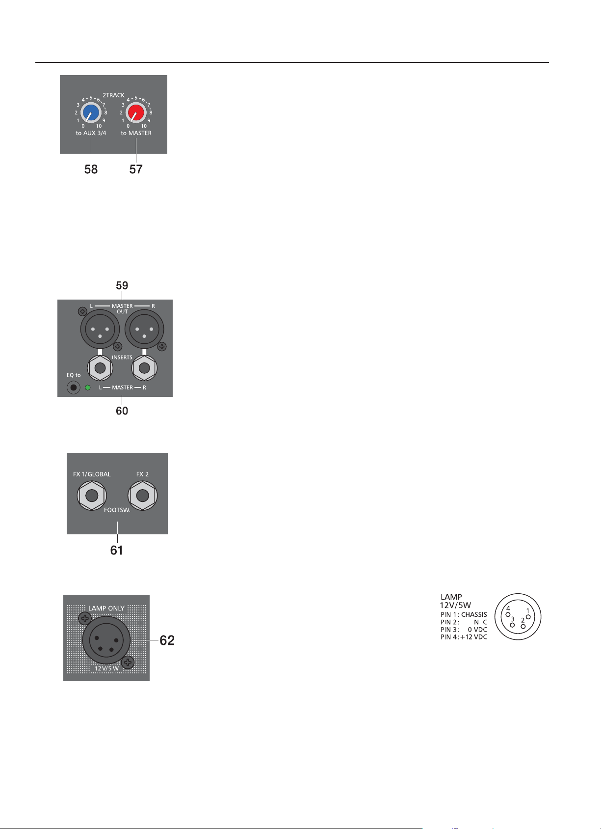
57. 2TRACK to MASTER
This control is used to add the 2TRACK signal to the main mix; post fader of the master
controls. Caution: When setting the level of the device that is connected to the 2TRACK
RETURNS – e. g. CD player, tape deck, etc. – always begin with the 2TRACK to MASTER
control set at its minimum setting; all the way counterclockwise. Otherwise, depending on
the output quality of the connected sound source, the outputted level can instantly “hit the
top”.
58. 2TRACK to AUX 3/4
The signal coming from the 2TRACK RETURN is internally summed and can be added to
the monitor bus using the 2TRACK to AUX3/4 control.
59. MASTER OUT
The mixer’s electronically balanced main outputs carrying the post master fader L/R signals
for connection of the main PA. The MASTER outputs are switched via output relay with a
delay of approx. two seconds after the mixer has been powered on, which prevents poweron noise when switching the mixer on or off.
Please also refer to the chapter “Setting up a standard PA system”.
60. MASTER INSERTS
Stereo phone jacks for left and right channels with breaker function. The low impedance
output is assigned to the tip (send) and the high impedance input (return) is assigned
to the ring of the connector. This jack allows incorporating external third octave band or
octave band EQs, compressors, limiters, de-noisers, etc. into the master’s signal path.
The insertion point is pre master faders. As well as with the inserts of the monaural input
channels, different DIRECT OUT functions can be accomplished. Please, also refer to the
corresponding paragraph in the description of the MONO INPUT.
61. FOOTSWITCH
Phone jack for the connection of an optionally available DYNACORD FS11 (110 693)
footswitch to switch the effect mode of the internal FX units on or off. To accomplish this
function, the FX1 and FX2 ON switches have to be engaged. To remotely control the effects
units using only a single footswitch, the FS11 has to be connected to the FX1/GLOBAL
connector. Both FX units are simultaneously switched. This function is useful for example
when switching from vocal performance to announcer. When remotely controlling the FX
units using two footswitches, one FS11 needs to be connected to the FX1/Global and the
other to the FX2 connector. Now, the two effects units can be switched independently, which
is mostly used to switch between different effects settings during a performance.
62. LAMP XLR
This XLR-type socket provides a DC voltage of 12V/5 watts
and is meant for the connection of a gooseneck lamp (litlite).
The output is protected against short-circuit and overload.
Please make sure that the illuminant used complies with
the here mentioned specifi cations and pin assignment
of the XLR-type connector. We recommend using the
gooseneck lamp (112 850) and the replacement illuminant (350 278), both available from
the DYNACORD accessory assortment. For further information, please consult your local
dealer.
19

REAR PANEL
POWER
Mains switch to turn the CMS on or off.
The CMS is operational once the POWER LED lights and outputs are activated
through automatic switching of the output relays.
Please make sure to set the master faders to their minimum position or engage the
ST ANDBY switch before switching the power on. This will save you, your audience,
and the equipment from unnecessary stress from unwanted loud signals or even
worse from acoustic feedback.
Please, proceed in the following order when switching your equipment on:
1. power on any external device, like an external equalizer, etc.
2. power on the CMS
3. power on external power amps, like main amp and monitor amp.
When switching the power off, please proceed in the opposite order.
20
CABLING
Cabling
The mains cord comes with the CMS. The quality of all other cables lies in your responsibility. Carefully chosen high quality cables
are the best precaution to prevent later problems during live operation. The following wiring alternatives are recommended to provide
trouble free operation of your system.
LF-Cables – Balanced or Unbalanced?
For LF-cabling – all the low current wiring – your best choice is the use of balanced cables (2 signal conductors + ground shielding)
with XLR-type connectors or stereo phone plugs. The cables should be step-on proof, shielded, and never longer than really needed.
Too many too long cables mostly lead to confusion and generate unnecessary problems. Of course, connecting unbalanced cables
with monaural phone plugs to the CMS’ in- and outputs is also possible and in most cases no interference will occur because of the
mixer’s superb grounding managing system. Generally spoken, balanced LF-cables are always preferable over monaural phone plug
cables. Today’s audio equipment – like amplifi ers, equalizers, FX units, mixing consoles, and even some keyboards – offers balanced
in- and/or outputs. In a balanced signal path the cable screen provides gapless connection of all metal parts, offering effi cient
shielding against the induction of external noise; mainly humming. Balanced cabling together with the common-mode rejection of the
CMS’ input stage effectively eliminates even residual interference. All inputs of the CMS provide balanced audio connection and high
common-mode rejection.
MASTER OUT L/R, MONO OUT and AUX OUT 3/4 are electronically balanced with relay-switching to prevent power-on noise.
AUX OUT 1/2 are laid out in GND-SENSING technology – a special pin-assignment of the output jacks, offering all advantages of
the balanced signal transmission, but lets you also connect monaural phone plugs without a problem. Nevertheless – as mentioned
above – when longer cables are involved, using stereo phone plugs and balanced cables are the better alternative. The diagrams
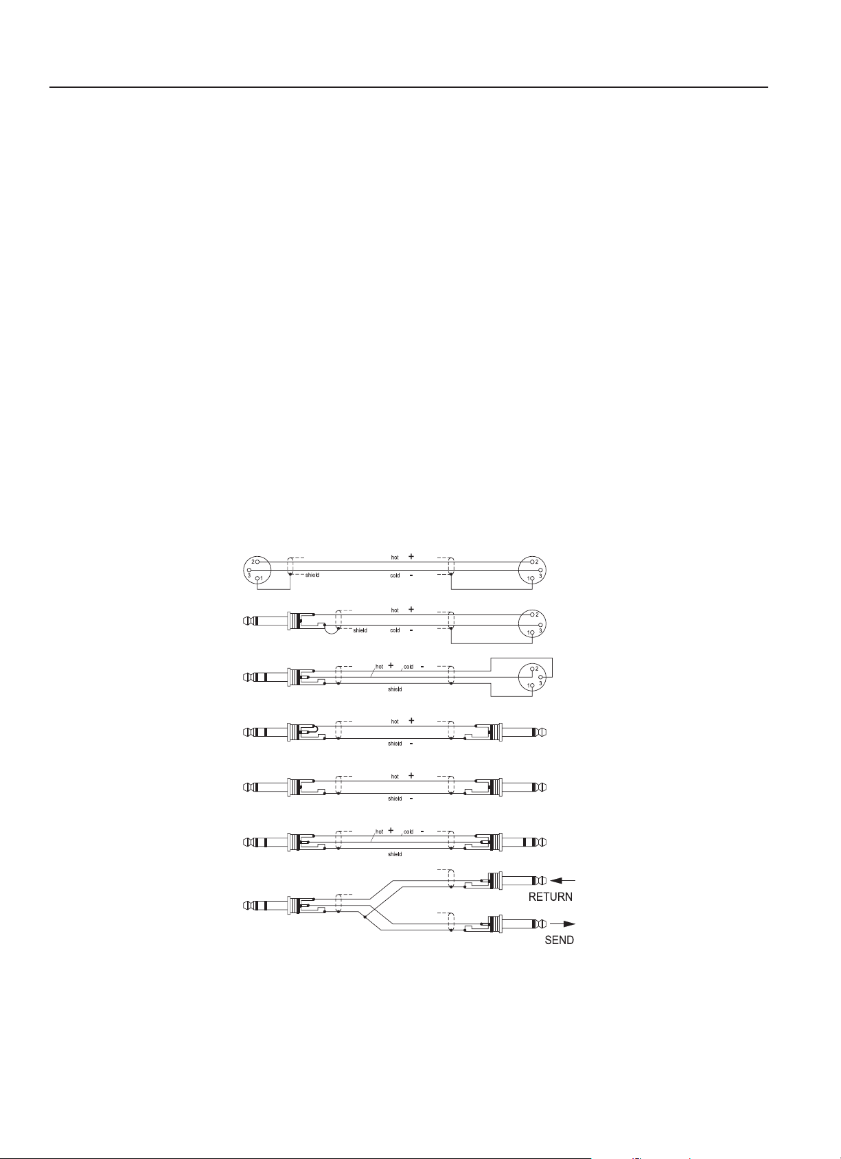
below show pin-assignments of plugs and cables that represent the best choice when used with the CMS.
MIC INPUT
All phone jack in/outputs
of the CMS
Channel Insert, MAIN Insert
or AUX Insert of the CMS
All phone jack in/outputs
of the CMS
Channel Insert, MAIN Insert
or AUX Insert of the CMS
balanced connection of microphones of the CMS
unbalanced
external equipment with XLRtype in/output jacks
balanced
Direct OUT via INSERT,
uninterrupted signal path
unbalanced
external equipment with XLRtype in/output jacks
balanced
Y-type cable for the connection
of external FX units and signal
processors with phone jacks
21

SETTING UP A STANDARD-PA SYSTEM
• Place the CMS and all connected appliances in a way that allows their unobstructed operation and connect the mains cord.
• Try to locate the best position where you want to place the main PA loudspeaker systems. If possible, the woofers should be
placed on the fl oor while the Hi cabinets’ most favorable position is above the Lo cabinets, on the same vertical axis. It is important
that the lower edge of the Hi cabinets is approximately at the same height level or slightly higher as the heads of the audience.
Either use the interconnection rods to mount the Hi cabinets on top of the woofer cabinets or, in case this kind of installation is not
possible or you are not using woofer systems, use separate speaker pole-stands instead.
• Do not place the left and the right speakers further apart than necessary. The less distance there is between the two speaker
“clusters” – the more compact the sound.
• Try to avoid positioning the main loudspeakers behind the imaginary line of microphones. Otherwise, if you have to drive the
system at higher sound pressure levels, the risk of feedback is very likely.
• After you have installed all microphone stands and all artists found their place, the best spot to install the monitor speakers is up
front facing the musicians and vocalists. However, please check if a microphone is directly pointing in the direction of a monitor.
In this case, change its position. You should also be aware of the individual characteristics of the employed microphones.
• Establish connections between woofers, monitor speaker systems and all other appliances as shown in the set-up examples.
Make sure to observe all notes provided in the owner’s manuals of all appliances in use. Make sure not to confuse channels by
accident.
• Connect all microphones preferably to the monaural inputs of the CMS and keyboards and other comparable sound sources to
the rest of the available inputs.
• Pull all faders down and engage the STANDBY button on the CMS to prevent unwanted feedback noise.
• First, switch on all external devices, then the CMS and at last power amplifi ers and active speaker systems.
• In case you have condenser microphones connected to the CMS and turn on phantom power by pressing the corresponding
PHANTOM POWER switch.
• Activate the CMS’ operational mode through pressing the STANDBY button again.
Sound Check
• First, adjust the input levels of the microphones that are connected to the monaural and/or stereophonic inputs on the CMS.
Please proceed as follows:
1. Set gain controls and channel faders to their lowest position.
2. Speak or sing as loud as possible into the microphone.
3. Use the gain control to adjust the level, so that even at loud passages the red PEAK LED does not light but the green
SIGNAL LED lights constantly.
• Adjust the tone controls of the monaural input channels:
1. Slide the channel fader and the master faders up a bit, so that the sound coming from the main speakers is heard.
2. Turn the MID control carefully all the way clockwise (+15dB). You should not hear any feedback.
3. Play the sound source or speak into the connected microphone
4. Turn the frequency control (kHz) slowly from left to right.
5. Surely and within no time, you will detect the frequency range that is not to your liking or causing feedback noise.
6. Leave the frequency control in this position and turn the MID control in the counterclockwise direction until the sound is
natural or to your liking.
7. If necessary, adjust the Hi and LOW controls, starting from their center position, until the sound matches your personal
taste.
8. Repeat steps 1 - 7 for all monaural input channels in use.
• In case you are also using the stereo input channels, adjust their levels in a similar way:
1. Set LINE TRIM controls, MIC gain controls, and channel fader to their lowest setting.
2. Play the corresponding sound source at the highest volume that is to be expected during the performance.
3. Use the LINE TRIM control to adjust the level, so that even at loud passages the red PEAK LED is not lit but the green
SIGNAL present LED lights constantly.
• Adjust the tone controls of the stereophonic channels:
1. Slide the channel fader and the master faders a bit up, so that you can hear the sound through the main speakers.
2. Set the EQ controls to their center position.
3. Play the corresponding sound source.
4. Starting from the center position, you can adjust the controls until the sound is to your liking. Please, keep in mind that
major alteration of the EQ-setting does not necessarily result in the improvement of the overall sound. Especially when
sound shaping is concerned, less can be more.
5. Repeat steps 1 - 4 for all stereo input channels in use.
• If musical instruments are connected at the monaural inputs, follow the descriptions above for adjusting the microphones.
• Make sure, that all channel faders, gain and LINE TRIM controls of unused input channels are at their minimum setting. In this
way you avoid unnecessary noise at the outputs.
22

SETTING UP A STANDARD-PA SYSTEM
Main Mix
Position the master faders in the range between –30dB and –20dB.
• Use the channel faders to establish a basic mix, so that individual sound levels relate to each other according to your personal
taste.
• The best range for the channel faders to be set to is in the area of –5dB to 0dB. In this way you are provided with enough
tolerance for later adjustment.
• Use the master faders to set the overall volume of the main PA.
• In case you want to include effects in the mix, please proceed as follows:
1. Set the effects return fader of the FX1 unit to the –5dB mark.
2. Use the UP/DOWN buttons to select the desired effect preset.
3. Press the FX ON button.
4. Play the sound source of the desired input channel and adjust the desired amount of the FX signal, using the FX controls
of the corresponding input channel. Repeat this step for all input channels that you want to include in the effect mix.
5. Make sure that the Peak LED only lights frequently at highly dynamic signal peaks. If it lights more often, reduce the input
level through use of the input channels’ FX SEND controls and increase the FX return level by setting the effects return
fader at a higher position.
6. If necessary, repeat steps 1 - 5 for the second internal FX unit (FX2).
Monitor Mix
For now, let’s presume, that you don’t use the CMS as FOH-mixer in the audience area but on-stage. The following procedure is
explained for AUX3. For setting AUX4, please perform the same steps analogous.
• Lower the setting of the AUX3 fader located in the master section.
• Engage the AUX3 POST button located in the master section.
• Set the AUX3 faders of all input channels in use to their center position, so that main mix and monitor mix are completely
identical.
• Carefully push the AUX3 fader up until a slight acoustic feedback is heard.
• Activate the FEEDBACK FILTER and adjust its control, so that the feedback noise disappears.
• Use the AUX3 fader to reduce the AUX3 level by about –6dB. This will provide you with enough “headroom” before feedback
during the performance, even then, when some microphone positions are changed disadvantageously.
• Use the FX to AUX3 controls to add the effect mix to the monitor mix, without infl uencing the main mix. Normally, the monitor
mix needs less FX than the main mix.
Let the artists perform some and check the sound coming from the main speaker systems from different angles and distances. If you
come to the conclusion that some corrections in the overall sound image are necessary , activate the 7-band equalizer and match the
sound to your liking. By doing so, you should keep in mind that during the performance the sound is going to be altered because of
the presence of an audience, which has a major effect on the acoustical condition of a location, the degree of fi rst refl ections, and
the absorption of low frequencies. If possible, you should check the “sound in the house” during the performance and – if necessary
– adjust it to the changed conditions.
And for the rest, we like to wish you lots of fun and success with your new CMS mixer.
23
SETUP EXAMPLES
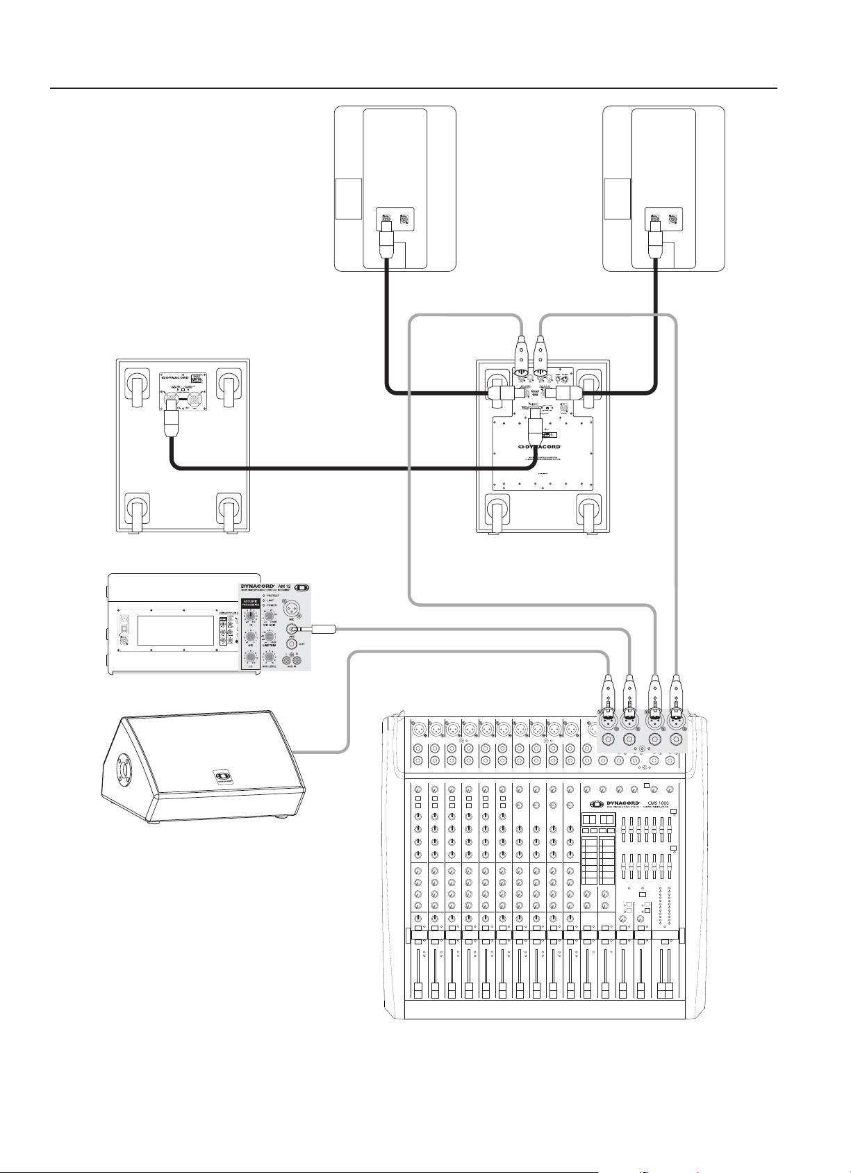
Optional
Subwoofer
Monitoring
Setting up a sound reinforcement system with active components. (CMS 1000 + active subwoofer with built-in power amps for top
cabinets + two AM12 active monitor speaker systems)
24
 Loading...