

Druck DPI 530 User Manual
K162 Issue No. 2
Druck DPI 530 Sub-Rack
Pneumatic Pressure Controller
User Manual
K162


K162 Issue No. 2
DPI 530 User Manual i
Safety
The manufacturer has designed this instrument to be safe when operated
using the procedures detailed in this manual. Do not use this instrument
for any other purpose than that stated. Do not apply values greater than
the maximum value stated.
This manual contains operating and safety instructions that must be
followed for safe operation and to maintain the instrument in a safe
condition. The safety instructions are either warnings or cautions issued
to protect the user and the equipment from injury or damage. Use
qualified* personnel and good engineering practice for all procedures in
this manual.
Pressure
Do not apply pressure greater the maximum safe working pressure to the
instrument.
Electrical Safety
This instrument is designed to be safe when using options and accessories
supplied by the manufacturer.
Toxic Materials
There are no known toxic materials used in this instrument.
Maintenance
The instrument must be maintained using the manufacturer’s procedures
and should be carried out by authorised service agents or the manufacturer’s
service departments.
Technical Advice
For technical advice contact the manufacturer or subsidiary refer to section
5.5.
* A qualified person must have attended a product training course given by
the manufacturer or appointed agent and successfully completed the
training course on this equipment.
K162 Issue No. 2
ii DPI 530 User Manual
Hazard, a warning highlighting a danger that would result
in injury. Also a marking on the instrument referring the
user to this publication.
Protective conductor terminal
Abbreviations and Symbols
The following abbreviations are used in this manual.
Note:
Abbreviations are the same in the singular and plural.
DVM digital voltmeter
FS full-scale
IEC International Electrical Council
inHg inch of mercury
kg/cm
2
kilogram per centimetre squared
kPa kilo Pascal
LCD liquid crystal display
mA milli Ampere
mm milli metre
psi pound per square inch
V Volt
VA Volt amp
Symbols
This product meets the essential protection requirements
of the relevant EEC directives. Further details of applied
standards may be found in the product specification.

K162 Issue No. 2
DPI 530 User Manual iii
Contents
Section page
1 Introduction ............................................................................... 1
1.1 Specification ............................................................................... 2
2 Installation ................................................................................. 5
2.1 Mounting ..................................................................................... 5
2.2 Source/Outlet Connections ........................................................ 5
2.3 Electrical Connections................................................................ 5
2.4 Pressure Connections ................................................................ 11
2.5 Fitting into Euro Rack ................................................................. 12
2.6 Applications ................................................................................. 13
3 Operation ................................................................................... 19
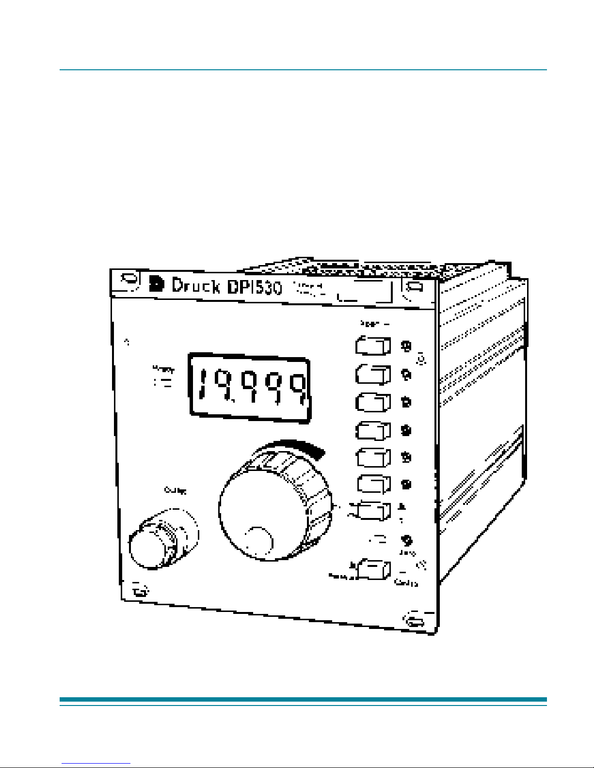
3.1 Description .................................................................................. 19
3.2 Controlling a Pressure ................................................................ 23
4 Calibration ................................................................................. 25
4.1 Accuracy Check.......................................................................... 26
4.2 Pressure Calibration Adjustment ............................................... 28
4.3 Remote Voltage and Current Set-point Calibration Adjustment 32
4.4 Assembly..................................................................................... 34
5 Maintenance .............................................................................. 35
5.1 Fault Finding ............................................................................... 35
5.2 Controller Adjustment ................................................................. 35
5.3 Leak Check ................................................................................. 37
5.4 Cleaning ...................................................................................... 38
5.5 Approved Service Agents........................................................... 39

K162 Issue No. 2
iv DPI 530 User Manual
Illustrations
Figure page
2-1 Rear Panel Connections ............................................................ 6
2-2 Ready Output .............................................................................. 10
2-3 Euro Sub Rack Fitting ................................................................ 12
Applications
2A Measure or Control Mode .......................................................... 14
2B Apply Fixed Set-points ............................................................... 14
2C V to P or I to P Conversion ........................................................ 15
2D Automatic Pressure Cycling ....................................................... 16
2E Pressure Switch Test Cycling .................................................... 17
2F Remote Controller with Ready Signal Interface ........................ 18
3-1 Schematic Diagram .................................................................... 21
3-2 Front Panel ................................................................................. 22
4-1 Access for Adjustments ............................................................. 27
4-2 Printed Circuit Board .................................................................. 29
4-3 Units of Pressure Measurement and Switch Positions ............ 31
4-4 Units of Pressure Measurement Potentiometers ...................... 31

DPI 530 User Manual 1
K162 Issue No.2
1 Introduction
The DPI 530 instrument is a fast response, closed loop, pneumatic
pressure controller. It is contained in a Euro sub-rack module that can be
mounted in a 3U high sub-rack. A push switch on the front panel enables
the instrument to operate in either the pressure measure mode or pressure
control mode.
Pressure is sensed by a transducer containing a silicon strain gauge
diaphragm with electronic thermal compensation and linearization. One of
five units of pressure measurement or percentage of full-scale can be
selected by switches on the rear panel of the instrument. A seven segment
LCD display shows, in the measure mode, the pressure value and, in the
control mode, the set-point value.
In the pressure control mode the set-point can be set by a centrallylocated, ten-turn potentiometer or by six independent preset span divider
keys. The preset value of each span divider is adjusted by individual
potentiometers. Each span divider has full control from the lowest
calibrated pressure to the span value. The controller uses pulse width
modulation to operate solenoid valves in an analogue control loop.
Remote control can be selected by switches on the rear panel. The
instrument can be remotely controlled by an analogue input signal of either
0 to 10 V d.c. or 0 to 20 mA d.c.
A pressure outlet port connection is located on both the front and rear
panels; all other connections are on the rear panel.

K162 Issue No. 2
2 DPI 530 User Manual
1.1 Specification
Range ..................................................................................... -1 to 20 bar
Accuracy ..................................................................................... ±0.1 % FS
Temperature effects.......................... combined zero and span shifts of <0.5%FS
(over 0 - 50°C)
Stability .............................................................. <0.025% rdg per 90 days
Controller stability ..................................................................................<0.01% FS
Maximum Safe Working Pressure ............................................................... 2 x FS
Pneumatic Supply ..................................................... clean, dry non-corrosive gas
source pressure ............................................................... 110 to 140% FS
vent pressure at least 5% FS less than the lowest controlled pressure
Pneumatic Connection
Outlet .................................................. front and rear panel G1/8 female
Reference ..................................................................... rear panel M5 female
Source .................................................................. rear panel G1/8 female
Vent .................................................................. rear panel G1/8 female
Five selectable units of pressure measurement and percentage of fullscale
bar, psi, kg/cm2, kPa, inHg, 0-100%FS
Electrical Safety
.................................................. meets EN61010-1 as applicable
The instrument must be connected to power supply with a protective earth/
ground conductor.
Power supply
Voltage .............................................................. 88 to 130 or 205 to 260 V
(set at manufacture)
Power consumption .......................................................................... 15 VA
Frequency................................................................................. 45 to 65 Hz

DPI 530 User Manual 3
K162 Issue No.2
Remote control
Voltage ............................................ 0 to 10 V, input impedance >500 kΩ
Current ................................................................ 0 to 20 mA, 100Ω sense
Display .............................................................................. 7-segment LCD
read-out .............................................................................................. 19999
resolution ................................................................ Better than ±0.005% FS
Electromagnetic compatibility
This instrument complies with European EMC directive and meets:
................................................................ EN 50081-1 (emissions)
.................................................................. EN 50082-1 (immunity)
Environmental
Temperature
Operating ................................................................................... 0° to 50° C
Storage ................................................................................ -20° to +70° C
Ingress protection ..................................................................... front panel to IP40
Dimensions ........................................................ 130 mm x 120 mm x 190 mm
(3U sub-rack, 24 HP wide)
Weight ................................................................................................. 2 kg

K162 Issue No. 2
4 DPI 530 User Manual
(blank page)
DPI 530 User Manual 5
K162 Issue No. 2
2 Installation
Installation must be carried out by suitably qualified installation personnel.
2.1 Mounting
This instrument is a 3U high, Euro sub-rack unit, designed to be mounted
in a Euro Sub-rack.
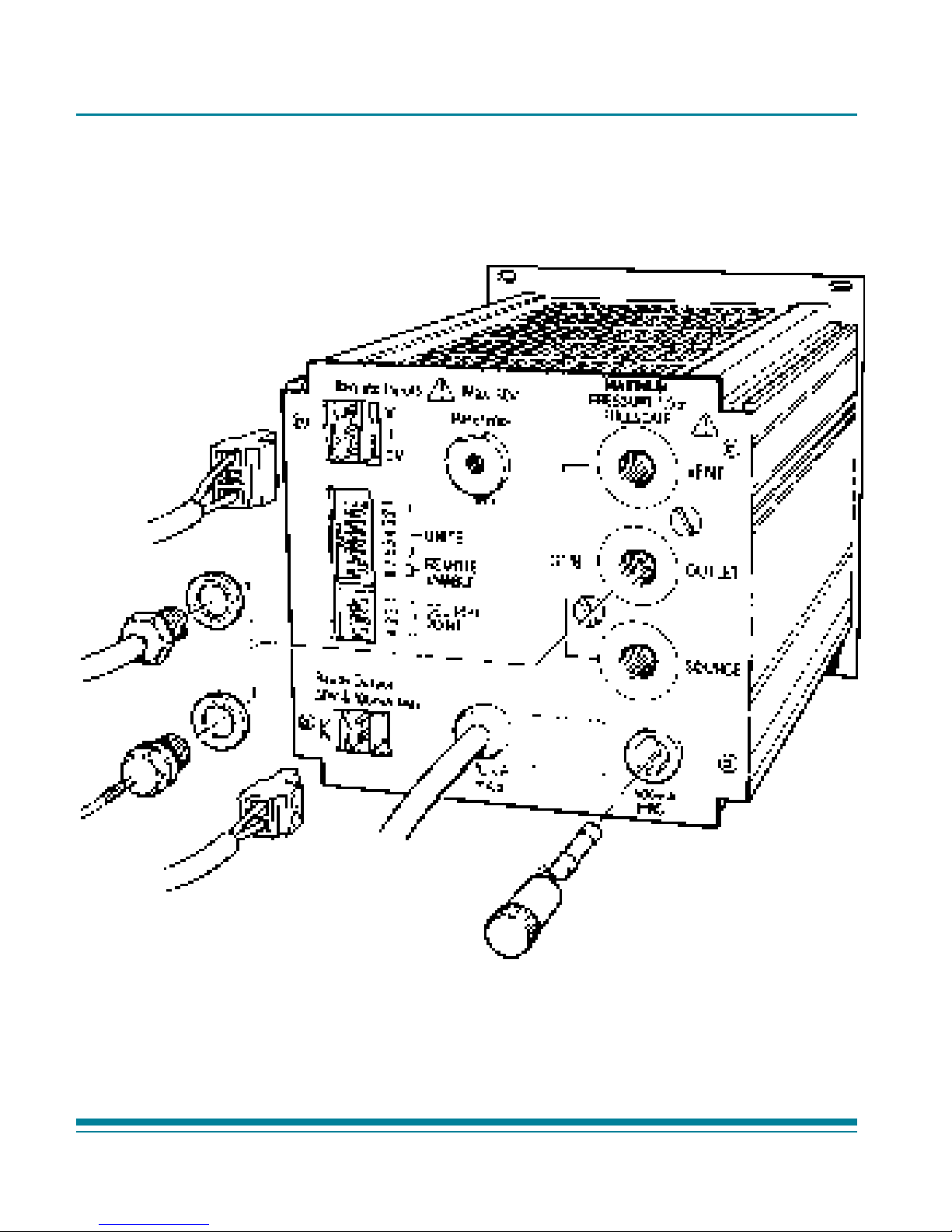
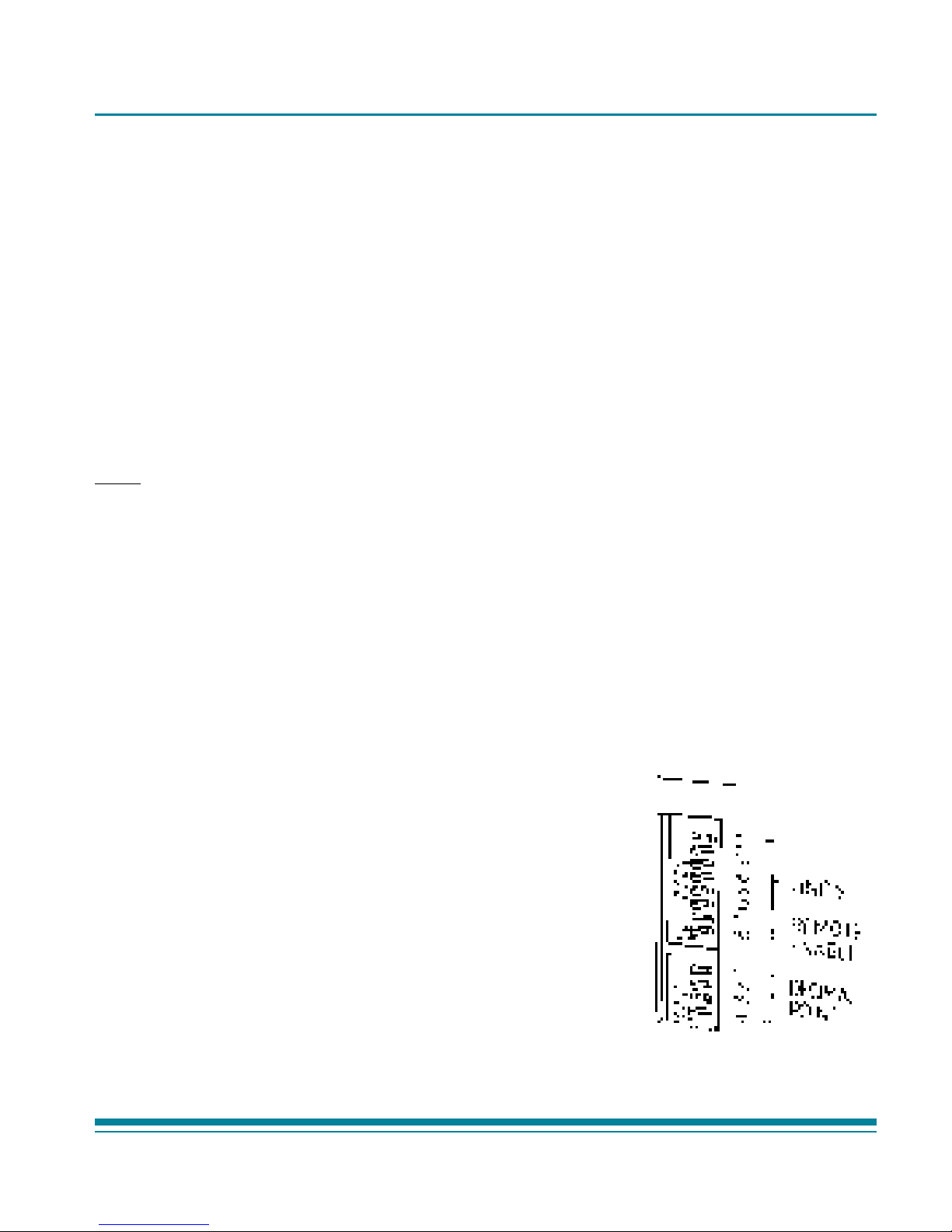
2.2 Source/Outlet Connections (Figure 2-1)
The common front and rear pressure outlet ports should have a blanking
plug fitted when not in use. All other the connections to the instrument are
on the rear panel. Figure 2-1 shows the rear panel pressure and electrical
connections.
Note: Allow enough cabling and piping for the instrument to be pulled out from the
sub-rack for access to the connections.
2.3 Electrical Connections (Figure 2-1)
Before connecting the instrument, make sure the DIP switches are set on
the rear panel for:
Units of measurement
Decimal point position on the display
Local or remote operation
WARNINGS
1 VOLTAGES IN EXCESS OF 30 V (RMS) A.C. OR 50 V D.C. CAN, IN
CERTAIN CIRCUMSTANCES, BE LETHAL. CARE MUST BE TAKEN
WHEN WORKING ON LIVE, EXPOSED CONDUCTORS.
2 ISOLATE THE POWER SUPPLY BEFORE CONNECTING THE
INSTRUMENT.
3 ISOLATE THE POWER SUPPLY BEFORE REMOVING THE
INSTRUMENT COVERS.
K162 Issue No. 2
6 DPI 530 User Manual
Figure 2-1 Rear Panel Connections
DPI 530 User Manual 7
K162 Issue No. 2
CAUTIONS
1USE THE CORRECT POWER SUPPLY SETTINGS. OPERATING VOLTAGE RANGES ARE
MARKED
ON THE REAR PANEL OF THE INSTRUMENT AND DETAILED IN THE
SPECIFICATION
.
2THE EARTH/GROUND CABLE (COLOURED GREEN/YELLOW) MUST BE CONNECTED TO
THE
POWER SUPPLY SAFETY EARTH/GROUND.
2.3.1 Setting the Pressure Measurement Units
Set the required pressure measurement units by selecting the applicable DIP
switches on the rear panel.
If necessary, change the front panel label to show the new units of pressure
measurement. This illustration shows bar selected.
Note: All other switches in the group (1-6) should be set to OFF (left).
Switch Pressure
Position Unit
1 On bar (for instruments <1bar)
1 On mbar (for instruments >1 bar)
2 On psi
3 On kg/cm
2
4 On kPa
5 On inHg
6 On 0 to 100% F.S.
K162 Issue No. 2
8 DPI 530 User Manual
2.3.2 Set-up Decimal Point Position
Set the decimal point position by selecting the switches on the rear panel
to on as shown below.
Note: All other switches in the (1 to 4) group should be set to OFF.
Switch Position Display
4 On 1.9999
3 On 19.999
2 On 199.99
1 On 1999.9
2.3.3 Enable Remote Control
For local control from the front panel potentiometer or span divider keys,
set switch 7 to ON and switch 8 to OFF.
For remote control from either an external voltage or current source, set
switch 8 to ON and switch 7 to OFF.
2.3.4 Power Supply Connections
A.C. power is supplied to the instrument through a captive power supply
cable. Figure 2-1 shows the cable and the related power supply fuse.
Connect the power supply cable to the power supply as follows.
Brown - Live (L)
Blue - Neutral (N)
Green/Yellow - Ground (Protective Earth)
For U.S. Versions
Black - Live (L)
White - Neutral (N)
Green - Ground(Protective Earth)
It is recommended that a power supply isolator is fitted between
the power supply and the instrument.
 Loading...