


OWNER’S MANUAL
CLASSIC EPA WOOD STOVE
US ENVIRONMENTAL PROTECTION
AGENCY PHASE II CERTIFIED WOOD
STOVE
Verified and tested following ULC S627 and UL 1482 Standards by:
Manufactured by : STOVE BUILDER INTERNATIONAL INC.
1700, Léon-Harmel, Québec (Québec) G1N 4R9
Tel : (418 ) 527-3060
Fax : (418 ) 527-4311 www.drolet.ca
READ AND KEEP THIS MANUAL FOR REFERENCE
45145A
INTRODUCTION
Stove Builder International, one of the most important wood stove and fireplace manufacturers in North America, congratulates you on your purchase and wishes to help you get maximum satisfaction from your wood stove. In the pages that follow, we will give you advice on wood heating and controlled combustion as well as technical specifications regarding installation, operation and maintenance of the model you have chosen.
The instructions pertaining to the installation of your wood stove in North America comply with ULC-S627 and UL-1482 standards.
Read this entire manual before you install and use your new stove. If this stove is not properly installed, a house fire may result. To reduce the risk of fire, follow the installation instructions. Failure to follow instructions may result in property damage, bodily injury, or even death.
Consult your municipal building department or fire officials about restrictions and installation requirements in your area and the need to obtain a permit.
KEEP THIS INSTRUCTIONS MANUAL FOR FUTURE REFERENCE.
CAUTIONS:
•HOT WHILE IN OPERATION. KEEP CHILDREN, CLOTHING AND FURNITURE AWAY. CONTACT MAY CAUSE SKIN BURNS.
•DO NOT USE CHEMICALS OR FLUIDS TO IGNITE THE FIRE.
•DO NOT LEAVE THE STOVE UNATTENDED WHEN THE DOOR IS SLIGHTLY OPENED DURING IGNITION.
•DO NOT BURN WASTE, FLAMMABLE FLUID SUCH AS GASOLINE, NAPHTHA, OR MOTOR OIL.
•DO NOT CONNECT TO ANY AIR DISTRIBUTION DUCT OR SYSTEM.
•ALWAYS CLOSE THE DOOR AFTER IGNITION.
REGISTER YOU WARRANTY ONLINE
To receive full warranty coverage, you will need to show evidence of the date you purchased your stove. Keep your sales invoice. We also recommend that you register your warranty online at
www.drolet.ca
Registering your warranty online will help us track rapidly the information we need on your stove.
1
TABLE OF CONTENTS
TECHNICAL SPECIFICATIONS ......................................................................................................................... |
3 |
||
TIPS ON WOOD HEATING .................................................................................................................................. |
4 |
||
SECTION 1.0 - INSTALLATION .......................................................................................................................... |
5 |
||
1.1 |
GENERAL INSTALLATION.................................................................................................................... |
5 |
|
1.2 |
POSITIONING THE STOVE .................................................................................................................... |
5 |
|
1.3 |
CLEARANCES ........................................................................................................................................... |
5 |
|
|
1.3.1 |
Reduced clearances using shielding ................................................................................................. |
7 |
1.4 |
FLOOR PROTECTOR............................................................................................................................... |
8 |
|
SECTION 2.0 CHIMNEY (FLUE SYSTEM)....................................................................................................... |
9 |
||
2.1 |
DEFINITIONS............................................................................................................................................. |
9 |
|
2.2 |
CHIMNEY ................................................................................................................................................... |
9 |
|
|
2.2.1 |
Step by step installation of your factory - built chimney ................................................................. |
11 |
|
2.2.2 |
Typical installation through an existing masonry chimney ............................................................ |
19 |
2.3 |
CHIMNEY CONNECTOR ...................................................................................................................... |
22 |
|
2.4 |
DRAFT ....................................................................................................................................................... |
23 |
|
2.5 |
OUTSIDE COMBUSTION AIR .............................................................................................................. |
23 |
|
2.6 |
THE ADVANTAGE OF INSTALLING A BLOWER (FAN)............................................................... |
24 |
|
SECTION 3.0 |
OPERATION .............................................................................................................. |
25 |
|
3.1 |
SAFETY INFORMATION....................................................................................................................... |
25 |
|
3.2 |
FUEL |
.......................................................................................................................................................... |
26 |
|
3.2.1 ........................................................................................................ |
The use of manufactured logs |
27 |
|
3.2.2 ............................................................................................................. |
Simple wood moisture test |
28 |
3.3 |
NOTES ............................................................................................................ABOUT FIRST FIRING |
28 |
|
3.4 |
LIGHTING ..................................................................................................................................A FIRE |
28 |
|
3.5 |
MAINTAINING ....................................................................................................................THE FIRE |
29 |
|
3.6 |
FAN (BLOWER) ..............................................................................................................OPERATION |
29 |
|
SECTION 4.0 ........................................................................................................ |
MAINTENANCE |
30 |
|
4.1 |
CLEANING ......................................................................................AND PAINTING YOUR STOVE |
30 |
|
4.2 |
GLASS........................................................................................................................................................ |
30 |
|
4.3 |
GASKETING............................................................................................................................................. |
30 |
|
4.4 |
ASH REMOVAL ....................................................................................USING THE ASH DRAWER |
31 |
|
4.5 |
CHIMNEY .............................................................................................................(FLUE) CLEANING |
32 |
|
DROLET LIMITED .................................................................................................LIFETIME WARRANTY |
33 |
||
|
|
|
2 |
TECHNICAL SPECIFICATIONS
Recommended Surface: |
850 to 1850 sq. ft. |
|
|
(79 to 172 m2) |
|
Maximum heat output (EPA test fuel) : |
13,19kW (45,000 BTU) |
|
Maximum heat output (seasoned cordwood): |
16.41 kW (56,000 BTU) |
|
Maximum efficiency (default EPA efficiency) : |
63% |
|
Average emissions (EPA): |
6.4 g/hr. |
|
Paint finish : |
Metallic black |
|
Flue outlet (spigot) diameter : |
6” (152 mm) |
|
Maximum Log Length : |
19’’ (483 mm) |
|
Overall dimensions (W x D x H): |
25 ¼’’ x 26’’ x 30 ½’’ |
|
|
(642 mm x 661 mm x 775 mm) |
|
Firebox dimensions (W x D): |
21’’ x 16 ½’’ |
|
|
(532 mm x 420 mm) |
|
Firebox volume: |
2.22 cubic feet |
|
(0,062 m3) |
||
|
||
Door opening (W x H) : |
17 ½’’ x 9’’ |
|
|
445 mm x 229 mm |
|
Weight: |
374 lbs (171 kg) |
|
|
PART NUMBER |
|
|
||
OPTIONS |
||
Blower kit |
AC03095 |
3
TIPS ON WOOD HEATING
Wood is a renewable energy. It is also a very clean heat source when used with appliances that are certified by the U.S. Environmental Protection Agency (EPA), a standard accepted in Canada as well.
EPA-certified wood stoves are different than conventional wood stoves. Burning with an EPAcertified wood stove may therefore require that you modify some of your heating habits. To get the most satisfaction out of your new wood-heating system, please make sure you go through the following check list.
The chimney is the engine that drives the wood-heating system. Use a chimney that is ULlisted, with an inner diameter to match the stove’s outlet collar (6” for all Drolet wood stoves);
Try to run the chimney inside the building for as much length as you can. A tall and warm chimney will produce a good draft;
Try to install your chimney straight up and avoid 90 degree turns in the flue pipe and offsets in the chimney;
Make sure that the chimney is tall enough and its top is clear of obstacles so it can produce a stable draft;
Use a chimney thermometer installed at a distance of approximately 18 inches on the flue pipe above the stove. Flue gases should reach at least 350oF before you close the stove’s primary air intake completely. Operate your unit within the comfort zone indicated on the thermometer;
To reduce the risk of smoke spillage into the room upon reloading your stove, leave the primary air intake completely open for a few minutes. This will heat up the chimney and build up draft before you open the stove door;
Maximize hot air circulation! Our wood stoves are designed to easily receive a variable speed blower that will improve heat distribution in front of the stove;
Remember that wood stoves produce radiant heat. Since heat rises, the use of floor traps will greatly improve the heat transfer to rooms upstairs;
Use a mobile home approved stove if you are going to install your wood-heating system in a mobile home. A fresh air kit must be connected to the stove. Never install your wood stove in a bedroom;
Burn only dry cordwood;
Make sure you have a good bed of red coals before you load your stove with logs exceeding 3 inches in diameter;
Read and keep you owner’s manual. It will provide you with tips on how to run a successful wood-heating system.
4

SECTION 1.0 - INSTALLATION
When installed and operated as described in these instructions, the Classic EPA wood stove is suitable for use as a freestanding wood stove in residential installations. The Classic EPA wood stove is not intended for installation in a bedroom or a mobile home.
In Canada, the CSA B365 Installation Code for Solid Fuel Burning Appliances and Equipment and the CSA C22.1 Canadian National Electrical Code are to be followed in the absence of local code requirements. In the USA, the ANSI NFPA 70 National Electrical Code and NFPA 211 Standard for Chimneys, Fireplaces, Vents and Solid Fuel-Burning Appliances are to be followed in the absence of local code requirements.
In addition to the national installation and/or local building codes, fire officials (or other authorities having jurisdiction) should be contacted to determine what restrictions and installation requirements might apply locally.
1.1GENERAL INSTALLATION
CAUTION:
•MIXING OF APPLIANCE OR FLUE SYSTEM COMPONENTS FROM DIFFERENT SOURCES OR MODIFYING THE DIMENSIONAL SPECIFICATION OF COMPONENTS MAY RESULT IN HAZARDOUS CONDITIONS. WHERE SUCH ACTION IS CONSIDERED, THE MANUFACTURER SHOULD BE CONSULTED IN THE FIRST INSTANCE.
•DO NOT CONNECT THIS UNIT TO ANY AIR DISTRIBUTION SYSTEM.
•CRACKED AND BROKEN COMPONENTS, e.g. GLASS PANELS OR CERAMIC TILES, MAY RENDER THIS INSTALLATION UNSAFE.
•A SOURCE OF FRESH AIR INTO THE ROOM OR SPACE HEATED SHALL BE PROVIDED WHEN REQUIRED.
•CONNECT THE STOVE ONLY TO A LINED MASONRY CHIMNEY CONFORMING TO NATIONAL AND LOCAL BUILDING CODES FOR USE WITH SOLID FUEL, OR TO A LISTED FACTORY BUILT CHIMNEY SUITABLE FOR USE WITH SOLID FUEL.
1.2POSITIONING THE STOVE
It is very important to position the wood stove in an area that will favour the most efficient heat distribution throughout the house. The stove should therefore be installed in the room where the most time is spent, and in the most spacious room possible. Recall that wood stoves produce radiating heat, the heat we feel when we are close to a wood stove. A wood stove also functions by convection, that is through the displacement of hot air accelerated upwards and its replacement with cooler air at the floor level. The stove’s convection effect is facilitated by the installation of a blower.
1.3CLEARANCES
5
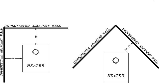
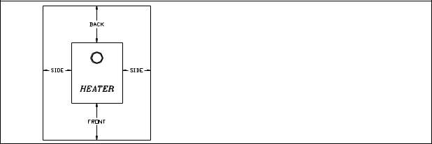
Clearances to any combustibles when measured directly from the floor protector to the ceiling must be a minimum of 84" (2134 mm). Clearances to any combustibles when measured directly from the front of the stove must be a minimum of 48" (1219 mm). The stove must also be placed so as to maintain the minimum clearances to combustible walls specified for each type of connector used. See Table 1.3 below for all clearance measures. Refer to Figure 1.3 for a diagram of each of the measures A through C.
|
|
Single walled connector |
Listed double walled |
|
|
connector |
|
Unit: |
|
|
|
|
|
|
|
To sidewall |
(A) |
18" (406 mm) |
18" (406 mm) |
|
|
|
|
To back wall |
(B) |
18" (406 mm) |
18" (406 mm) |
|
|
|
|
To corner |
(C) |
12" (305 mm) |
12" (305 mm) |
|
|
|
|
|
|
|
|
TABLE 1.3 Clearances to combustible materials
FIGURE 1.3 Clearances to combustible materials
6
1.3.1 Reduced clearances using shielding
You may decrease the minimum clearances to combustible materials by installing heat radiation shields between the walls or the ceiling and the stove. Those heat radiation shields must be installed permanently, and must be made of a heat-resistant or heat-tolerant material.
Note : Walls and ceiling on the vertical and horizontal plan of the pipe connectors must be protected if the clearances of 18’’ are not met.
Consult the table below:
|
Reducing Clearances With |
|
TYPE OF PROTECTION |
Shielding |
|
Sides and |
|
|
|
Top |
|
|
Rear/Back |
|
|
|
|
Sheet metal, a minimum of 0,013" (0,33 mm) spaced out at least 7/8" (21 mm) by non-combustible spacers.
Ceramic tiles, or an equivalent non-combustible material on fire-proof supports spaced out at least 7/8" (21 mm) by noncombustible spacers.
Ceramic tiles, or an equivalent non-combustible material on fire-proof supports with a minimum of 0,013" (0,33 mm) sheet metal backing spaced out at least 7/8" (21 mm) by noncombustible spacers.
67% 50%
50% 33%
67% 50%
Brick spaced out at least 7/8" (21 mm) by non-combustible spacers.
Brick with a minimum of 0,013" (0,33 mm) sheet metal backing spaced out at least 7/8" (21 mm) by noncombustible spacers.
50% N/A
67% N/A
Source: CSA Standard B365-1991, Table 4, Page 27
7
1.4FLOOR PROTECTOR
If the stove is to be installed on top of a combustible floor, it must be guarded by a non-combustible material extending at least 18” (300mm) from the front and 8” (200mm) from the sides and the back of the firebox., as shown in Figure 1.4 below.
Please note that a floor protection is required with the pedestal models for spark and ash shielding, but not for limiting floor temperatures from the radiant heat of the stove. The stove was designed and safety tested so that without any protection, the floor would not overheat.
Please refer to local building codes for suitable floor protection materials.
FRONT |
SIDES |
BACK |
18” (300 mm) |
8” (200 mm) |
8” (200 mm) |
FIGURE 1.4 Floor protector
CAUTION: DO NOT INSTALL IN A BEDROOM.
8

SECTION 2.0 CHIMNEY (FLUE SYSTEM)
2.1DEFINITIONS
For clarity, the following definitions should be used with respect to these instructions:
•A chimney system consists of a connector off the top of the stove, and a chimney, which attaches to the connector and terminates outside the house.
•A chimney can be a masonry chimney (of masonry construction with an inside liner), or a factory built chimney.
•A factory built chimney can be a double walled chimney (two concentric pipes with insulation - sometimes referred to as an insulated solid pack) or an air cooled chimney (three concentric pipes, with insulation between the first and second pipes, and air between the second and third pipes).
•A single walled connector is a single pipe.
•A double walled connector has two concentric pipes, no insulation, and is an air cooled connector.
2.2CHIMNEY
CAUTION:
•DO NOT fill any framed space around the factory-built chimney with insulation or any other material. Insulation placed in this area could cause adjacent combustibles to overheat.
•Do not use makeshift compromises during installation as they may be safety hazards, and a fire could result.
•Do not connect this unit to a chimney system serving another appliance.
•Do not cut rafters or ceiling joists without first consulting a building official to ensure structural integrity is not compromised.
Your wood stove may be hooked up with a factory built or masonry chimney. If you are using a factory built chimney, it must comply with UL103 (USA) or ULCS629 (Canada) standards. It must therefore be a 6” (152mm) HT Type (2100°F) chimney. It is extremely important that it be installed according to the manufacturer's specifications. The manufacturers’ installation instructions and specified clearances should always be followed in accordance with local and national installation codes. In Canada the CSA B365 and the CSA C22.1 installation codes are to be followed. In the USA the ANSI NFPA 70 and ANSI NFPA 211 installation codes are to be followed.
9
If you are using a masonry chimney, it is important that it be built in compliance with the specifications of the Building Code. It must be lined with fire clay bricks, or clay tiles, sealed together with fire cement, or have a listed solid fuel burning stainless steel liner. Round chimneys are the most efficient.
The interior diameter of the chimney should be identical to the stove's smoke exhaust. A chimney which is too small may cause draft problems, since it may not have the required volume to properly evacuate the quantity of smoke resulting from the combustion. A chimney whish is too large may also cause draft problems. In fact, a large chimney will be harder to warm-up and may not reach high enough temperatures to create a proper draft effect. Note that it is the chimney which creates the draft effect, not your stove.
Your stove's performance is therefore directly dependent on an adequate draft from your chimney.
The following recommendations may be useful for the installation of your chimney:
•Do not connect your stove to a chimney serving another appliance.
•The chimney must rise above the roof at least 3' (0.9 mm) from the uppermost point of contact. See Figure 2.2.
•The chimney must exceed any part of the building or other obstruction within a 10' (3.04 m) distance by a height of at least 2' (0.6 m). See Figure 2.2.
•The minimum overall height of the chimney system, measured from the stove top to the exterior termination cap of the chimney should be at least 12' (3.66m). A chimney which is too short may lack the “tunnel effect” required to obtain a proper draft.
•Installation of an interior chimney is always preferable to an exterior chimney. Chimneys constructed outside of the home on an exterior wall should be avoided if possible, especially in colder climates. The gas which circulates into an interior chimney will cool more slowly, thus reducing the build-up of creosote and the risk of flue fires.
•All else being equal, cooler chimneys will have less draft than hotter ones. This problem will be amplified if the chimney is excessively long. A chimney which is excessively long may be very hard to warm-up due to its higher volume. A cool chimney may even down draft (reverse flow) due to the difficulty in heating it up to operating temperature while trying to evacuate the stack gases.
•If an exterior chimney is used, the best results will be obtained by using a connector vertically off the unit to the highest possible point before elbowing off horizontally to the exterior chimney. For efficiency and safety reasons the stove must not be installed with an insulated chimney connected directly to the appliance.
•Using a fire screen at the extremity of the chimney requires regular inspection in order to insure that it is not obstructed, thus blocking the draft. It should be cleaned when necessary.
10
 Loading...