

Drager Medical Air Compressor User manual
Atemluftkompressor
Medical Air Compressor
Compresseur d'air médical
Compresor de aire
Ademhalingsluchtcompressor
Compressore di aria respiratoria
Andningsluftkompressor
Компpессоp для подачи
вдыxаемого воздyxа
Gebrauchsanweisung
Seite 2
Instructions for Use
Page 2
Notice d'utilisation
Page 24
Instrucciones de uso
Página 24
Gebruiksaanwijzing
Pagina 46
Istruzioni per l'uso
Pagina 46
Bruksanvisning
Sida 68
Рyководство по
эксплyатации
Стpаница 68
MT-763-90a

Inhalt
Contents
Inhalt
Seite
Zu Ihrer und Ihrer Patienten Sicherheit......................3
Zweckbestimmung..................................................... 4
Vorbereiten................................................................. 4
Vor der ersten Inbetriebnahme......................................4
Auf das Evita Mobil-Fahrgestell montieren.....................5
Auf den separaten Fahrgestellfuß montieren................. 8
Kompressor anschließen.............................................. 8
Für Standby-Funktion...................................................9
Betrieb........................................................................ 9
Standby-Funktion......................................................... 9
Betriebsende..............................................................10
Pflege........................................................................10
Instandhaltungsintervalle..........................................11
Filtergruppe ausbauen................................................11
Vorfilter wechseln.......................................................12
Hauptfilter wechseln...................................................12
Ansaugfilter wechseln.................................................14
Filtergruppe einbauen.................................................15
Sicherungen wechseln............................................... 15
Contents
Page
For Your Safety and that of your Patients.................. 3
Intended Use.............................................................. 4
Preparing for use........................................................ 4
Before first use.............................................................4
Installing the compressor on the Evita trolley.................5
Installing the compressor on a separate trolley..............8
Connecting the compressor......................................... 8
Standby mode..............................................................9
Operation....................................................................9
Standby mode..............................................................9
Switching off.............................................................. 10
Routine maintenance................................................10
Maintenance intervals............................................... 11
Removing the filter group............................................11
Changing the prefilter.................................................12
Changing the main filter..............................................12
Changing the intake filter............................................ 14
Installing the filter group..............................................15
Replacing the fuses.................................................... 15
Fehler - Ursache - Abhilfe.........................................16
Was ist was............................................................... 18
Technische Daten..................................................... 19
Funktionsbeschreibung............................................ 21
Bestell-Liste.............................................................. 23
Fault - Cause - Remedy.............................................17
What's what...............................................................18
Technical data...........................................................19
Functional description...............................................21
Order list................................................................... 23
2

Zu Ihrer und Ihrer Patienten Sicherheit
For Your Safety and that of your Patients
Zu Ihrer und Ihrer Patienten
Sicherheit
Gebrauchsanweisung beachten
Jede Handhabung an dem Gerät setzt die genaue
Kenntnis und Beachtung dieser Gebrauchsanweisung
voraus. Das Gerät ist nur für die beschriebene
Verwendung bestimmt.
Instandhaltung
Das Gerät muss alle 6000 Betriebsstunden, jedoch
mindestens einmal jährlich, Inspektionen und Wartungen
durch Fachleute unterzogen werden (mit Protokoll).
Instandsetzungen am Gerät nur durch Fachleute. Für den
Abschluss eines Service-Vertrags sowie für Instandsetzungen empfehlen wir den DrägerService.
Bei Instandhaltung nur Original-Dräger-Teile verwenden.
Kapitel "Instandhaltungsintervalle" beachten.
For Your Safety and that of your
Patients
Strictly follow the Instructions for Use
Any use of the apparatus requires full understanding and
strict observation of these instructions. The apparatus
may only be used for the purposes specified here.
Maintenance
The apparatus must be inspected and serviced (and a
record kept) by trained service personnel after every
6000 hours of operation or at least once per year.
Repair and general overhaul of the apparatus may only be
carried out by trained service personnel. We recommend
that a service contract be obtained with DrägerService
and that all repairs also be carried out by them.
Only authentic Dräger spare parts may be used for
maintenance. Observe the chapter "Maintenance
intervals".
Zubehör
Nur das in der Bestell-Liste aufgeführte Zubehör
verwenden.
Kein Betrieb in explosionsgefährdeten Bereichen
Das Gerät ist nicht für den Betrieb in
explosionsgefährdeten Bereichen zugelassen.
Haftung für Funktion bzw. Schäden
Die Haftung für die Funktion des Gerätes geht in jedem
Fall auf den Eigentümer oder Betreiber über, soweit das
Gerät von Personen, die nicht dem DrägerService
angehören, unsachgemäß gewartet oder instandgesetzt
wird oder wenn eine Handhabung erfolgt, die nicht der
bestimmungsgemäßen Verwendung entspricht.
Für Schäden, die durch die Nichtbeachtung der
vorstehenden Hinweise eintreten, haftet Dräger nicht.
Gewährleistungs- und Haftungsbedingungen der
Verkaufs- und Lieferbedingungen von Dräger werden
durch vorstehende Hinweise nicht erweitert.
Accessories
Only the accessories specified in the Order List may be
used with the apparatus.
Not for use in areas of explosion hazard
This apparatus is neither approved nor certified for use in
areas where combustible or explosive gas mixtures are
likely to occur.
Liability for proper function or damage
Liability for the proper function of the apparatus is
irrevocably transferred to the owner or operator to the
extent that the apparatus has been improperly serviced or
repaired by personnel not employed or authorized by
DrägerService or if it has been used in a manner not
conforming to its intended use.
Dräger cannot be held responsible for damage caused
by non-compliance with the recommendations given
above. The warranty and liability provisions of the terms
of sale and delivery of Dräger are likewise not modified
by the recommendations given above.
Dräger Medical AG & Co. KGaA
Dräger Medical AG & Co. KGaA
3

Zweckbestimmung
Vorbereiten
Vor der ersten Inbetriebnahme
Intended Use
Preparing for use
Before first use
Zweckbestimmung
Atemluftkompressor zur Versorgung
eines Beatmungsgerätes mit medizinischer Druckluft.
Nicht in Gegenwart entflammbarer
Gase oder Narkosemittel benutzen, Brandgefahr!
Keine brennbaren Flüssigkeiten in
der Nähe des Kompressors versprühen, Brandgefahr!
Schadstoffe in der Raumluft
vermeiden!
Der Kompressor saugt Raumluft an.
Schadstoffe würden zum Patienten
gelangen.
Für die Versorgung von lebenserhaltenden Beatmungsgeräten:
Wird der Kompressor zur Versorgung von lebenserhaltenden Beatmungsgeräten eingesetzt, so ist für
den Fall eines Defekts am Kompressor eine ausreichende DruckluftErsatz-Versorgung sicherzustellen!
Lebenserhaltende Beatmungsgeräte,
die vom Kompressor versorgt werden, müssen über eine Alarmfunktion
für zu geringen Versorgungsdruck
verfügen!
Intended Use
Air compressor supplying
compressed air for medical
ventilators.
Must not be used in the presence
of flammable gases or
anaesthetics. Fire hazard!
Inflammable liquids must not be
sprayed near the compressor. Fire
hazard!
Prevent pollution of room air!
The compressor draws in air from
the room. Any pollutants in the air
would reach the patient.
For supplying life-supporting
ventilators:
If the compressor is used to supply
air to life-support ventilators, an
adequate alternative supply of
medical air must be ensured in case
a fault develops in the compressor!
Life-support ventilators drawing air
from the compressor must be
equipped with a warning function in
case the supply pressure drops too
low!
Vorbereiten
Vor der ersten Inbetriebnahme
Der Kompressor wird ohne Fahrgestell angeliefert. Er kann auf das
Evita Mobil-Fahrgestell montiert
werden oder auf den separaten
Fahrgestellfuß.
Atemluftkompressor erst nach
der Montage in das Fahrgestell
betreiben.
Sonst kann das Kompressoraggregat mangels Luftzirkulation
beschädigt werden!
Montage nur durch Fachleute.
Benötigte Werkzeuge:
Schlüssel für Innensechskantschraube SW 5,
Kreuzschlitzschraubendreher,
Größe 2,
Gabelschlüssel SW 19.
Preparing for use
Before first use
The compressor is supplied without
trolley. It can be installed on the Evita
trolley or on a separate trolley.
The medical air compressor must
not be started up until it has been
installed on the trolley.
The compressor unit may be
damaged as a result of poor air
circulation if this is not done!
The compressor may only be
installed by trained service
personnel.
Tools required:
Spanner for size 5 Allen screw
Phillips screwdriver, size 2
Size 19 fork wrench
4
Vorbereiten
Auf das Evita Mobil-Fahrgestell montieren
Preparing for use
Installing the compressor on the Evita
trolley
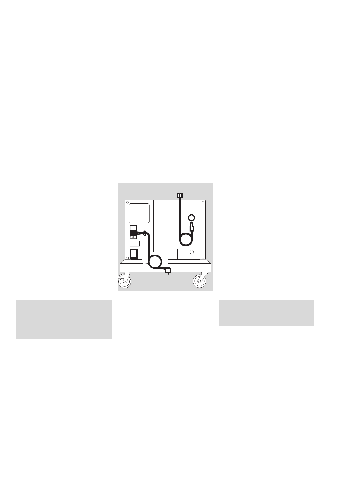
Auf das Evita Mobil-Fahrgestell montieren
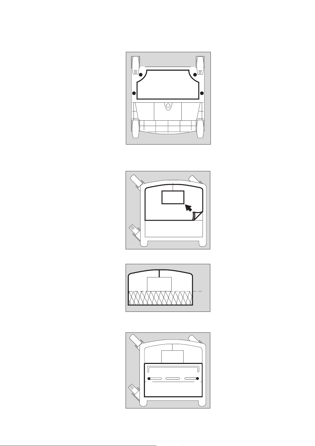
● Beatmungsgerät vom Evita Mobil-
Fahrgestell abnehmen.
● Evita Mobil-Fahrgestell auf den
Boden legen, dass die Unterseite
zugänglich ist.
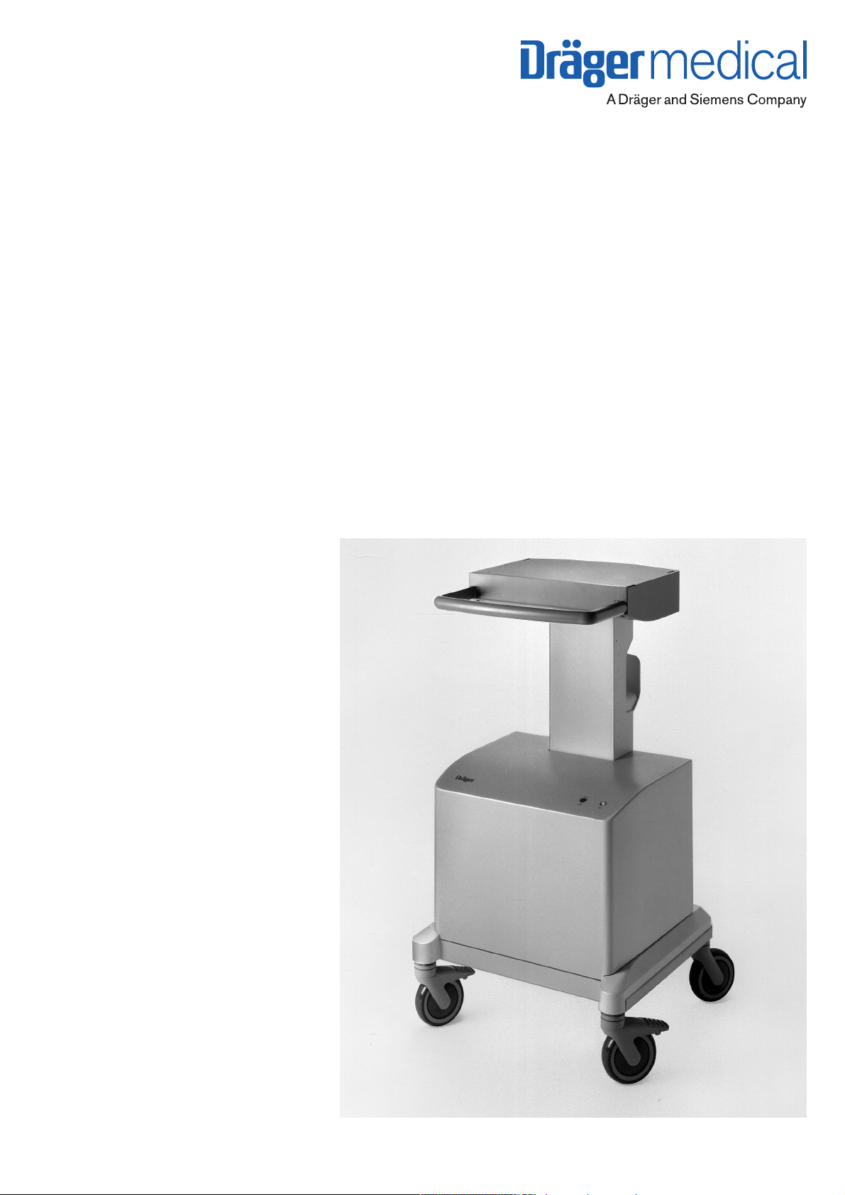
1 Abluftkappe mit beiliegenden
Kreuzschlitzschrauben unter den
Rahmen des Fahrgestells
schrauben.
● Fahrgestell wieder auf die Rollen
stellen.
2 Schaumstoffmatte aus dem Fahr-
gestell herausnehmen.
1
1
1 1
Installing the compressor on
the Evita trolley
● Remove the ventilator from the
Evita trolley.
● Lay the Evita trolley on the ground
so that the underside is
accessible.
1 Secure the exhaust air cover to
the trolley frame with the enclosed
Phillips screws.
● Turn the trolley upright again.
01429080
2 Remove the foam mat from the
trolley.
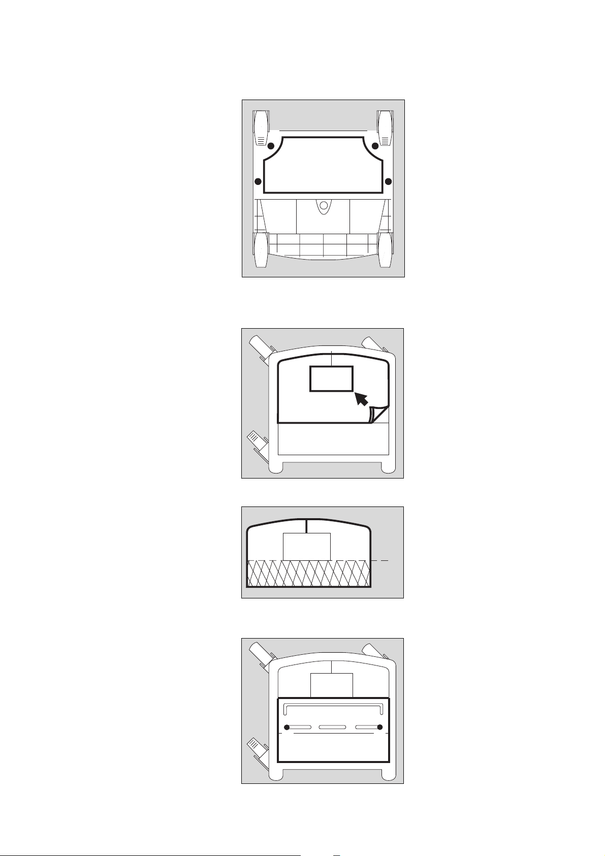
● Schaumstoffmatte an der vorbe-
reiteten Schnittstelle abschneiden.
3 Die beiden Teile wieder in das
Fahrgestell einlegen.
4 Die beiden Schrauben der
Batterieabdeckung herausschrauben, Batterieabdeckung
herausnehmen.
● Die beiden Schrauben unter der
Batterieabdeckung herausschrauben.
3 3
2
01529080
● Cut the foam mat off along the
prepared line.
3 Place both parts in the trolley.
✂
01629080
4 Undo the two screws on the
battery compartment cover and
remove the cover.
● Undo the two screws below the
battery compartment cover.
44
01729080
5
Vorbereiten
Auf das Evita Mobil-Fahrgestell montieren
Preparing for use
Installing the compressor on the Evita
trolley
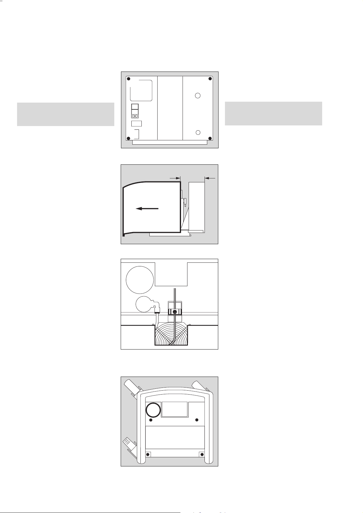
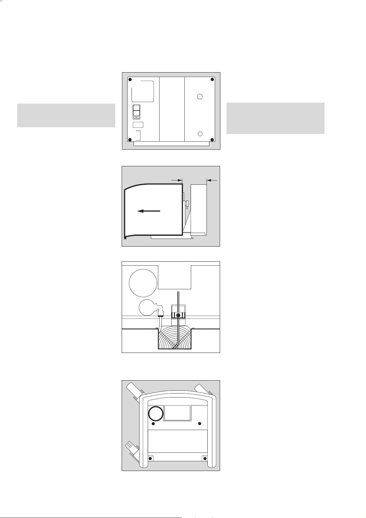
Am Kompressor:
1 Die vier Innensechskant-
schrauben auf der Rückseite
herausschrauben.
Sicherstellen, dass Netzstecker
gezogen, sonst Gefahr eines
elektrischen Schlags!
2 Die Haube vorsichtig nur
ca. 10 cm zurückziehen, dass das
Kabel der Anzeigelampe nicht
abgerissen wird.
On the compressor:
1 Undo the four Allen screws on the
1
1
rear of the compressor.
Ensure that the mains power
cable has been unplugged in
order to avoid electric shocks!
1
1
00129080
2 Carefully draw the shroud back
ca. 10 cm
approx. 10 cm so that the
indicator lead is not pulled off.
2
00229080
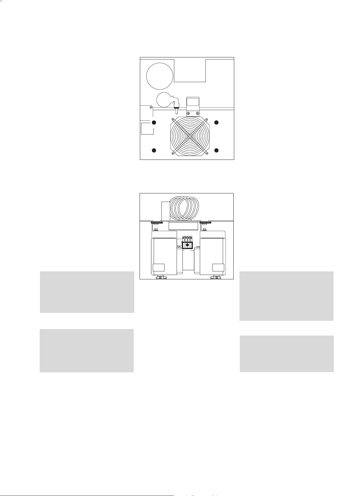
3 Kreuzschlitzschraube am Stecker
herausschrauben, Stecker ziehen,
Haube ganz abziehen.
4 Kompressor auf das Fahrgestell
stellen, Druckbehälter neben der
Säule platziert.
5 Kompressor mit den vier Innen-
sechskantschrauben und Unterlegscheiben am Fahrgestell fest
schrauben.
3 Undo the Phillips screw on the
plug connector, unplug the
connector and remove the shroud
completely.
3
01829080
4 Place the compressor on the
trolley with the pressure vessel
alongside the column.
5 Tightly secure the compressor to
4
55
the trolley with the four Allen
screws and washers.
5
5
00529080
6
Vorbereiten
Auf das Evita Mobil-Fahrgestell montieren
Preparing for use
Installing the compressor on the Evita
trolley
1 Die vier Innensechskantschrau-
ben der Transportsicherung
herausschrauben.
2 Die beiden Laschen der
Transportsicherung herausziehen.
3 Den Motorstecker stecken und
mit der Kreuzschlitzschraube
sichern.
Laschen und Schrauben der
Transportsicherung für spätere
Transporte aufbewahren.
1
1
2 2
3
1 Undo the four Allen screws
securing the internal packing.
1
1
01929080
2 Pull out the two tabs on the
internal packing.
3 Plug in the motor connector and
secure it with the Phillips screw.
Keep the tabs and screws from
the internal packing for future use.
Vor jeder Erstinbetriebnahme
Transportsicherung abnehmen,
sonst entstehen starke Vibrationen
am Atemluftkompressor.
Das Kompressoraggregat kann
beschädigt werden!
Vor jedem Transport, der abweicht
vom betriebsgemäßen Transport
im Fahrgestell:
Transportsicherung einbauen,
sonst können die Gummifüße
beschädigt werden.
● Haube aufsetzen, deren Stecker
stecken und mit der Kreuzschlitzschraube sichern.
● Haube zuschieben und die vier
Innensechskantschrauben auf der
Rückseite hineinschrauben.
02029080
This safety mechanism must
always be removed before using
the compressor for the first time,
otherwise major vibrations may
develop in the compressor.
These may damage the
compressor unit!
The internal packing must be fitted
whenever the compressor is
transported without its trolley,
otherwise the rubber feet may be
damaged.
● Fit the shroud, plug in its
connector and secure it with the
Phillips screw.
● Close the shroud and screw
down the four Allen screws on the
rear of the unit.
7
Vorbereiten
Auf den separaten Fahrgestellfuß
montieren
Kompressor anschließen
Preparing for use
Installing the compressor on a separate
trolley
Connecting the compressor
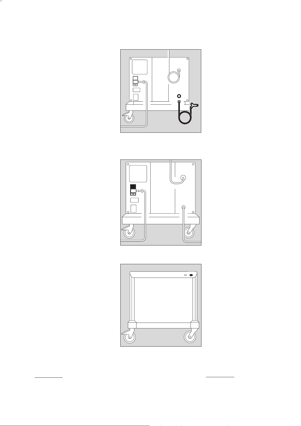
Auf den separaten Fahrgestellfuß montieren
Montage des Kompressors wie für
Evita Mobil-Fahrgestell durchführen.
Kompressor anschließen
1 Sicherstellen, dass die Betriebs-
spannung am Typenschild auf der
Rückseite mit der Netzspannung
übereinstimmt.
2 Schelle abschrauben.
3 Gerätestecker stecken, Kabel
straffen, unter die Schelle klemmen und
2 Schelle festschrauben.
4 Netzstecker in eine geerdete
Steckdose stecken, keinen Adapterstecker benutzen.
5 Druckluft-Anschlussschlauch am
Beatmungsgerät anschrauben.
Installing the compressor on
a seperate trolley
The compressor is installed in the
same way as on the Evita trolley.
Connecting the compressor
5
2
6
3
1
4
1 Check that the operating voltage
specified on the rating plate
matches the mains voltage.
2 Unscrew clamp.
3 Plug in apparatus connector, pull
cable until taut, secure under
clamp and
2 screw clamp back into place.
4 Plug the connector into an
earthed socket; do not use an
adapter.
5 Screw the pressure hose onto the
02129080
ventilator.
Nicht mehrere Beatmungs-
geräte am Kompressor
anschließen!
Der Kompressor kann überlastet
werden.
6 Stecker des Druckluft-Anschluss-
schlauchs fest in die Kupplung
des Kompressors stecken – bis
zum Einrasten.
● Kompressor an möglichst kühlem
Ort platzieren, nicht vor Heizungen oder anderen Wärmequellen.
Für eine ungehinderte Luftzirkulation um den Kompressor herum
sorgen.
● Kompressor nicht in salzhaltiger
Luft betreiben, die Rückschlagventile im Kompressor können
korrodieren.
8
Do not connect more than one
ventilator to the compressor!
It could overload the compressor.
6 Firmly insert the connector on the
pressure hose into the coupling
on the compressor - until it
engages.
● Place the compressor in a cool
place, away from radiators and
other sources of heat.
Ensure that air can circulate freely
around the compressor.
● The compressor must not be
operated in salty air, as this may
cause the non-return valves in the
compressor to corrode.
Vorbereiten
Betrieb
Standby-Funktion
Preparing for use
Operation
Standby mode
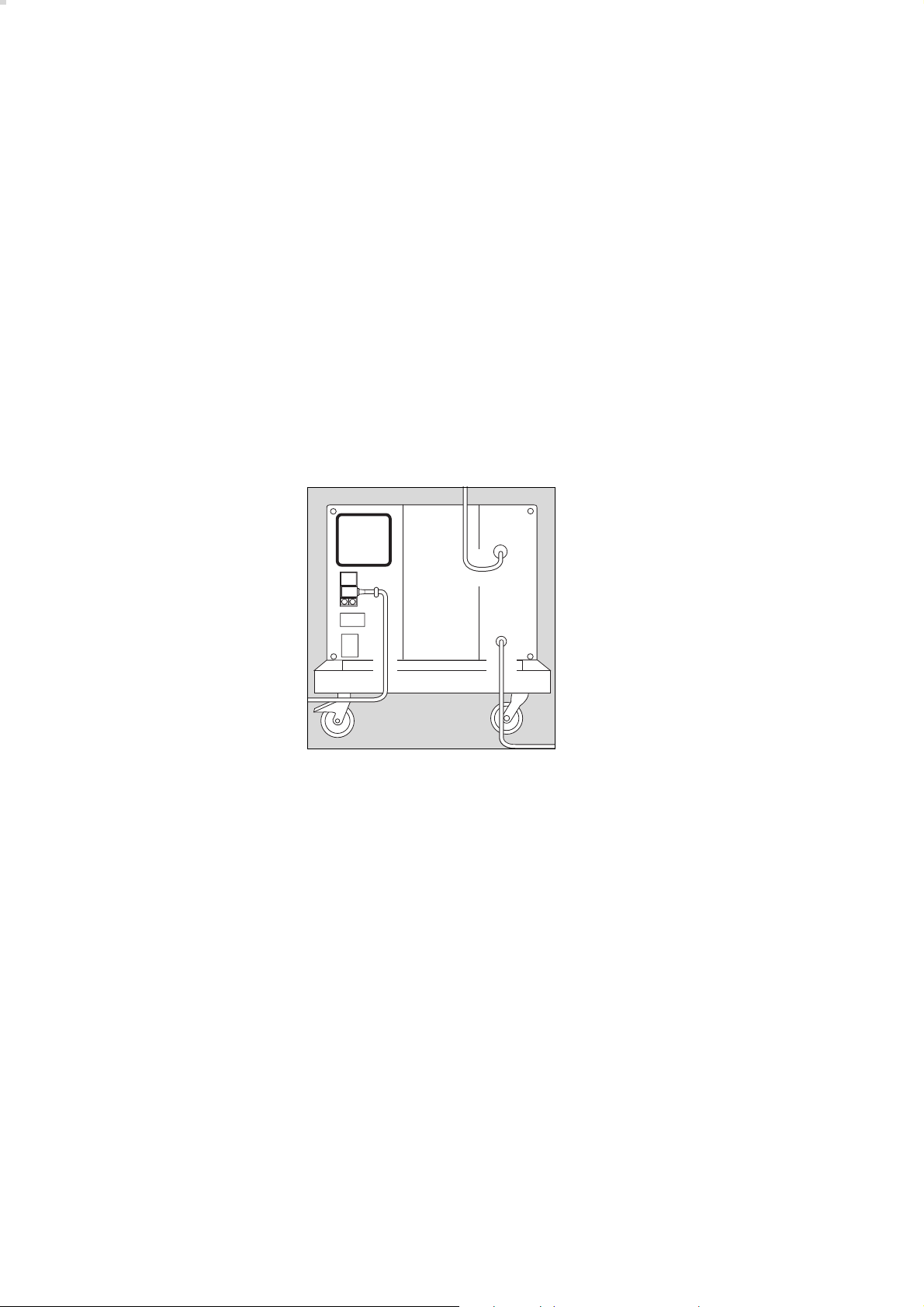
Für Standby-Funktion
(Option)
Zur Versorgung des Beatmungsgerätes bei Ausfall des zentralen
Druckluftsystems
1 Druckluft-Anschlussschlauch am
Kompressor anschrauben.
2 Stecker in die Wandentnahme-
stelle des zentralen Druckluftsystems stecken.
Betrieb
Wurde der Kompressor bei Temperaturen unter 3 °C gelagert:
● Ca. 2 Stunden für Temperatur-
ausgleich abwarten.
3 Netzschalter auf der Rückseite
drücken,
4 die grüne Lampe » NN
Haube leuchtet = EIN.
● Das angeschlossene Beatmungs-
gerät einschalten.
Bei Betriebstörungen siehe "FehlerUrsache-Abhilfe", Seite 16.
NN
« vorn in der
Standby mode
(optional)
For emergency supply if the central
medical air system fails.
1 Screw the pressure hose to the
compressor.
1
2
2 Plug the connector into the wall
socket of the central medical air
system.
02229080
Operation
If the compressor has been stored at
temperatures below 3 °C:
● Wait approx. 2 hours for the
3
compressor to warm up.
3 Press main switch on rear,
4 the green LED » NN
NN
« in the front
of the shroud lights up = ON.
● Now switch on the ventilator.
Refer to "Fault - Cause - Remedy" on
page 17 if any faults develop.
02329080
Standby-Funktion
Zur Versorgung des Beatmungsgerätes bei Ausfall des zentralen
Druckluftsystems
● Netzschalter immer eingeschaltet
lassen = grüne Lampe » NN
in der Haube leuchtet
Der eingeschaltete Kompressor
überwacht den Druck im zentralen
Druckluftsystem:
Fällt der Druck unter 2,7-0,3 bar1),
übernimmt der Kompressor automatisch die Druckluftversorgung des angeschlossenen Beatmungsgerätes.
Steigt der Druck im zentralen Druckluftsystem wieder über 3,4 bar2),
schaltet der Kompressor seine Versorgung ab und bleibt in Standby.
1)
US-Kompressor 115 V/60 Hz/Standby:
2,7±0,2 bar
2)
US-Kompressor 115 V/60 Hz/Standby:
3,2±0,2 bar
NN
« vorn
Standby mode
For emergency supply if the central
4
medical air system fails.
● Always leave the main switch ON
= green LED » NN
NN
« on front of
shroud lights up.
The pressure in the central medical
air system is monitored by the
compressor while switched on:
If the pressure drops below
2.7-0.3 bar1), the compressor
automatically supplies medical air to
the ventilator to which it is
01029080
connected. The compressor
switches off the supply and remains
on standby when the pressure in the
central medical air system rises
above 3.4 bar2).
1)
US Compressor 115 V/60 Hz/Standby:
2.7±0.2 bar
2)
US Compressor 115 V/60 Hz/Standby:
3.2±0.2 bar
9
Betriebsende
Pflege
Switching off
Routine maintenance
Betriebsende
Nach dem Abschalten des Beatmungsgerätes:
● Netzschalter auf der Rückseite
drücken,
● die grüne Lampe » NN
NN
« erlischt
= AUS.
Der Kompressor entlüftet sich
automatisch.
Pflege
Wenn die Filtermatte verschmutzt ist:
1 Filtermatte herausnehmen,
Schmutz ausklopfen, Filtermatte
wieder einsetzen.
● Schmutz am Gehäuse des Kom-
pressors mit einem Einwegtuch
entfernen.
Switching off
After switching off the ventilator:
● Press the main switch on the rear,
● the green LED » NN
NN
« goes out
= OFF.
The compressor is vented
automatically.
Routine maintenance
If the filter mat is soiled:
1 Remove the filter mat, knock out
1
any dirt and insert the mat again.
● Any dirt on the compressor
housing should be wiped off with
a disposable cloth.
Wischdesinfizieren des Gehäuses
Zur Desinfektion Präparate aus der
Gruppe der Flächendesinfektionsmittel verwenden. Aus Gründen der Materialverträglichkeit eignen sich Präparate auf der Wirkstoffbasis von:
– Aldehyden,
– quaternären Ammoniumverbin-
dungen
Wegen möglicher Schädigung der
Materialien eignen sich keine Präpa-
rate auf der Basis von:
– Phenol-haltigen Verbindungen,
– Halogen-abspaltenden Verbin-
dungen,
– starken organischen Säuren,
– Sauerstoff-abspaltenden
Verbindungen.
● wischdesinfizieren
z.B. mit Incidur (Fa. Ecolab
Deutschland GmbH)
● Anwendungsvorschriften des
Herstellers beachten.
Wiping with disinfectant
02429080
A surface disinfectant can be used
to wipe the housing. Preparations
based on:
– aldehydes or
– quaternary ammonium
compounds
Preparations based on the following
compounds should not be used as
they may damage the housing:
– Compounds containing phenol
– Compounds giving off halogens
– Strong organic acids
– Compounds giving off oxygen.
● Wipe with disinfectant
e.g. Incidur (Ecolab
Deutschland GmbH)
● Note the manufacturer's
instructions.
10
Instandhaltungsintervalle
Filtergruppe ausbauen
Maintenance intervals
Removing the filter group
Instandhaltungsintervalle
Instandhaltung durch Fachleute
spätestens alle
6000 Betriebsstunden: Filterwechsel für
(siehe Betriebs- Vorfilter,
stundenzähler) Hauptfilter,
Ansaugfilter
Im Bedarfsfall Instandhaltung in
kürzeren Intervallen durchführen.
War das Gerät keine 6000 Stunden
in Betrieb:
● Nach spätestens einem Jahr
Inspektion und Wartung
durchführen.
● Verschmutzte Filter mit dem
Hausmüll entsorgen.
Netzstecker ziehen! Sonst Gefahr
eines elektrischen Schlags!
Maintenance intervals
Maintenance work may only be
carried out specially trained service
personnel.
at least every
6000 hours: Change filters
(see operating in prefilter,
hours counter): main filter and
intake filter
Carry out maintenance more
frequently if necessary.
If the apparatus has not been in
operation for 6000 hours:
● Carry out inspection and servicing
after not more than a year.
● Dispose of used filters with
domestic waste.
The apparatus must always be
unplugged from the mains in
order to avoid electric shocks!
1
1
Filtergruppe ausbauen
Gehäuse abnehmen, siehe Seite 6.
1 Beide Kreuzschlitzschrauben
herausschrauben.
2 Schläuche abnehmen:
Ring zurückgedrückt halten und
gleichzeitig Schlauch aus dem
Anschluss ziehen.
● Filtergruppe herausnehmen.
Removing the filter group
Remove the housing, see page 6.
1 Undo both Phillips screws.
03029080
2 Disconnect the hoses:
Pull back and hold the ring while
pulling the hose from the socket
at the same time.
● Remove the filter group.
2
2
2
02829080
11
Instandhaltungsintervalle
Vorfilter wechseln
Hauptfilter wechseln
Maintenance intervals
Changing the prefilter
Changing the main filter
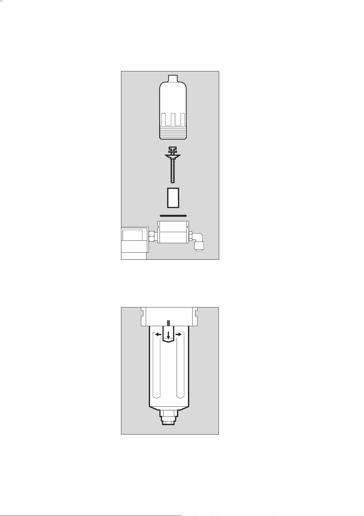
Vorfilter wechseln
1 Gehäuse mit der Hand
abschrauben.
2 Kreuzschlitz-Schraube abschrau-
ben und mit Kunststoffscheibe
abnehmen.
3 Filterhülse herausnehmen und
gegen eine Neue wechseln.
3 Neue Filterhülse einsetzen.
2 Mit Kreuzschlitz-Schraube und
Kunststoffscheibe festschrauben.
4 Alten O-Ring herausnehmen,
neuen O-Ring einlegen.
Changing the prefilter
1 Unscrew the housing by hand.
2 Unscrew recessed head screw
and remove screw and plastic
washer.
1
3 Remove the filter sleeve and
replace.
3 Insert the new filter sleeve.
2 Fasten in place with recessed
head screw and plastic washer.
2
4 Remove old O-ring and fit new
O-ring.
3
4
● Gehäuse fest mit der Hand
anschrauben.
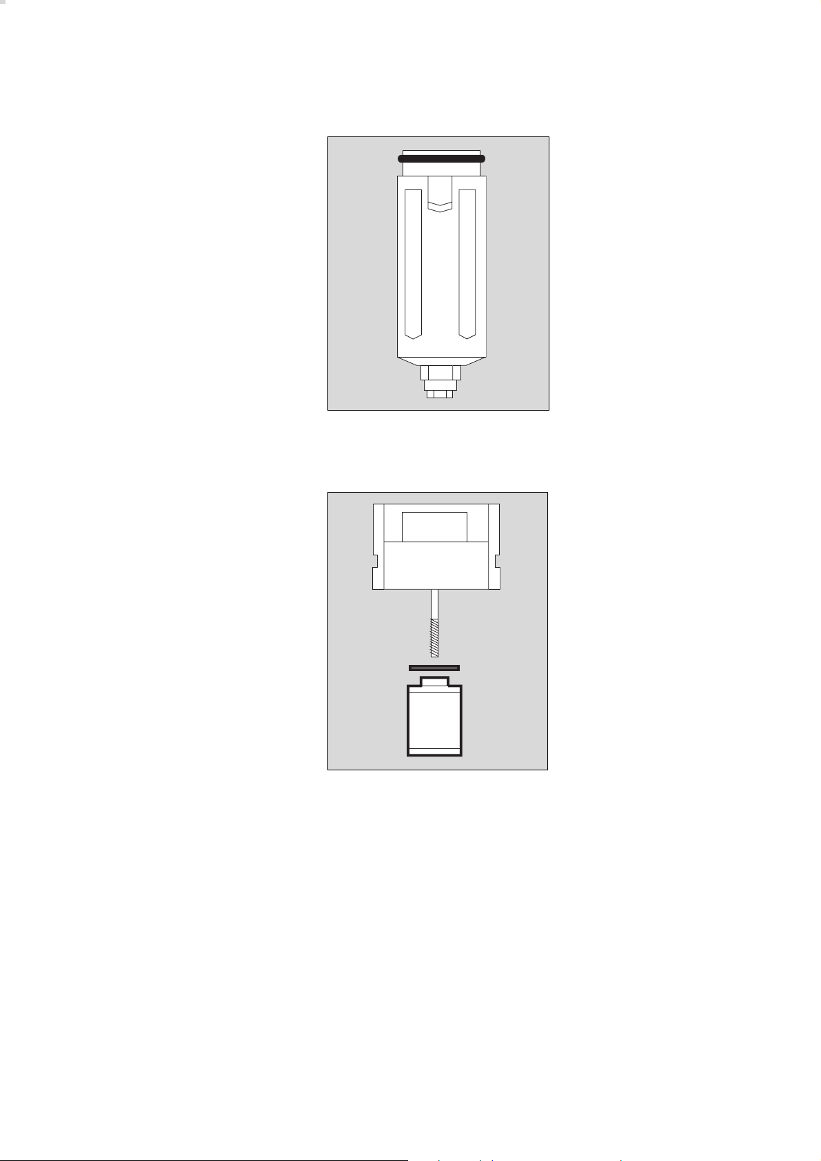
Hauptfilter wechseln
5 Klinke gezogen halten und gleich-
zeitig
6 Gehäuse drehen, bis sich die
Markierungen ( II ) decken.
● Gehäuse abziehen.
● Screw housing together by hand.
03129080
Changing the main filter
5 Pull and hold the catch while
simultaneously
66
5
6 turning the housing until the marks
( II ) line up.
● Remove the housing.
12
02629080
Instandhaltungsintervalle
Hauptfilter wechseln
Maintenance intervals
Changing the main filter
1 Alten O-Ring vom Gehäuse
abnehmen, neuen O-Ring
montieren.
2 Alte Filterhülse mit der Hand
herausschrauben und neue Filterhülse einschrauben.
● Gehäuse so einsetzen, dass sich
die Markierungen decken und
drehen bis die Klinke hörbar
einrastet.
● Mit leichtem Zug am Gehäuse
prüfen, ob das Gehäuse eingerastet ist.
1 Remove old O-ring from housing
1
and fit new O-ring.
03729080
2 Unscrew old filter sleeve by hand
and screw in new filter sleeve.
● Insert the housing so that the
marks line up, then turn until the
catch is heard to engage.
● Lightly pull the housing to ensure
that it has engaged.
2
02729080
13
Instandhaltungsintervalle
Ansaugfilter wechseln
Maintenance intervals
Changing the intake filter
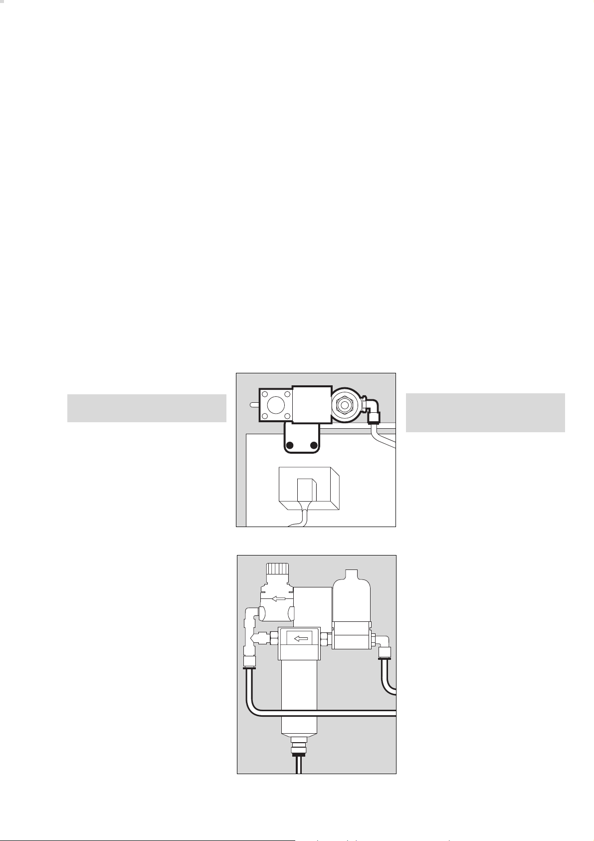
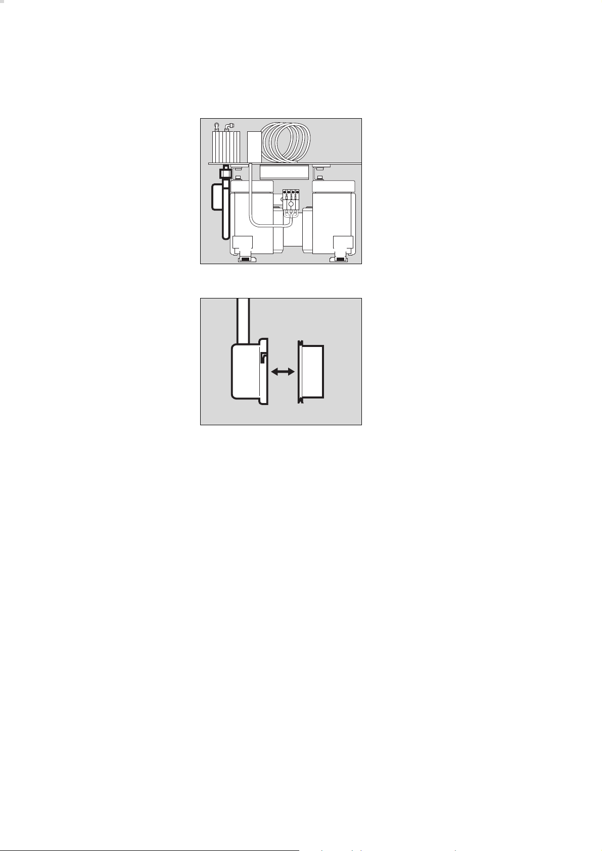
Ansaugfilter wechseln
1 Die jeweils zwei Innensechskant-
schrauben an den vorderen und
hinteren Montageblechen des
Kompressoraggregats herausschrauben.
2 Druckluftschlauch mit Gabel-
schlüssel SW 19 abschrauben,
mit einem zweiten Maulschlüssel
das Verbindungsstück zum
Wärmetauscher vor Losdrehen
sichern.
● Das Kompressoraggregat soweit
herausziehen, bis das rückseitige
Ausgangsrohr des Filtergehäuses
nicht mehr aus der Bohrung ragt.
3 Filtergehäuse im Uhrzeigersinn
drehen und abnehmen.
4 Altes Ansaugfilter herausnehmen
und ein Neues ins Filtergehäuse
einsetzen.
● Filtergehäuse aufsetzen, das Rohr
nach hinten zeigend ca. auf Position "11 Uhr".
3 Filtergehäuse gegen Uhrzeiger-
sinn drehen, bis es verriegelt ist.
Rohr ist in horizontaler Position.
● Durch Ziehen den festen Sitz des
Filtergehäuses prüfen.
● Kompressoraggregat zurück-
schieben, dabei das Rohr in die
Bohrung einführen.
2 Druckluftschlauch mit Gabel-
schlüssel SW 19 festschrauben,
mit einem zweiten Maulschlüssel
das Verbindungsstück zum
Wärmetauscher vor Losdrehen
sichern.
1 Kompressoraggregat vorn und
hinten mit jeweils zwei Innensechskantschrauben festschrauben.
Changing the intake filter
1 Remove the two Allen screws on
the front of the assembly plates of
the compressor unit and undo the
two rear Allen screws two turns.
2
3
1
1
4
2 Unscrew the pressure hose with a
size 19 fork wrench and hold the
connector to the heat exchanger
with a second spanner to prevent
it working loose.
● Pull the compressor unit out until
the outlet pipe at the rear of the
filter housing no longer protrudes
03329080
from the hole.
3 Turn the filter housing clockwise
and remove it.
4 Remove the old intake filter and
insert a new filter in the filter
housing.
● Position the filter housing with the
pipe facing to the rear in a
position corresponding roughly to
"11 o'clock".
3 Turn the filter housing
anticlockwise until locked. The
03229080
pipe is now horizontal.
● Pull gently to check that the filter
housing is secure.
● Push the compressor unit back,
guiding the pipe into the hole at
the same time.
2 Secure the pressure hose with a
size 19 fork wrench and hold the
connector to the heat exchanger
with a second spanner to prevent
it working loose.
1 Secure the compressor unit with
the front and rear Allen screws.
14
Instandhaltungsintervalle
Filtergruppe einbauen
Sicherungen wechseln
Maintenance intervals
Installing the filter group
Replacing fuses
Filtergruppe einbauen
● Schläuche an der Filtergruppe
anschließen, s. Seite 11.
● Filtergruppe festschrauben,
s. Seite 11.
● Haube aufsetzen, deren elektri-
schen Stecker stecken und mit
der Kreuzschlitzschraube sichern.
● Haube zuschieben und die vier
Innensechskantschrauben auf der
Rückseite hereinschrauben.
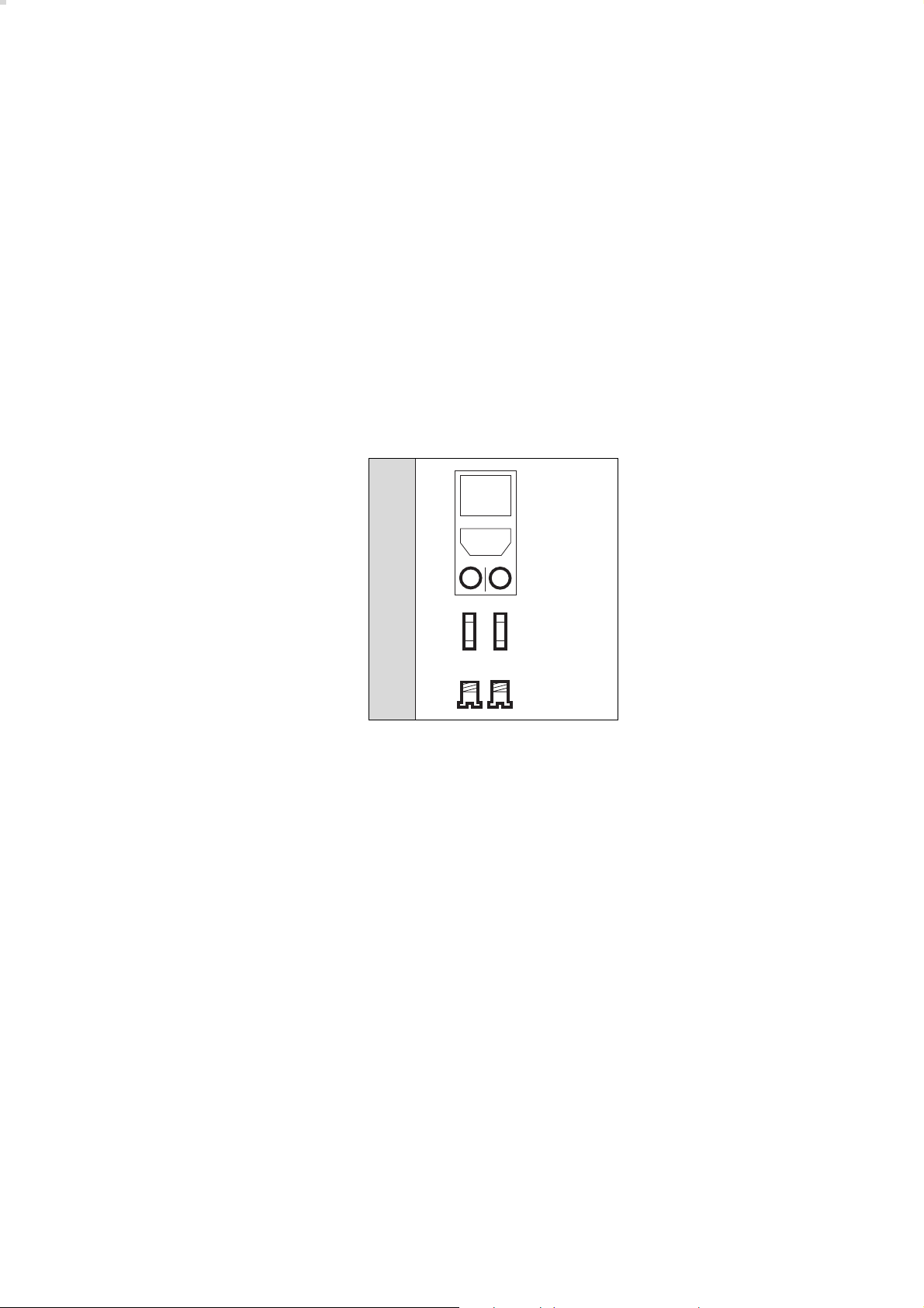
Sicherungen wechseln
● Netzstecker ziehen.
1 Kappen mit Schraubendreher
gegen den Uhrzeigersinn drehen
und herausnehmen.
2 Durchgebrannte Sicherungen aus
den Kappen ziehen und neue
Sicherungen in die Kappen
stecken – Nur die vorgeschriebenen Sicherungen verwenden,
siehe "Technische Daten",
Seite 19.
1 Kappen mit den neuen Sicherun-
gen wieder hereindrehen.
Installing the filter group
● Connect the hoses to the filter
group, see page 11.
● Screw the filter group into place,
see page 11.
● Fit the shroud, plug in its
connector and secure it with the
Phillips screw.
● Close the shroud and screw
down the four Allen screws on the
rear of the unit.
Replacing the fuses
● Unplug the mains connector.
1 Turn the caps anticlockwise with a
screwdriver and remove them.
2 Remove blown fuses from their
caps and insert new fuses. Only
the specified fuses may be used,
see "Technical data" on page 19.
1 Screw the caps with the new
fuses back into place.
2
1
03529080
Gerät entsorgen
– am Ende der Nutzungsphase.
● Gerät nach Rücksprache mit den
zuständigen Entsorgungsunternehmen der fachgerechten
Entsorgung zuführen. Die
geltenden gesetzlichen
Vorschriften beachten!
Disposal of the device
– at the end of its useful life
● After contacting the competent
specialised waste disposal
companies, send the device to the
appropriate expert disposal
facility. Observe all applicable
legal requirements.
15

Fehler - Ursache - Abhilfe
Fehler - Ursache - Abhilfe
Fehler Ursache Abhilfe
Kompressor
vibriert stark
Kompressor läuft,
erzeugt jedoch keinen
oder einen zu geringen
Druck
rote Lampe »Temp [[[[«
leuchtet, begleitet von
einem schnarrenden
Alarmton
Transportsicherung
wurde nicht ausgebaut
Gummifüße am
Kompressoraggregat
Transportsicherung
ausbauen, Seite 7
DrägerService in
Anspruch nehmen
defekt
Ansaugfilter
verschmutzt
Undichtheiten an den
Komponenten des
Ansaugfilter wechseln,
Seite 13
DrägerService in
Anspruch nehmen
Atemluftkompressors
hohe Umgebungstemperatur
Kompressor an kühlem
Ort platzieren, für eine
ungehinderte Luftzirkulation sorgen
Filtermatte verschmutzt Schmutz aus Filter-
matte ausklopfen
oder neue Filtermatte
einsetzen
Lüfter defekt DrägerService in
Anspruch nehmen
Kompressor läuft
nicht an
Für Standby-Geräte:
Kompressor läuft an,
obwohl der Druck in der
zentralen Versorgung
mehr als 2,7-0,3 bar
1)
beträgt.
keine Netzspannung
Netzspannung prüfen
oder
zu niedrige Netzspannung
Sicherungen defekt Sicherungen austau-
schen, Seite 15
Gerät defekt DrägerService in
Anspruch nehmen
Druckschalter defekt
DrägerService in
Anspruch nehmen
1)
US-Kompressor 115 V/60 Hz/Standby:
2,7±0,2 bar
16

Fault - Cause - Remedy
Fault Cause Remedy
Fault - Cause - Remedy
Compressor vibrates
strongly
Compressor runs, but
builds up too little or no
pressure
Red LED »Temp [[[[«
lights up and an alarm
sounds
Compressor refuses to
start
Internal packing has
not been removed
Rubber feet on
Remove internal
packing, page 7
Call DrägerService
compressor unit
defective
Intake filter soiled Replace intake filter,
page 13
Leaks in the
Call DrägerService
compressor
components
High ambient
temperature
Place the compressor
in a cool place and
ensure free air
circulation
Filter mat soiled Knock dirt out of filter
mat or fit a new filter
mat
Fan defective Call DrägerService
Mains voltage too low
Check mains voltage
or
not available
Standby apparatus:
Compressor starts up
although pressure in
central medical air
supply is over
2.7-0.3 bar
1)
Fuses defective Replace fuses, page 15
Apparatus defective Call DrägerService
Pressure switch
Call DrägerService
defective
1)
US Compressor 115 V/60 Hz/Standby:
2.7±0.2 bar
17
Was ist was
What's what
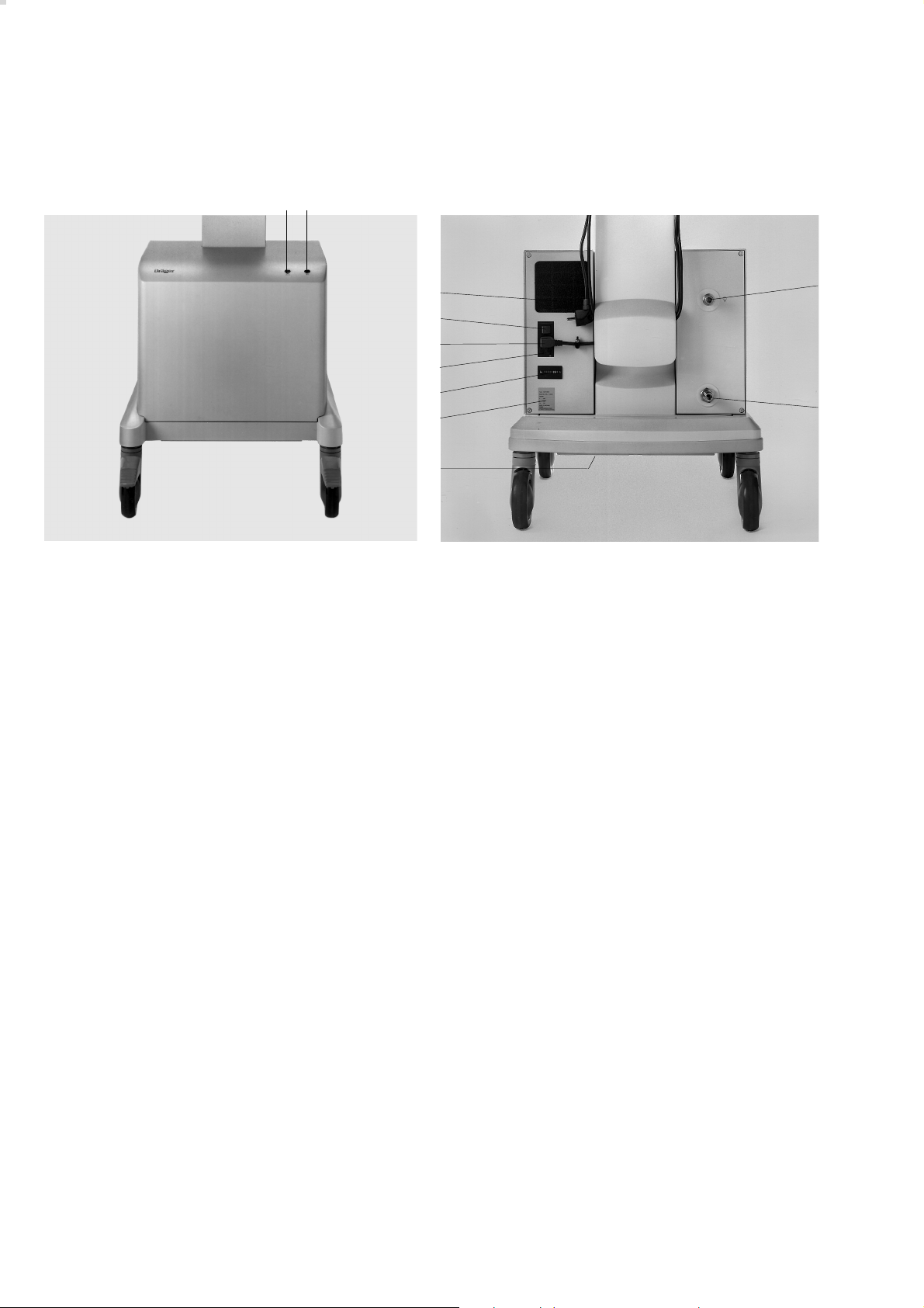
Was ist was
12
1 Rote Lampe »Temp [[[[« für Übertemperatur
2 Grüne Lampe » NN
3 Filtermatte
4 Netzschalter
5 Netzkabel
6 Sicherungen
7 Betriebsstundenzähler
8 Typenschild
9 Abluftkanal
10 Anschluss für Druckluft-Anschlussschlauch
der zentralen Druckluftversorgung
(nur bei Standby-Geräten)
11 Kupplung für Druckluft-Anschlussschlauch
des Beatmungsgerätes
NN
« für Betrieb/ Bereitschaft
What's what
3
4
5
6
7
8
9
MT-780-97
1 Red LED »Temp [[[[« when temperature is too high
2 Green LED » NN
3 Filter mat
4 Main switch
5 Power cable
6 Fuses
7 Operating hours counter
8 Rating plate
9 Exhaust air duct
10 Connection for pressure hose from central medical
air supply (standby apparatus only)
11 Coupling for pressure hose from ventilator
NN
« indicates power on / standby
11
10
MT-781-97
18

Technische Daten
Technical Data
Technische Daten
Umgebungsbedingungen
Betrieb:
Temperatur 10 bis 40 °C
rel. Luftfeuchte 30 bis 95 %
Höhe über dem
Meeresspiegel 0 bis 4000 m
Lagerung:
Temperatur –20 °C bis 70 °C
rel. Luftfeuchte 0 bis 99 %
Höhe über dem
Meeresspiegel 0 bis 16000 m
Leistungskennwerte
Betriebsdruck 4+0,5 bar
Dauerflow minimal 30 L/min bei 3,0 bar
Spitzenflow 180 L/min für max. 0,8 Sekun-
den bei insgesamt
max. 30 L/min
Taupunktreduzierung 5 °C unter Umgebungstempe-
bei Betriebsdruck ratur bei ≥30 L/min und max.
Umgebungstemperatur 40 °C.
15 °C unter Umgebungstemperatur bei 15 L/min und
max. Umgebungstemperatur 40 °C
Luftqualität Staub- und ölfreie Druckluft
Filter ≤1 µm
Druckluftausgang Verschlusskupplung
Alarm Übertemperaturalarm,
optisch (rote Lampe) und
akustisch (Summer mit
Dauerton)
Technical Data
Ambient conditions
Operation:
Temperature 10 to 40 °C
Relative humidity 30 to 95 %
Height above sea level 0 to 4000 m
Storage:
Temperature –20 to 70 °C
Relative humidity 0 to 99 %
Height above sea level 0 to 16,000 m
Performance characteristics
Operating pressure 4+0.5 bar
Continuous flow Minimum 30 L/min at 3.0 bar
Peak flow 180 L/min for max.
0.8 seconds at a total of
max. 30 L/min
Dew point depression 5 °C below ambient
under operating temperature at ≥30 L/min
pressure and max. ambient
temperature 40 °C.
15 °C below ambient
temperature at 15 L/min and
max. ambient
temperature 40 °C
Air quality Dust-free and oil-free
compressed air
Filter ≤1 micron
Compressed air outlet Coupling with check valve
Alarm High temperature alarm, visual
(red LED) and acoustic
(continuous buzzer)
Standby - Drucküberwachung
Kompressor - Druckluftversorgung EIN <2,7-0,3 bar
Kompressor - Druckluftversorgung AUS >3,4 bar
2)
US-Kompressor 115 V/60 Hz/Standby:
1)
Druckluftversorgung
EIN <2,7±0,2 bar
2)
Druckluftversorgung
AUS >3,2±0,2 bar
Standby - pressure monitoring
1)
Compressor medical air ON <2.7-0.3 bar
Compressor medical air OFF >3.4 bar
2)
1)
US Compressor 115 V/60 Hz/Standby:
1)
medical air
ON <2.7±0.2 bar
2)
medical air
OFF >3.2±0.2 bar
19

Technische Daten
Technical Data
Betriebskennwerte
Anschluss für zentrales NIST1)-Anschluss
Druckluftsystem oder DISS2) -Anschluss
elektr. Netzanschluss Stromaufnahme Sicherungen
230 V 50/60 Hz 2,2 ... 2,4 A T4A
andere Varianten
100/ 110/ 115/ 127 V
50/60 Hz 4,2 ... 5,9 A T8A
Elektromagnetische geprüft nach
Verträglichkeit EMV EN 60601-1-2
Schalldruckpegel 50 Hz-Geräte typ. 46 - 49 dB (A)
Schalldruckpegel 60 Hz-Geräte typ. 49 - 52 dB (A)
Operating characteristics
Connection for central NIST1) or DISS2)
medical air system connection
Mains connection Current Fuses
consumption
230 V 50/60 Hz 2.2 ... 2.4 A 4 A slow-blow
Other versions
100/ 110/ 115/ 127 V
50/60 Hz 4.2 ... 5.9 A 8 A slow-blow
Electromagnetic Tested to
compatibility EMC EN 60601-1-2
Sound pressure level 50 Hz-Systems:
Typically 46 - 49 dB (A)
Sound pressure level 60 Hz-Systems:
Typically 49 - 52 dB (A)
Gewicht ca. 45 kg
Abmessungen
(B x H x T) 50 x 38 x 41 cm
Klassifizierung II a
gemäß Richtlinie 93/42/EWG
Anhang IX
UMDNS-Code 10-972
Universal Medical Device
Nomenclature System –
Nomenklatur für Medizingeräte
Weight Approx. 45 kg
Dimensions
(W x H x D) 50 x 38 x 41 cm
Classification II a
as per EC Directive 93/42/EEC
Annex IX
UMDNS-Code 10-972
Universal Medical Device
Nomenclature System –
Nomenclature for medical products
1)
NIST = Non Interchangeable Screw Thread
(unvertauschbarer Anschluss)
2)
DISS = Diameter Indexed Safety System
(unvertauschbarer Anschluss)
20
1)
NIST = Non Interchangeable Screw Thread
2)
DISS = Diameter Indexed Safety System
Funktionsbeschreibung
Functional description
Funktionsbeschreibung
2
1
15
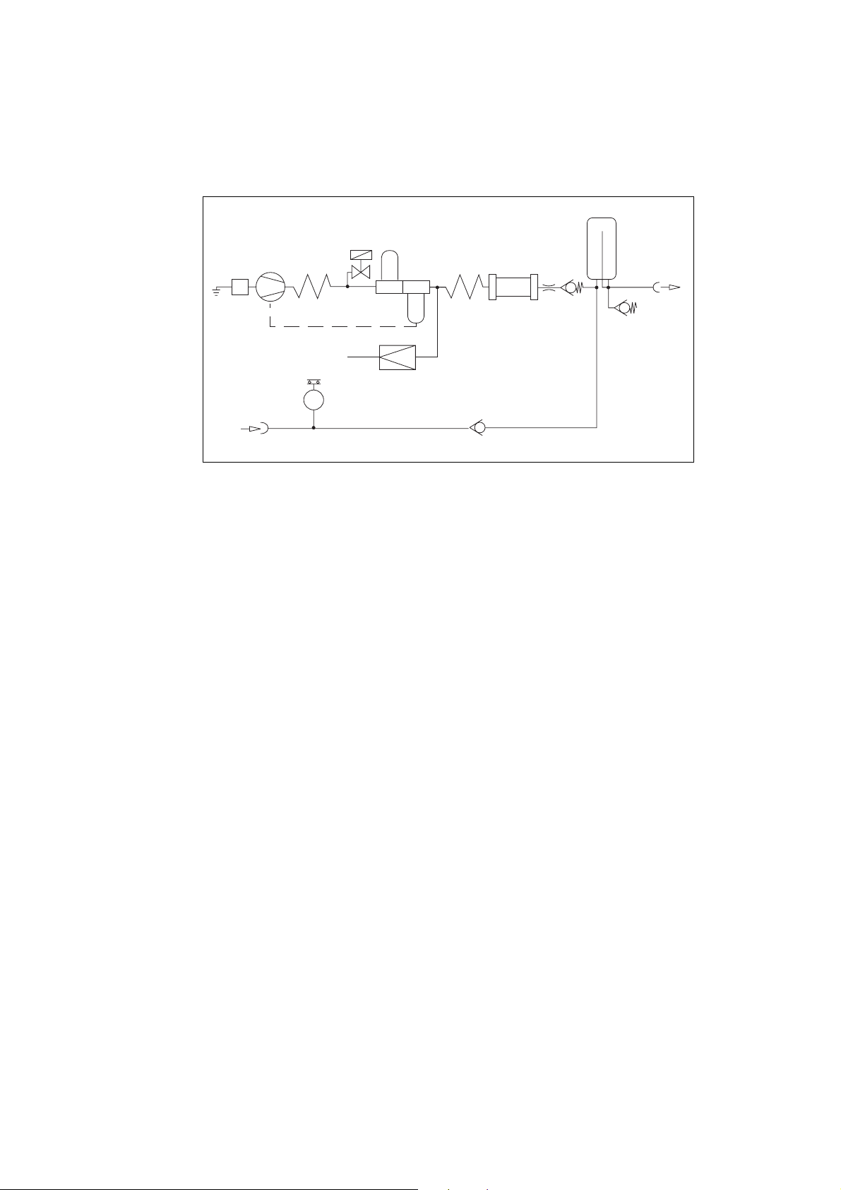
1 Ansaugfilter
2 Kompressoraggregat
3 Kühlspirale
4 Magnetventil
5 Vorfilter
6 Kondensatabscheider
7 Wärmetauscher
8 Druckbegrenzer
9 Membrantrockner
10 Drosseldüse
11 Rückschlagventil
12 Druckbehälter
13 Druckluftausgang
14 Sicherheitsventil
15 Eingang für Standby-Funktion
16 Druckschalter
17 Rückschlagventil
Functional description
12
4
5
3
16
6
8
7
1 Intake filter
2 Compressor unit
3 Cooling coil
4 Solenoid valve
5 Prefilter
6 Condensate trap
7 Heat exchanger
8 Pressure limiter
9 Diaphragm drier
10 Restrictor nozzle
11 Non-return valve
12 Pressure vessel
13 Medical air outlet
14 Relief valve
15 Input for standby mode
16 Pressure switch
17 Non-return valve
17
9
10
11
13
14
Umgebungsluft wird über das Ansaugfilter 1 angesaugt,
im Kompressoraggregat 2 verdichtet und in der Kühlspirale 3 gekühlt. Das Magnetventil 4 öffnet das System
kurzzeitig beim Start des Kompressors.
Die verdichtete Luft wird im Vorfilter 5 gereinigt, Kondensat wird im Kondensatabscheider 6 separiert und abgeführt.
Die so behandelte Luft wird im Wärmetauscher 7 wieder
erwärmt, um einen weiteren Kondensatausfall vor dem
Membrantrockner 9 zu vermeiden.
Im nachgeschalteten Membrantrockner 9 wird die Luft
auf einen Taupunkt von mindestens 5 °C unter Umgebungstemperatur entfeuchtet.
Ambient air is drawn in via the intake filter 1, compressed
in the compressor unit 2 and cooled in the cooling coil 3.
The system is briefly opened by solenoid valve 4 when
the compressor starts up.
The compressed air is cleaned by prefilter 5. Condensate
is collected and removed in the condensate trap 6.
The purified air is re-heated by the heat exchanger 7 in
order to prevent further condensation forming before it
reaches the diaphragm drier 9.
In the diaphragm drier 9, the air is dehumidified to a dew
point at least 5 °C below the ambient temperature.
21

Funktionsbeschreibung
Functional Description
Die entfeuchtete Luft gelangt über Drosseldüse 10 und
Rückschlagventil 11 in den Druckbehälter 12, wo sie
über die Kupplung 14 entnommen wird.
In Standby-Funktion wird das Beatmungsgerät aus der
zentralen Druckluftversorgung über die Kupplung 15,
Rückschlagventil 17 und selbstschließende Kupplung 13
versorgt. Das Kompressoraggregat 2 ist in Standby.
Wenn der Druck in der zentralen Versorgung unter
2,7-0,3 bar1) absinkt, schaltet der Druckschalter 16
das Kompressoraggregat 2 ein.
Steigt der Druck in der zentralen Versorgung auf
3,4 bar2), schaltet der Druckschalter 16 das Kompres-
soraggregat 2 wieder aus.
Der Druckregler 8 begrenzt den Systemdruck auf 4 bar,
das Sicherheitsventil 14 schützt vor einem zu hohen
Druck aus der zentralen Versorgung.
The dehumidified air flows via the restrictor nozzle 10 and
non-return valve 11 to the pressure vessel 12, where it is
withdrawn via the coupling 14.
In standby mode, the ventilator draws air from the central
medical air supply via the coupling 15, non-return valve
17 and self-closing coupling 13. The compressor unit 2 is
on standby.
If the pressure in the central medical air supply drops
below 2.7-0.3 bar1), the compressor unit 2 is activated via
pressure switch 16.
When the pressure in the central medical air supply
reaches 3.4 bar2) again, the compressor unit 2 is
switched off again by the pressure switch 16.
Pressure regulator 8 limits the system pressure to 4 bar
and relief valve 14 protects the unit against excessively
high pressure from the central medical air supply.
1)
US-Kompressor 115 V/60 Hz/Standby:
2,7±0,2 bar
2)
US-Kompressor 115 V/60 Hz/Standby:
3,2±0,2 bar
22
1)
US Compressor 115 V/60 Hz/Standby:
2.7±0.2 bar
2)
US Compressor 115 V/60 Hz/Standby:
3.2±0.2 bar

Bestell-Liste
Order List
Bestell-Liste
Benennung Sach-Nr.
System Atemluftkompressor 84 14 350
Atemluftkompressor 84 13 890
Standardversion 230V, 50 Hz
Option für Standby-Funktion 84 13 939
Druckluft-Anschlussschläuche für Betrieb
des Kompressors im Fahrgestell von Evita:
NIST-Anschlussschlauch 0,8 m schwarz 84 11 517
NIST-Anschlussschlauch 0,8 m 84 11 538
Gaskennfarbe nach ISO 32
DISS-Anschlussschlauch 0,8 m gelb 84 14 454
Set - Austauschteile 84 14 501
für 6000-Stunden Wartung für Atemluftkompressoren ab ARMJ 0020
(sieheTypenschild)
Order List
Description Order No.
Medical air compressor system 84 14 350
Medical air compressor 84 13 890
Standard version 230 V, 50 Hz
Option for standby mode 84 13 939
Pressure hoses for operating the
compressor on the Evita trolley:
NIST connecting hose 0.8 m, black 84 11 517
NIST connecting hose 0.8 m, 84 11 538
gas colour-coding to ISO 32
DISS connecting hose 0.8 m, yellow 84 14 454
Set of replacement parts 84 14 501
for the 6000 hour service for
medical air compressors from
ARMJ 0020 (see rating plate).
Alternativ zum Anschlussschlauch 0,8 m:
NIST-Anschlussschlauch 5 m schwarz 84 11 519
NIST-Anschlussschlauch 5 m 84 11 541
Gaskennfarbe nach ISO 32
Für Standby-Funktion:
NIST-Druckluft-Anschlussschlauch 3 m M 34 408
NIST-Druckluft-Anschlussschlauch 5 m M 34 409
Fahrgestellfuß 84 11 520
Technische Unterlagen auf Anfrage
The following hoses may be ordered
instead of the 0.8 m hose:
NIST connecting hose 5 m, black 84 11 519
NIST connecting hose 5 m, 84 11 541
gas colour-coding to ISO 32
For standby mode:
NIST medical air connecting hose 3 m M 34 408
NIST medical air connecting hose 5 m M 34 409
Trolley 84 11 520
Technical documentation on request
23

Répertoire
Índice
Répertoire
Page
Pour votre sécurité, et pour celle de vos patients....25
Utilisation.................................................................. 26
Préparation................................................................26
Avant la première mise en service...............................26
Montage sur le chariot Evita........................................27
Montage sur le chariot séparé pour
compresseur seul....................................................... 30
Branchement du compresseur....................................30
Mode de fonctionnement en veille...............................31
Fonctionnement........................................................ 31
Mode de fonctionnement en veille...............................31
Arrêt...........................................................................32
Entretien....................................................................32
Périodicité de maintenance...................................... 33
Dépose du groupe de filtres....................................... 33
Remplacement du filtre préalable................................34
Remplacement du filtre principal................................. 34
Remplacement du filtre d'aspiration............................ 36
Montage du groupe de filtres......................................37
Remplacement des fusibles........................................ 37
Índice
Página
Para su seguridad y la de sus pacientes.................. 25
Empleo......................................................................26
Preparación...............................................................26
Antes de la primera puesta en servicio........................26
Montaje sobre el soporte móvil Evita...........................27
Montaje sobre el soporte móvil adicional.....................30
Conexión del compresor.............................................30
Para modo de espera (standby)..................................31
Funcionamiento........................................................ 31
Modo de espera (standby)..........................................31
Fin de funcionamiento.................................................32
Cuidados...................................................................32
Intervalos de mantenimiento.................................... 33
Desmontaje del grupo filtante......................................33
Sustitución del filtro previo..........................................34
Sustitución del filtro principal...................................... 34
Sustitución del filtro de aspiración...............................36
Montaje del grupo filtrante.......................................... 37
Sustitución de fusibles................................................37
Incidents, causes et remèdes...................................38
Vue d’ensemble et légendes.................................... 40
Caractéristiques techniques.....................................41
Description du fonctionnement................................ 43
Liste des pièces........................................................ 45
Avería – Causa – Remedio........................................ 39
Qué es qué............................................................... 40
Datos técnicos.......................................................... 41
Descripción del funcionamiento...............................43
Lista de pedido..........................................................45
24

Pour votre sécurité, et pour celle de vos patients
Para su seguridad y la de sus pacientes
Pour votre sécurité, et pour celle de
vos patients
Observer la notice d’utilisation
Toute manipulation de l’appareil présuppose la
connaissance et l’observation exactes de cette notice
d’utilisation. L’appareil est uniquement destiné à
l’utilisation décrite.
Maintien en état
L’appareil doit être soumis toutes les 6.000 heures de
service (et au moins une fois par an ou tous les 6 mois) à
un contrôle et une prestation de maintenance qui doivent
être effectués par des spécialistes (avec procès-verbal).
Réparations de l’appareil uniquement par des
spécialistes.
Nous recommandons de conclure un contrat de
maintenance avec le service après-vente Dräger.
Pour les réparations, n’utiliser que les pièces de la
société Dräger.
Observer le chapitre "Périodicité de maintenance".
Para su seguridad y la de sus
pacientes
Observar las instrucciones de uso
Cualquier manipulación del aparato presupone el
conocimiento exacto y la estricta observación de estas
instrucciones de uso. El aparato está destinado
únicamente al uso aquí descrito.
Mantenimiento
El aparato debe ser sometido cada 6.000 horas de
funcionamiento, o al menos una vez al año / cada seis
meses, a trabajos de inspección y mantenimiento por
personal especializado (llevándose un registro escrito
de ello).
Las reparaciones del aparato únicamente pueden ser
llevadas a cabo por personal especializado.
Recomendamos el Servicio técnico Dräger para la firma
de un contrato de mantenimiento y para las reparaciones.
Emplear únicamente piezas originales Dräger en el
mantenimiento y reparación de los aparatos.
Observar el capítulo "Intervalos de mantenimiento".
Accessoires
N’utiliser que les accessoires figurant dans la liste des
pièces.
Ne pas utiliser dans les zones présentant un danger
d’explosion
L’appareil n’est pas homologué pour l’utilisation dans les
zones explosives.
Responsabilité du fonctionnement et/ou des
dommages
Le fonctionnement de l’appareil est sous la responsabilité
du propriétaire ou de l’utilisateur seul dans tous les cas
où il est entretenu ou réparé de manière non appropriée
par des personnes n’appartenant pas au service aprèsvente Dräger, ou si l’appareil a été manipulé de manière
non conforme à l’utilisation à laquelle il est destiné.
Dräger n’est pas responsable des dommages résultant
de l’inobservation des remarques ci-dessus. Les
conditions de garantie et de responsabilité des conditions
de vente et de livraison de Dräger ne sont pas élargies
par les remarques ci-dessus.
Accesorios
Utilizar únicamente los accesorios reflejados en la lista
de pedido.
No utilizar en áreas expuestas a peligro de explosión
El aparato no está autorizado para ser usado en áreas
donde exista peligro de explosión.
Garantía de funcionamiento o daños
La garantía de funcionamiento se extinguirá, pasando la
responsabilidad al propietario u operador, cuando se
realicen trabajos de mantenimiento o reparación
inadecuados por personal ajeno al Servicio técnico
Dräger o si el aparato es utilizado de forma no conforme
a su uso previsto.
Dräger no responde de los daños causados por la no
observancia de las recomendaciones dadas
anteriormente. Las cláusulas de garantía y
responsabilidad de las condiciones de venta y entrega de
Dräger no se ven modificadas por las recomendaciones
anteriores.
Dräger Medical AG & Co. KGaA
Dräger Medical AG & Co. KGaA
25

Utilisation
Préparation
Avant la première mise en service
Empleo
Preparación
Antes de la primera puesta en servicio
Utilisation
Compresseur d’air permettant
d’alimenter un respirateur médical en
air comprimé.
Ne pas utiliser en présence de gaz
inflammables et d’anesthésiques.
Risque d’incendie!
Ne pas pulvériser de liquides
inflammables à proximité du
compresseur. Risque d’incendie!
Éviter les substances toxiques
dans l‘air de la pièce!
Le compresseur aspire l‘air ambiant.
Les substances toxiques
risqueraient d‘atteindre le patient.
Pour l’alimentation de respirateurs
vitaux:
Si le compresseur est utilisé pour
l’alimentation de respirateurs vitaux,
prévoir un dispositif de réserve
garantissant une alimentation
suffisante en air comprimé en cas de
défaillance du compresseur!
Les respirateurs vitaux alimentés par
le compresseur doivent disposer
d’une fonction d’alerte en cas de
pression d’alimentation insuffisante!
Empleo
Compresor de aire para la alimentación de aparatos de respiración
con aire comprimido medicinal.
No usarlo en presencia de gases
o agentes anestésicos inflamables
¡Peligro de incendio!
No pulverizar líquidos inflamables
en las proximidades del
compresor ¡Peligro de incendio!
¡Evitar las sustancias nocivas en el
aire ambiente!
El compresor aspira aire ambiente.
En caso dado, las sustancias
nocivas llegarían hasta el paciente.
Para la alimentación de aparatos
de respiración de soporte vital:
Si se utiliza el compresor para la
alimentación de aparatos de
respiración de soporte vital, hay que
tener prevista una alimentación de
aire comprimido alternativa suficiente
para el caso de que se produzca una
avería en el compresor.
Los aparatos de respiración de
soporte vital que sean alimentados
por compresores deben estar
dotados de una función de alarma de
presión de alimentación insuficiente.
Préparation
Avant la première mise en
service
Le compresseur est livré sans
chariot. Il peut être monté soit sur le
chariot Evita, soit sur le chariot
séparé pour compresseur seul.
Ne faire fonctionner le
compresseur d’air médical
qu’après montage sur le chariot.
Risque d’endommagement du
groupe compresseur si la circulation
d’air est insuffisante!
Montage uniquement par des
spécialistes.
Outillage nécessaire:
Clé pour vis à tête à six pans en
creux de 5,
tournevis cruciforme, taille 2,
clé plate de 19
26
Preparación
Antes de la primera puesta
en servicio
El compresor se entrega sin bastidor
móvil. Puede ser montado sobre el
soporte móvil Evita o sobre el
soporte móvil adicional.
Poner en marcha el compresor de
aire de respiración una vez
montado en el soporte móvil.
En caso contrario el grupo compresor
puede dañarse debido a la falta de
circulación de aire.
El montaje debe ser realizado únicamente por personal especializado.
Herramientas necesarias:
llave Allen para tornillos de cabeza
con hexágono interior SW5,
destornillador para tornillos de
cabeza ranurada en cruz, del
número 2,
llave de boca SW19.
Préparation
Montage sur le chariot Evita
Preparación
Montaje sobre el soporte móvil Evita
Montage sur le chariot Evita
● Déposer le respirateur du chariot
Evita.
● Coucher le chariot Evita sur le sol
de façon à ce que sa face
inférieure soit accessible.
1 Visser la tôle d’évacuation d’air
sous le cadre du chariot avec les
vis cruciformes jointes.
● Remettre le chariot sur ses
roulettes.
2 Extraire la garniture de mousse du
chariot.
1
1
1 1
Montaje sobre el soporte
móvil Evita
● Retirar el aparato respirador del
bastidor móvil Evita.
● Tumbar en el suelo el bastidor
móvil Evita para que se pueda
acceder a su cara inferior.
1 Atornillar bajo el marco del
bastidor móvil la caperuza de
escape de aire con los tornillos
de cabeza con ranura en cruz
adjuntos.
01429080
● Volver a colocar el soporte móvil
sobre sus ruedas.
2 Sacar la estera de gomaespuma
del soporte móvil.
● Découper la garniture de mousse
le long de la ligne de repère.
3 Remettre les deux moitiés en
place dans le chariot.
4 Dévisser les deux vis du
couvercle de la batterie, puis
extraire le couvercle de la
batterie.
● Dévisser les deux vis sous le
couvercle de la batterie.
3 3
2
01529080
● Cortar la estera de gomaespuma
por la línea de corte prevista.
3 Volver a colocar las dos piezas en
el bastidor móvil.
✂
01629080
4 Desatornillar los dos tornillos de
la tapa de la batería, retirar la tapa
de la batería.
● Desatornillar los dos tornillos
situados debajo de la tapa de la
batería.
44
01729080
27
Préparation
Montage sur le chariot Evita
Preparación
Montaje en el soporte móvil Evita
Sur le compresseur:
1 Dévisser les quatre vis à tête à six
pans en creux au dos du
compresseur.
S’assurer que la fiche du câble
secteur est bien débranchée.
Risque de décharge électrique!
2 Faire coulisser avec précaution le
capot sur environ 10 cm
seulement. Ne pas l’ouvrir plus
afin de ne pas arracher le câble
du témoin lumineux.
En el compresor:
1 Desatornillar los cuatro tornillos
1
1
de cabeza con hexágono interior
situados en la parte posterior.
Asegurarse de que el enchufe
está desconectado de la red. En
caso contrario existe el peligro de
recibir una descarga eléctrica.
1
1
00129080
2 Desplazar hacia atrás
ca. 10 cm
cuidadosamente la cubierta unos
10 cm sin que se rompa el cable
de la lámpara indicadora.
2
00229080
3 Dévisser la vis cruciforme située
sur la fiche, retirer entièrement le
capot.
4 Mettre le compresseur sur le
chariot. Le réservoir d’air
comprimé doit se trouver à côté
du montant.
5 Visser le compresseur sur le
chariot en utilisant les quatre vis à
tête à six pans en creux et les
rondelles.
3 Desatornillar el tornillo de cabeza
en cruz la conexión de red. Sacar
la conexión de red. Retirar
totalmente la cubierta.
3
01829080
4 Colocar el compresor sobre el
soporte móvil. Emplazar el
depósito de aire comprimido junto
a la columna.
4
55
5 Atornillar fuertemente el
compresor al soporte móvil con
los cuatro tornillos de cabeza con
hexágono interior y las arandelas.
28
5
5
00529080
 Loading...