


ENERGY & LIGHTING
SINEPOWER
MSI912, MSI1812T
EN |
Sine wave inverter |
|
Installation and Operating Manual |
||
|

MSI
Please read this instruction manual carefully before installation and first use, and store it in a safe place. If you pass on the product to another person, hand over this instruction manual along with it.
Table of contents
1 Explanation of symbols . . . . . . . . . . . . . . . . . . . . . . . . . . . . . . . . . . . . . . . . . . .4 2 General safety instructions . . . . . . . . . . . . . . . . . . . . . . . . . . . . . . . . . . . . . . . .4 3 Scope of delivery . . . . . . . . . . . . . . . . . . . . . . . . . . . . . . . . . . . . . . . . . . . . . . .6 4 Accessories . . . . . . . . . . . . . . . . . . . . . . . . . . . . . . . . . . . . . . . . . . . . . . . . . . . .7 5 Target group for this manual. . . . . . . . . . . . . . . . . . . . . . . . . . . . . . . . . . . . . . .7 6 Intended use . . . . . . . . . . . . . . . . . . . . . . . . . . . . . . . . . . . . . . . . . . . . . . . . . . .8 7 Technical description . . . . . . . . . . . . . . . . . . . . . . . . . . . . . . . . . . . . . . . . . . . .8 8 Fitting the inverter . . . . . . . . . . . . . . . . . . . . . . . . . . . . . . . . . . . . . . . . . . . . . . 13 9 Connecting the inverter . . . . . . . . . . . . . . . . . . . . . . . . . . . . . . . . . . . . . . . . . 15
10 Using the inverter . . . . . . . . . . . . . . . . . . . . . . . . . . . . . . . . . . . . . . . . . . . . . 22 11 Cleaning and caring for the inverter. . . . . . . . . . . . . . . . . . . . . . . . . . . . . . . 26 12 Troubleshooting . . . . . . . . . . . . . . . . . . . . . . . . . . . . . . . . . . . . . . . . . . . . . . 26 13 Warranty . . . . . . . . . . . . . . . . . . . . . . . . . . . . . . . . . . . . . . . . . . . . . . . . . . . . 28 14 Disposal . . . . . . . . . . . . . . . . . . . . . . . . . . . . . . . . . . . . . . . . . . . . . . . . . . . . . 28 15 Technical data . . . . . . . . . . . . . . . . . . . . . . . . . . . . . . . . . . . . . . . . . . . . . . . . 29
EN |
3 |
|
|
|
|

Explanation of symbols |
MSI |
1Explanation of symbols
!WARNING!
Safety instruction: Failure to observe this instruction can cause fatal or serious injury.
ANOTICE!
Failure to observe this instruction can cause material damage and impair the function of the product.
INOTE
Supplementary information for operating the product.
2General safety instructions
2.1General safety
The manufacturer accepts no liability for damage in the following cases:
•Faulty assembly or connection
•Damage to the product resulting from mechanical influences and excess voltage
•Alterations to the product without express permission from the manufacturer
•Use for purposes other than those described in the operating manual
WARNING!
•Only use the device as intended.
•Do not operate the device in a damp or wet environment.
•Do not operate the device near any flammable materials.
•Do not operate the device in areas that are potentially explosive.
•Maintenance and repair work may only be carried out by qualified personnel who are familiar with the risks involved and the relevant regulations.
•People (including children) whose physical, sensory or mental capacities or whose lack of experience or knowledge prevent them from using this product safely should not use it without the supervision or instruction of a responsible person.
4 |
EN |
|
MSI |
General safety instructions |
•Electrical devices are not toys
Always keep and use the device out of the reach of children.
2.2Safety when installing the device
!WARNING!
•Installing the device may only be performed by qualified personnel who are familiar with the guidelines and safety precautions to be applied.
•If electrical devices are incorrectly installed on boats, corrosion damage might occur. The device should be installed by a specialist (marine) electrician.
•All the wiring must comply to AS 3000 and AS 3001.
ANOTICE!
•Ensure that the device is standing firmly.
The device must be set up and fastened in such a way that it cannot tip over or fall down.
•Do not expose the device to a heat source (such as direct sunlight or heating). Avoid additional heating of the device in this way.
•If cables have to be fed through metal walls or other walls with sharp edges, use ducts or tubes to prevent damage.
•Do not lay cables which are loose or bent next to electrically conductive material (metal).
•Do not pull on the cables.
•Do not lay the 230 V mains cable and the 12/24 V DC cable in the same duct.
•Fasten the cables securely.
•Lay the cables so that they cannot be tripped over or damaged.
EN |
5 |
|
|
|
|
Scope of delivery |
MSI |
2.3Operating the device safely
!WARNING!
•Operate the device only if you are certain that the housing and the cables are undamaged.
•Even after the fuse triggers, parts of the inverter remain live.
•Always disconnect the power supply when working on the device.
ANOTICE!
•Make sure the air inlets and outlets of the device are not covered.
•Ensure good ventilation. The inverter produces dissipated heat which has to be diverted.
•Do not connect the 230 V output of the inverter (fig. 4 5, page 11 and fig. 5 5, page 12) to a different 230 V source.
3Scope of delivery
MSI912
1
1
No. Designation
1 |
Sine wave inverter |
–Operating manual
6 |
EN |
|
MSI |
Accessories |
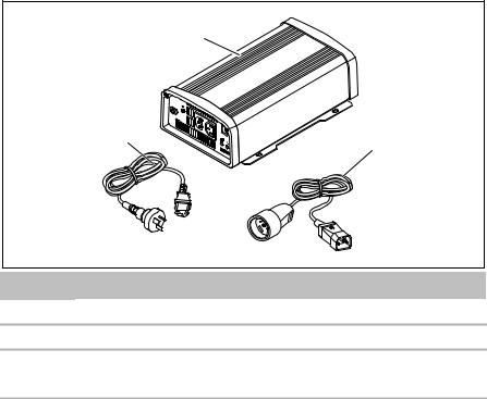
MSI1812T
2
1
3
2
No. Designation
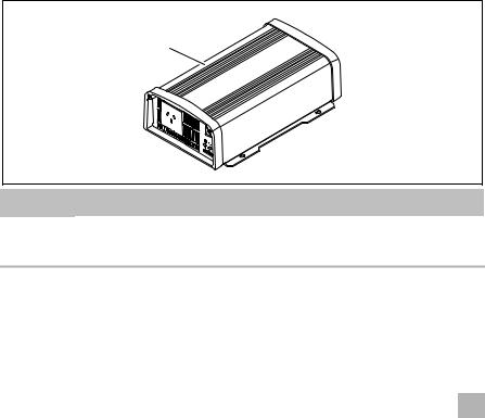
1Sine wave inverter
2Connection cable with safety coupling (for 230 Vw output)
3 |
Connection cable with safety plug (for 230 Vw supply) |
|
|
–Operating manual
4Accessories
Designation |
Ref. no. |
|
|
Remote control |
MCR-7 (on/off sleep mode) |
|
|
Remote control |
MCR-9 (LED power monitoring) |
|
|
5Target group for this manual
The electrical installation (chapter “Connecting the inverter” on page 15) is intended for professionals who are familiar with the applicable regulations of the country in which the equipment is to be installed and/or used.
All other chapters are intended for the users.
EN |
7 |
|
|
|
|

Intended use |
MSI |
6Intended use
!WARNING!
Never use the inverter on vehicles where the positive terminal of the battery is connected to the chassis.
The wave inverter converts direct current of 12 Vg into a 200 – 240 V AC supply of 50 Hz or 60 Hz.
7Technical description
The inverters can be operated wherever a 12 Vg connection (MSI 912, MSI 1812T) is available. The light-weight and compact construction of this device allows for easy installation in mobile homes, commercial vehicles or motor and sailing yachts.
The output voltage corresponds to the household voltage from the socket (pure sine wave, THD < 3 %).
Please observe the values for constant output power and peak output power as indicated in chapter “Technical data” on page 29. Never connect devices that have a higher power requirement.
INOTE
Note when connecting devices with an electrical drive (such as power drills and refrigerators), that they often require more power than is indicated on the type plate.
The inverter has various protective mechanisms.
•Overvoltage shutdown: The inverter shuts itself off when the voltage exceeds the cut-off value. It restarts when the voltage returns to the restart value.
•Undervoltage shutdown: The inverter shuts itself off when the voltage sinks below the cut-off value. It restarts when the voltage rises to the restart value.
•Excess temperature shutdown: The inverter switches off when the temperature inside the device or the temperature on the cooling element exceeds a cut-off value. It restarts when the voltage rises to the restart value.
•Overload shutdown: The LED on the inverter indicates an operating fault (constant red light) when an excess load is connected or a short circuit has occurred. The fuse in the device must be pressed in again by hand after it is triggered by excess current.
•Incorrect polarity protection: The incorrect polarity protection prevents the wrong polarity when connecting the inverter.
8 |
EN |
|

MSI |
Technical description |
•Fuses (MSI1812T only): The LED on the inverter indicates an operating fault (constant red light). The fuse in the device must be pressed in again by hand after it is triggered.
INOTE
The individual values are found in the chapter “Technical data” on page 29.
The inverter can be switched to an energy-saving mode to prevent the connected battery from discharging too quickly.
The inverter can be easily controlled using the remote control (accessory).
The SinePower MSI 1812T inverters are fitted with a 230 Vw priority circuit. If an external 230 Vw voltage is available, this will have priority. If no external 230 Vw voltage is connected, then the connected battery will be used as the power supply.
EN |
9 |
|
|
|
|

Technical description |
MSI |
7.1Control elements
The inverter has the following connections, displays and control elements on the back:
3
1 |
2 |
3 |
4 |
5 |
A ENB x ENB x GND
B N.O. x COM x N.C.
DC INPUT
1 


REMOTE
A
B
1
2
CHASSIS
GROUND
|
|
|
NEG (-) POS (+) |
|
5 |
4 |
3 |
No. |
Designation |
|
Description |
1 |
Terminal |
Setup operation via remote control |
|
2 |
REMOTE port |
Connection of a PC using a serial RS-232 interface or |
|
|
|
connection of the MCR-7 or MCR-9 remote control |
|
3 |
POS+ |
Positive terminal |
|
4 |
NEG– |
Negative terminal |
|
5 |
Earth terminal |
Earthing on the vehicle bodywork |
|
10 |
EN |
|
 Loading...