


RM2862
Dometic RM2862, RM2852, RM 2663, RM 2662, RM 2554 User Manual
...
DIAGNOSTIC SERVICE MANUAL
AMERICANA & AMERICANA PLUS
RM 2351, RM 2354, RM 2451, RM 2454
RM 2551, RM 2554, RM 2652, RM 2662
RM 2663, RM2852, RM2862 & NDR1062
USA
SERVICE OFFICE
Dometic Corporation
2320 Industrial Parkway
Elkhart, IN 46516
574-294-2511
CANADA
Dometic Distribution
46 Zatonski Unit 3
Brantford, Ontario
CANADA N3T 5L8
519-720-9578
For Service Center
Assistance Call:
800-544-4881
Form No. 3311143.000 02/07
©2007 Dometic Corporation
LaGrange, IN 46761
Foreword
This service manual is the result of the dedication of The Dometic Corporation Technical staff
and its engineers in giving service people the
necessary instruction for making accurate analyses of certain conditions. Provided is a diagnos-
tic chart leading a qualied mechanic into the
service manual pages to locate and solve symptoms which may occur. Dometic has continued
its commitment in providing service people with
this, the most up-to-date information about servicing Dometic RV accessories.
SAFETY INSTRUCTIONS
This manual has safety information and instructions to help users eliminate or reduce the risk
of accidents and injuries.
RECOGNIZE SAFETY INFORMATION
This is the safety-alert symbol. When you see this
symbol in this manual, be alert to the potential
for personal injury.
Follow recommended precautions and safe operating instructions.
UNDERSTAND SIGNAL WORDS
A signal word , WARNING OR CAUTION is used
with the safety-alert symbol. They give the level
of risk for potential injury.
Indicates a potentially hazard-
ous situation which, if not avoided, could result
in death or serious injury.
Indicates a potentially hazard-
ous situation which, if not avoided may result in
minor or moderate injury.
When used without the safety
alert symbol indicates, a potentially hazardous
situation which, if not avoided may result in property damage.
Read and follow all safety information and instructions.
1

CONTENTS
DIAGNOSTIC FLOW CHART............................................................................. 4
PAGE NO.
SECTION 1
OPERATION
Refrigerator Operation ........... ........................................................................6
SECTION 2
AC VOLTAGE
AC Voltage Requirements................ ...........................................................9
SECTION 3
AC COMPONENTS
Heating Element ....................... ...............................................................10
SECTION 4
DC VOLTAGE
DC Voltage Requirements ............... ........................................................10
SECTION 5
DC COMPONENTS
5.1 DC heating Element ................................ ..................................11
5.2 Thermistor ............................ .....................................................11
5.3 Solenoid Valve.................................... .......................................11
5.4 Igniter ........................ ................................................................11
5.5 High Voltage Cable ................................. ..................................12
5.6 Electrode ....................................................................................12
5.7 DC Relay ....................................................................................12
5.8 Upper Circuit Board ....................... ............................................13
5.9 Lower Circuit Board ....................... ............................................13
5.10 Door Switch ......................... ......................................................18
5.11 Climate Control Heater & Switch ................................ ...............18
5.12 Low Ambient Switch ............... ...................................................18
5.13 Fuses .........................................................................................18
5.14 Thermofuse ................................................................................18
SECTION 6
LP GAS
LP Gas Requirements ................... ......................................................19
SECTION 7
LP GAS COMPONENTS
7.1 Manual Gas Shut-Off Valve .................. .....................................19
7.2 Orice ................................... .....................................................19
7.3 Thermocouple .............................. .............................................20
7.4 Burner .................................... ...................................................20
2

CONTENTS
PAGE NO.
SECTION 7
7.5 Flue Bafe.............................................................................................20
7.6 Flue Cap ..............................................................................................20
7.7 Flue Tube .............................................................................................20
SECTION 8
COOLING UNIT
8.1 Leveling......................... ........................................................................21
8.2 Ventilation ..............................................................................................21
8.3 Air Leaks......................... .......................................................................23
8.4 Interior Liner Seal to Frame ...................................................................23
8.5 Door Position .........................................................................................24
8.6 Ambient Temperature ............................................................................24
8.7 Cooling Unit ...........................................................................................25
8.8 Food Storage .........................................................................................26
8.9 High Humidity ........................................................................................26
SECTION 9
WIRING
9.1 Internal Wiring.............................. ........................................................26
9.2 External Wiring........................... ..........................................................26
9.3 Wiring Schematics.............................. ..................................................26
SECTION 10
ICE MAKER
10.1 Operation.............................. ..............................................................26
10.2 Mold Heater........................... .............................................................27
10.3 Ice Ejector.............................. .............................................................27
10.4 Mold Thermostat......................... ........................................................27
10.5 Shut Off Arm................... ....................................................................27
10.6 Mold Switches........................... .........................................................27
10.7 Timing Motor........................... ............................................................28
10.8 Water Valve ........................................................................................28
10.9 Ice Maker Replacement... ...................................................................28
10.10 Water Fill Adjustment.................... ......................................................28
10.11 Water Supply.................. .....................................................................29
10.12 Wiring Schematics..............................................................................29
3
This program will address the most common system problems associated with the RM2351, RM2354, RM2451, RM2454,
RM2551, RM2554, RM2652 ,RM2662,RM2663,RM2852and RM2862 refrigerators supplied by The Dometic Corporation.
Our intent is to provide you with a guideline of checks to make, should you encounter one of the following symptoms.
SYMPTOM
1. No operation - no panel lights
2. No operation - has panel lights
3. No AC operation - operates on gas mode
4. No Gas operation - operates on AC mode
CAUSE
Operation
DC Volts
Fuse
Wiring
Upper Circuit Board
Lower Circuit Board
Operation
DC Volts
Thermistor
Wiring
Lower Circuit Board
Operation
AC Volts
Fuse
Heating Element
Wiring
Lower Circuit Board
Operation
LP Gas
Manual Gas Valve
Igniter
High Voltage Cable
Electrode
Solenoid
Wiring
Lower Circuit Board
SECTION & PAGE
1, page 06
4, page 10
5, page 18
9, page 26
5, page 13
5, page 13
1, page 06
4, page 10
5, page 11
9, page 26
5, page 14
1, page 07
2, page 09
5, page 19
3, page 11
9, page 24
5, page 13
1, page 06
6, page 19
7, page 19
5, page 11
5, page 12
5, page 12
5, page 11
9, page 24
5, page 13
5. Insufcient cooling on all modes.
6. Insufcient cooling on AC - cools properly
on gas mode.
7. Insufcient cooling on Gas - cools properly
on AC mode.
8. Freezes.
Ventilation
Leveling
Ambient Temperature
Air Leaks
Thermistor
Cooling Unit
AC Volts
Heating Element
Lower Circuit Board
LP Gas
Orice
Flue Bafe
Flue Tube
Burner
Lower Circuit Board
Operation
Thermistor
Lower Circuit Board
4
8, page 21
8, page 21
8, page 24
8, page 23
5, page 11
8, page 25
2, page 09
3, page 10
5, page 13
6, page 19
7, page 19
7, page 20
7, page 20
7, page 20
5, page 13
1, page 06
5, page 12
5, page 14

SYMPTOM
CAUSE
SECTION & PAGE
9. Check light on
10. Interior light on when door is closed
11. Rapid formation of frost
12. Water on frame
DC Volts
Wiring
LP Gas
Manual Gas Valve
Solenoid
Orice
Burner
Thermocouple
Lower Circuit Board
Wiring
Low Ambient Switch
Door Switch
Door Position
Food Storage
Interior Liner to Frame
High Humidity
Air Leaks
Interior Liner to Frame
High Humidity
Air Leaks
Climate Control Heater
4, page 10
9, page 26
6, page 19
7, page 19
5. page 11
7. page 19
7. page 20
7. page 20
5. page 13
9. page 26
5. page 18
5. page 18
8. page 24
8. page 26
8. page 23
8. page 26
8. page 23
8. page 23
8. page 26
8. page 23
5. page 18
5
SECTION 1
REFRIGERATOR OPERATION
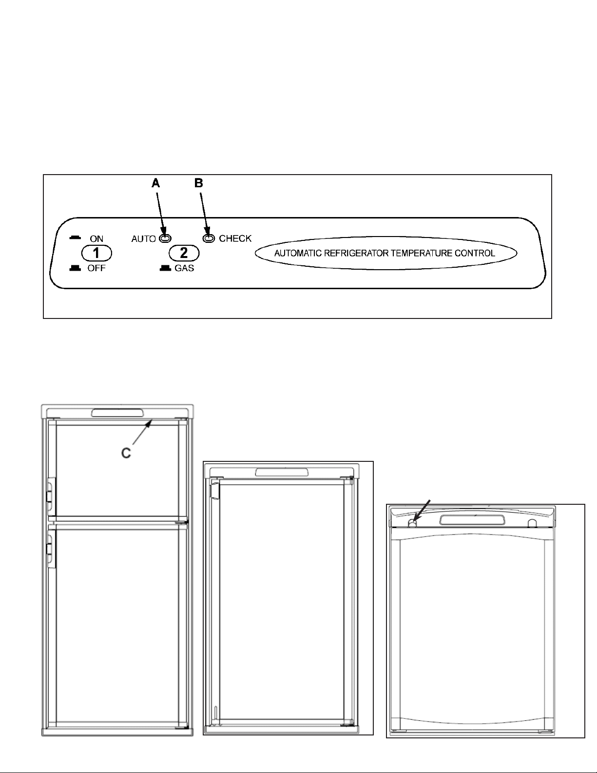
DISPLAY PANEL RM2351, RM2451, RM2551, RM2652, RM2852
AUTO TEMPERATURE CONTROL
Refrigerator Control Panel
RM2652 & RM2852
RM2662 & RM2862
RM2451 & RM2551
AMERICANA 2-WAY MODEL
1. Main Power Button ON/OFF
2. AUTO/GAS Mode Selector Button
A. AUTO Mode indicator lamp
B. CHECK indicator lamp (Gas Mode
Only)
C. Climate control switch only on
RM2652 & RM2862
Travel Latch
RM2351
6
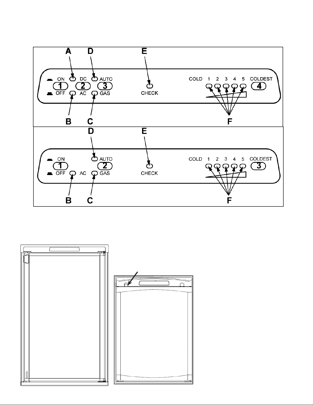
DISPLAY PANEL RM2354, RM2454, RM2554 RM2663 3-way
DISPLAY PANEL RM2662, RM2862 2-WAY
Refrigerator Control Panels
3-WAY
2-WAY
RM2454 & RM2554
Travel Latch
RM2354
3-WAY
1. Main Power Button ON/OFF
2. DC Mode Selector Button
3. AUTO/GAS Mode Selector Button
4. Temperature Selector Button
A. DC Mode Indicator Lamp
B. AC Mode Indicator Lamp
C. GAS Mode Indicator Lamp
D. AUTO Mode Indicator Lamp
E. CHECK Indicator Lamp
(Gas Operation Only)
F. Temperature Indicator Lamps
2-WAY
1. Main Power Button ON/OFF
2. AUTO/GAS Mode Selector Button
3. Temperature Selector Button
B. AC Mode Indicator Lamp
C. GAS Mode Indicator Lamp
D. AUTO Mode Indicator Lamp
E. CHECK Indicator Lamp
( GAS Mode Only)
F. Temperature Indicator Lamps
7
OPERATION INSTRUCTIONS
IMPORTANCE OF LEVELING A
REFRIGERATOR
In an absorption refrigerator system, ammonia is liqueed
in the nned condenser coil at the top rear of the refrigerator. The liquid ammonia then ows into the evaporator
(inside the freezer section) and is exposed to a circulat-
ing ow of hydrogen gas, which causes the ammonia to
evaporate, creating a cold condition in the freezer. When
starting this refrigerator for the very rst time, the cooling
cycle may require up to four hours of running time before the cooling unit is fully operational. The tubing in the
evaporator section is specically sloped to provide a continuous movement of liquid ammonia, owing downward
by gravity through this section. If the refrigerator is operated when it is not level and the vehicle is not moving, liquid ammonia will accumulate in sections of the evaporator
tubing. This will slow the circulation of hydrogen and ammonia gas, or in severe cases, completely block it, resulting in a loss of cooling. Any time the vehicle is parked for
several hours with the refrigerator operating, the vehicle
should be leveled to prevent this loss of cooling. The vehicle needs to be leveled only so it is comfortable to live in
(no noticeable sloping of oor or walls). When the vehicle
is moving, the leveling is not critical, as the rolling and
pitching movement of the vehicle will pass to either side
of level, keeping the liquid ammonia from accumulating in
the evaporator tubing.
OPERATION
Before starting the refrigerator, check that all the manual
gas valves are in the ON position. DO NOT forget the
manual shutoff valve on the rear of the refrigerator. This
refrigerator is equipped with a control system which can
be set to automatically select either 120 volt AC or LP gas
operation (AUTO mode), or if desired LP gas only (GAS
mode) or DC volts (DC Heater) where applicable.
Auto Thermostat
In both AUTO mode and GAS mode operation, the temperature is controlled by a factory preset temperature setting. The refrigerator controls will work down to 9.6 volt
DC.
Most LP gas appliances used in recreational vehicles are vented to the outside of the
vehicle. When parked close to a gasoline
pump, it is possible that the gasoline fumes
could enter this type of appliance and ignite
from the burner ame, CAUSING A FIRE OR
AN EXPLOSION.
FOR YOUR SAFETY, when refueling, shut
off all LP gas appliances which are vented
to the outside.
OPERATION
Auto Thermostat
A.
A continuous 12 volt DC supply must be available for
the electronic control to function.
B.
Press the main power ON/OFF button (1) to
the DOWN position.
C.
In AUTO mode, the AUTO lamp A will be illuminated.
The control system will automatically select between
AC and GAS operation with AC having priority. The
temperature is controlled by a factory preset temperature setting.
D.
In GAS mode operation, no lamps will be illuminated
and the temperature is controlled by a factory preset
temperature setting.
OPERATION
Adjustable Thermostat
A.
A continuous 12 volt DC supply must be available for
the electronic control to function.
B.
Press the main power ON/OFF button (1) to the DOWN
position.
C.
In AUTO mode, the AUTO lamp D will be illuminated.
The control system will automatically select between
AC and GAS operation with AC having priority. Temperature is selected by the user.
D.
In GAS mode operation, the GAS lamp C will be illuminated and only operate on LP only. Temperature is
selected by user.
E.
In DC mode, the DC lamp A will be illuminated and the
unit will only operate on DC until DC volts drops below
9.6 VDC.
Auto Mode
Press the AUTO/GAS button 2 (Auto Thermostat) or button 3 (Adjustable Thermostat) to the DOWN position. The
AUTO mode indicator lamp (A auto or D adjustable thermostat) will illuminate. If 120 volts AC is available, the
control system will select AC operation. If 120 volts AC is
not available, the control system will automatically switch
to GAS operation. Within 45 seconds the burner should
be ignited and operating normally. If the CHECK indicator
lamp (B auto or E adjustable thermostat) illuminates, the
control has failed to ignite the burner on GAS. To reset
when the CHECK indicator lamp, press the main power
ON/OFF button (1) to the OFF then ON position. Systems with the new lower control board are a three (3) try
system on gas. On the initial refrigerator start-up on gas
(120 volts AC is not available), it may take longer than 45
seconds to allow air to be purged from the gas line. If the
refrigerator has not been used for a long time or the LP
tanks have just been relled, air may be trapped in the
supply lines. To purge the air from the lines may require
resetting the main power ON/OFF button (1) three or four
times. If repeated attempts fail to start the LP gas operation, check to make sure that the LP gas supply tanks are
not empty and all manual shutoff valves in the lines are
open.
8

Note: Do not continue to reset GAS operation if the
CHECK indicator lamp continues to be illuminated after
several tries.
GAS Mode
Move the AUTO/GAS button 2 (Auto Thermostat) or button
3 (Adjustable Thermostat) to the UP position. The AUTO
mode indicator lamp (A) will go off. Within 45 seconds the
burner should be ignited and operating normally.
DC Mode 3 Way Units Only
Press the DC mode indicator button (2) to the DOWN
position. (Lamp [A] will light). Press the TEMPERATURE
SELECTOR button (4) until the lamp (F) at the desired
position is illuminated. The refrigerator will continue to operate in the DC mode until switch (2) is moved to the UP
position or control voltage falls below 9.6 VDC. The DC
mode overrides all the other operating modes. Discharging of the battery will occur if the vehicle engine is not
running.
Note: The DC mode is a holding mode not a full cooling mode. DC should be used once the unit is cooled
down and constant supply of DC available (driving
down the road).
To Shut Off The Refrigerator
The refrigerator may be shut off while in any mode of
operation by pressing the main power ON/OFF button to
the UP (OFF) position. This shuts off all DC power to the
control system.
Description Of Operating Modes
Auto Mode
When operating in the AUTO mode, the AUTO mode indicator lamp (A) will illuminate. The control system will
automatically select between AC and GAS operation with
AC having priority over GAS. If the control system is operating with AC energy and it then becomes unavailable,
the system will automatically switch to GAS. As soon as
AC becomes available again the control will switch back
to AC operation. Gas operation (120 volts AC is not avail-
able). The control system will activate the ignition system and will make three attempts to light the burner for
a period of approximately 45 seconds with two minutes
rest (purge) interval. If unsuccessful, the CHECK indicator lamp (B) will illuminate. To restart an ignition attempt
with the CHECK lamp illuminated or to clear (turn off) the
CHECK lamp, press the main power ON/OFF button to
the OFF position and wait a few seconds, then return to
the ON position. The control system will attempt a new ignition sequence. If 120 volts AC becomes available while
the CHECK indicator lamp is on, the CHECK lamp will not
turn off until the main power ON/OFF button is pressed
to the OFF then ON position but the unit will operate on
AC.
Gas Mode
When operating in the GAS mode, the AUTO mode indicator lamp (A) will be off. This mode provides LP gas operation only. The control system will activate the ignition
system and will make three attempts to light the burner for
a period of approximately 45 seconds with two minutes
a period of approximately 45 seconds with two minutes (purge) interval after each trial. If unsuccessful, the
CHECK indicator lamp (B) will illuminate. To restart GAS
operation, press the main power ON/OFF button (1) to
the OFF and then ON position. The control system will
attempt a new ignition sequence. If the refrigerator has
not been used for a long time or the LP tanks have just
been relled, air may be trapped in the supply lines. To
purge the air from the lines may require resetting the main
power ON/OFF button (1) three or four times. If repeated
attempts fail to start the LP gas operation, check to make
sure that the LP gas supply tanks are not empty and all
manual shutoff valves in the lines are turned on.
DC Mode 3 Way Units Only
Press the DC mode indicator button (2) to the DOWN
position. (Lamp [A] will light). Press the TEMPERATURE
SELECTOR button (4) until the lamp (F) at the desired
position is illuminated. The refrigerator will continue to operate in the DC mode until switch (2) is moved to the UP
position or control voltage falls below 9.6 VDC.
The DC mode overrides all the other operating modes.
Discharging of the battery will occur if the vehicle engine
is not running.
Note: The DC mode is a holding mode not a full cooling mode. DC should be used once the unit is cooled
down and constant supply of DC available (driving
down the road).
To Shut Off The Refrigerator
The refrigerator may be shut off while in any mode of
operation by pressing the main power ON/OFF button to
the UP (OFF) position. This shuts off all DC power to the
control system.
Limp Mode
This control system contains a feature where it will continue to operate the cooling system in event of a failure of
a major operating component. If the control cannot read
the temperature sensor and control to the preset temperature, then the control will run the cooling unit continuously at the energy source available. The refrigerator will
continue to operate in this mode indenitely or until a new
sensor is installed and the system is reset.
SECTION 2 AC VOLTAGE
AC VOLTAGE REQUIREMENTS
This is an energized circuit. Shock can occur
if not tested properly. Testing is to be done
by a qualied service technician.
The proper operating range is 100 to 132 volts. If voltage
drops below 100 volts, cooling efciency will decrease
with voltage decrease.
9
The refrigerator will not switch to another mode of operation until all AC power is lost. The refrigerator is equipped
with a three-prong (grounded) plug for protection against
shock hazards, and should be plugged directly into a
properly grounded three-prong receptacle.
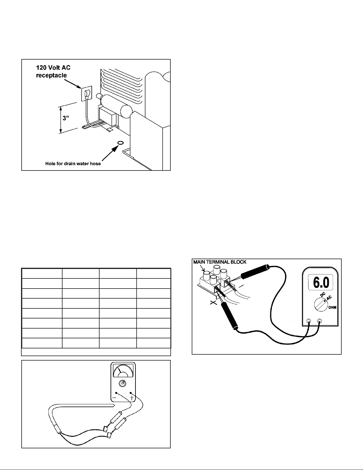
SECTION 3 AC COMPONENTS
Heating Element
The heating element is designed to deliver a predetermined amount of heat to the cooling unit. To check a heating element, remove the heater leads from the printed
circuit board and measure for proper resistance across
the two leads with a properly calibrated ohm meter. This
check is to be done with the heating element at room
temperature. You should obtain the following readings ±
10%:
SECTION 4 DC VOLTAGE
DC Voltage Requirements
Clean Direct Current (DC) power is mandatory for hightech circuits to operate as designed. A battery will provide
straight line DC power. The converter and alternator produce DC power by a series of diodes that rectify alternating current to DC. The Dometic control system will only
tolerate up to 6 AC volts on the DC line. AC ripple can be
measured by a digital voltmeter set on the AC scale at the
main DC terminal block connections at the refer. Six volts
AC or less is acceptable. If AC volts exceed 6 on the DC
incoming line the power source should be cleaned up. AC
voltage in excess of 6 volts will affect the processor and
create erratic operation. When testing for AC ripple on the
DC line put a load on the converter. The operational range
of the unit is a minimum of 9.6V DC to a maximum of
22V DC. The unit will automatically shut down until voltage has decreased to 18V DC. The refrigerator requires
at least 9.6V DC for proper operation; however the panel
lights will continue to illuminate until voltage has dropped
to 4V DC or below. Do not use the body or chassis of
the RV as a substitute for either of the two conductors.
The refrigerator must be connected to the battery circuit
with two wires of adequate capacity to avoid voltage drop.
Proper polarity is crucial for refrigerator operation.
No other electrical equipment or lighting should be
connected to the refrigerator circuit. Just because you
can read volts does not mean you have the amps to operate the control system. If relays buzz, lights go dim or out
during operation, this could indicate there is a loose connection somewhere.
Main Terminal Block
Model WATTS OHMS AMPS
RM2351-4 175 80 1.5
RM2451-4 175 80 1.5
RM2551-4 175 80 1.5
RM2652 325 44 2.7
RM2662-3 325 44 2.7
RM2852 325 44 2.7
RM2862 325 44 2.7
Never over or under size the AC heater.
Grounds
The operation of the Dometic refrigerator is also dependent on good, clean ground connections. Loose or corroded ground terminals create an unknown resistance factor
that can affect the voltage detected by the Power Module.
A loose negative DC wire will create a negative millivolt
signal that the control board will pick up and create erratic
operation. Check the integrity of the grounds from the refrigerator all the way to the power source/battery. Clean or
tighten any suspicious looking connections.
Note: The DC terminal block below the control board
should be cleaned and tightened at the 4 wires.
10
 Loading...