


Dometic RM2554, RM2551, RM2354, RM2451, RM2351 User Manual
...OPERATING INSTRUCTIONS
RM2351 RM2454 DM2652 DM2852
RM2354 RM2551 DM2662 DM2862
RM2451 RM2554 DM2663 NDM1062
FIRE OR EXPLOSION HAZARD
If you smell gas:
1.Open windows.
2.Do not attempt to light appliance.
3.Do not touch electrical switches.
4.Extinguish any open flame.
5.Shut off fuel supply.
6.Evacuate immediately and call emergency services.
Failure to follow these instructions could result in fire or explosion, which could cause property damage, personal injury, or death.
FOR YOUR SAFETY
Do not store or use gasoline or other flammable vapors and liquids in the vicinity of this or any other appliance.
Improper installation, adjustment, alteration, service or maintenance can cause injury or property damage. Refer to this manual. For assistance or additional information consult a qualified installer, service agency or the gas supplier.
If the refrigerator stops cooling - or - if it emits an ammonia smell, immediately turn the refrigerator off and contact a Service Center.
REVISION D
Form No. 3313240.016 12/17 (French 3313241.013_D) ©2017 Dometic Corporation LaGrange, IN 46761
USA & CANADA |
SERVICE CENTER & |
SERVICE OFFICE |
DEALER LOCATIONS |
Dometic Corporation |
Please Visit: |
1120 North Main Street |
www.dometic.com |
Elkhart, IN 46514 |
|

INTRODUCTION
Thank you for purchasing a new Dometic refrigerator. This product is a recreational vehicle refrigerator intended for the storage of fresh and frozen foods, as well as making ice.
Appearance of your product may vary from illustrations shown in this document.
Please read and be aware of possible safety hazards identified in this manual, and become familiar with the alert symbols on the refrigerator. Read this manual carefully so that you know how to operate the refrigerator safely and correctly. Keep this manual with the refrigerator for future reference.
CONTENTS |
|
REFRIGERATOR OVERVIEW. . . . . . . . . . . . . . . . . . . . . . . . . . . . . . . . . . . . . . . . . . . . . . . . . . . . . . . . . . . . . . . . . . . . . . . . . . . |
. 3 |
INSTRUCTIONS FOR USE.............................................................................. |
6 |
STORAGE COMPARTMENTS. . . . . . . . . . . . . . . . . . . . . . . . . . . . . . . . . . . . . . . . . . . . . . . . . . . . . . . . . . . . . . . . . . . . . . . . . . . . |
9 |
PRODUCT CARE.. . . . . . . . . . . . . . . . . . . . . . . . . . . . . . . . . . . . . . . . . . . . . . . . . . . . . . . . . . . . . . . . . . . . . . . . . . . . . . . . . . . . |
10 |
MAINTENANCE & SERVICE .. . . . . . . . . . . . . . . . . . . . . . . . . . . . . . . . . . . . . . . . . . . . . . . . . . . . . . . . . . . . . . . . . . . . . . . . . . . |
12 |
TROUBLESHOOTING .. . . . . . . . . . . . . . . . . . . . . . . . . . . . . . . . . . . . . . . . . . . . . . . . . . . . . . . . . . . . . . . . . . . . . . . . . . . . . . . . |
14 |
APPENDIX A - SPARE PARTS. . . . . . . . . . . . . . . . . . . . . . . . . . . . . . . . . . . . . . . . . . . . . . . . . . . . . . . . . . . . . . . . . . . . . . . . . . . |
15 |
APPENDIX B - REARVIEW EQUIPMENT . . . . . . . . . . . . . . . . . . . . . . . . . . . . . . . . . . . . . . . . . . . . . . . . . . . . . . . . . . . . . . . . . . |
17 |
APPENDIX C - WIRING DIAGRAM . . . . . . . . . . . . . . . . . . . . . . . . . . . . . . . . . . . . . . . . . . . . . . . . . . . . . . . . . . . . . . . . . . . . . . . |
19 |
APPENDIX D - CONSUMER SUPPORT .. . . . . . . . . . . . . . . . . . . . . . . . . . . . . . . . . . . . . . . . . . . . . . . . . . . . . . . . . . . . . . . . . . |
24 |
APPENDIX E - DOMETIC WARRANTY.. . . . . . . . . . . . . . . . . . . . . . . . . . . . . . . . . . . . . . . . . . . . . . . . . . . . . . . . . . . . . . . . . . . |
25 |
APPENDIX F - MAINTENANCE SCHEDULE.. . . . . . . . . . . . . . . . . . . . . . . . . . . . . . . . . . . . . . . . . . . . . . . . . . . . . . . . . . . . . . . |
26 |
SYMBOLS
The following symbols are used throughout this manual:
This is the safety alert symbol. It is used to alert you to personal injury hazards. Obey all safety messages that follow this symbol to avoid possible injury or death.
WARNING indicates a hazardous situation which, if not avoided, could result in death or serious injury.
CAUTION, used with the safety alert symbol, indicates a hazardous situation which, if not avoided, could result in minor or moderate injury.
NOTICE is used to address practices not related to personal injury.
Information
Step-by-step instructions
2

REFRIGERATOR OVERVIEW
ABSORPTION COOLING SYSTEM
When turning on the refrigerator, you should adjust the thermostat (excludes RM2351, RM2451, RM2551, DM2652 & DM2852 - not adjustable) to the coldest temperature setting. The cooling cycle may require an extended running time before cooling effect is observed.
WHEN THE REFRIGERATOR IS NOT IN USE
Any absorption refrigerator that is to be taken out of service for an extended period of time should be turned off.
It is important that you do not leave the refrigerator to run idle and/or unattended for days or weeks.
LEVELING THE REFRIGERATOR
Leveling is one of the requirements for proper operation with absorption refrigerators. To ensure proper leveling the vehicle needs to be leveled so it is comfortable to live in
(no noticeable sloping of floor or walls).
Any time the vehicle is parked for several hours with the refrigerator operating, the vehicle should be leveled to allow proper cooling.
When the vehicle is moving, the leveling is not critical, as the rolling and pitching movement of the vehicle will pass to either side of level, keeping the liquid ammonia from accumulating in the evaporator tubing.
OPERATING REFRIGERATOR AT HIGH ALTITUDE
All gas appliances experience lowered efficiency (or rating) at high altitude This is a direct result of lower atmospheric pressure and oxygen levels, and is not a defect of the refrigerator.
Reduced cooling performance and burner outage may occur at altitudes higher than 5500 feet above sea level (while operating on LP gas). Always operate refrigerator on electric power at altitudes higher than 5500 feet.
PURGING AIR FROM THE LINES
If the refrigerator has not been used for a long time - or - the LP tanks have just been refilled, air may be trapped in the supply lines. To purge the air from the lines, turn the refrigerator off and on by pressing the ON/OFF button. If the flame is not lit within 45 seconds, turn the refrigerator off and back on again. This procedure can be repeated 3 to 4 times. If repeated attempts fail to start the LP gas operation, check to make sure that the LP gas supply tanks are not empty and that all manual shutoff valves in the lines are open. If the problem persists, turn the refrigerator off and take it to a Service Center.
AUTOMATIC ENERGY SELECTOR SYSTEM
The refrigerator is equipped with an automatic energy selector system. The user turns the refrigerator on and then, the refrigerator automatically selects the most suitable energy source available, either 120 VAC or LP gas operation. The system can be set by the user to be fully automatic (AUTO mode is selected) or to operate on LP gas only (AUTO mode is off).
On 3-way models, the control system can manually be set to DC mode (DC operation). The DC mode overrides all other operating modes.
The refrigerator controls will work down to 9.6 VDC.
3

REFRIGERATOR OVERVIEW
CONTROL PANEL
RM2351, RM2451, RM2551, DM2652 & DM2852
|
A |
B |
|
ON |
AUTO |
2 |
CHECK |
1 |
|
AUTOMATIC REFRIGERATOR TEMPERATURE CONTROL |
|
OFF |
|
GAS |
|
RM2354, RM2454, RM2554 & DM2663 |
|||
A |
D |
|
E |
ON |
DC |
AUTO |
COLD 1 2 3 4 5 COLDEST |
1 |
2 |
3 |
4 |
OFF |
AC |
GAS |
CHECK |
B |
C |
|
F |
1.ON/OFF button (main power)
2.AUTO/GAS mode selector button
A.AUTO mode indicator lamp
B.CHECK indicator lamp (GAS mode only)
1.ON/OFF button (main power)
2.DC mode selector button
3.AUTO/GAS mode selector button
4.Temperature selector button
A.DC mode indicator lamp
B.AC mode indicator lamp
C.GAS mode indicator lamp
D.AUTO mode indicator lamp
E.CHECK indicator lamp (GAS mode only)
F.Temperature indicator lamps
DM2662, DM2862 & NDM1062
A D
ON |
|
AUTO |
COLD 1 2 3 4 5 COLDEST |
1 |
|
2 |
3 |
OFF |
AC |
GAS |
CHECK |
B |
C |
|
E |
|
NDM1062 |
|
|
|
|
|
B |
D |
|
|
ON |
AES |
COLD 1 2 3 4 5 COLDEST |
CLC |
LAC |
AUTO |
||||
1 |
2 |
3 |
4 |
5 |
OFF AC |
GAS |
CHECK |
|
|
A |
C |
E |
F |
G |
1.ON/OFF button (main power)
2.AUTO/GAS mode selector button
3.Temperature selector button
A.AUTO mode indicator lamp
B.AC mode indicator lamp
C.GAS mode indicator lamp
D.CHECK indicator lamp
E.Temperature indicator lamps
1.ON/OFF button (main power)
2.AES/AUTO/GAS mode selector button
3.Temperature selector button
4.Climate control button
5.Low ambient control button
A.AC mode indicator lamp
B.AES/AUTO mode indicator lamp
C.GAS mode indicator lamp
D.CHECK indicator lamp
E.Temperature indicator lamps
F.Climate control indicator lamp
G.Low ambient control indicator lamp
4

REFRIGERATOR OVERVIEW
MODES OF OPERATION
AUTO MODE - AES/AUTO MODE
When operating in AUTO - AES/AUTO mode, the AUTO - AES/AUTO mode indicator lamp is illuminated. The control system will automatically select between AC and GAS operation. AC has priority over GAS. Should AC become unavailable, the system automatically switches to GAS.
As soon as AC becomes available again, the control will switch back to AC regardless of the status of the GAS operation.
If the CHECK indicator lamp is illuminated the controls have failed to ignite the burner in the GAS mode. To restart an ignition attempt with the CHECK lamp illuminated (or to turn off the CHECK lamp), press the ON/OFF button OFF and back ON again. The control system activates the ignition system and makes three attempts to light the burner for a period of approximately 45 seconds at two minutes interval. Should 120 VAC become available while the CHECK indicator lamp is on, the CHECK lamp will not turn off until the ON/OFF button is pressed OFF and then ON again.
GAS MODE
RM2351, RM2451, RM2551, DM2652 & DM2852:
When operating in GAS mode, the AUTO mode indicator lamp will be off.
RM2354, RM2454, RM2554, DM2662, DM2663, DM2862 &
NDM1062: When operating in GAS mode, the GAS Mode indictor lamp is illuminated.
This mode provides LP gas only. The control system activates the ignition system and attempts to light the burner for a period of approximately 45 seconds at two minutes interval. If unsuccessful, the CHECK indicator lamp will illuminate.
To restart GAS operation, press the ON/OFF button to OFF and then back ON. The control system attempts a new ignition sequence.
DC MODE
RM2354, RM2454, RM2554 & DM2663
When operating in DC mode (3-way models only), the DC mode indicator lamp is illuminated and all other lamps are off. To select another operating mode, turn off the DC mode by pressing the DC selector button. The DC lamp is turned off.
When there is no charging of the house battery, switch to AUTO mode or GAS mode since running the refrigerator on 12 VDC will quickly drain the battery.
LIMP MODE OF OPERATION
In the event of a failure of a major operating component, the control system will continue to operate the cooling system.
RM2351, RM2451, RM2551, DM2652 & DM2852
If the control can not read the temperature sensor and control the preset temperature, the control will run the cooling unit continuously at the energy source available. The refrigerator will continue to operate in this mode indefinitely - or - until a new sensor is installed and the system reset.
RM2354, RM2454, RM2554, DM2662, DM2663, DM2862 &
NDM1062
Two modes of operation can occur:
1)The first limp mode of operation will execute if the display module becomes non functional. The control system reverts to full automatic operation selecting the best energy source available with AC, DC (3- way only) and GAS priority. The temperature setting is maintained at the mid position. The power module will continually attempt to reestablish operation of the display module.
2)The second limp mode of operation will execute when a failure of the temperature sensing device or associated electronic circuitry occurs. If this should happen, the control system operates on the energy source selected via the control panel. The cooling unit runs continuously on the selected energy source. The refrigerator continues to operate in this mode indefinitely or until a new sensor is installed and the system is reset.
5
INSTRUCTIONS FOR USE
STARTING THE REFRIGERATOR
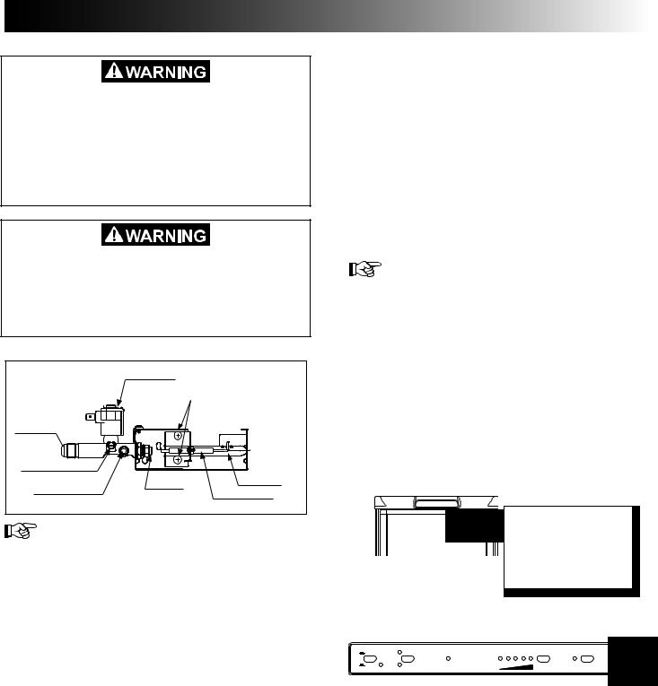
FIRE HAZARD. When the RV has not been used for some time, make sure that the path between the burner jet and the burner tube has not been obstructed before lighting the LP gas burner. Failure to obey this warning could cause a fire resulting in death or serious injury.
FIRE OR EXPLOSION HAZARD. When refueling or parked near gasoline pumps shut off all LP gas appliances. Failure to obey this warning could cause a fire or explosion resulting in death or serious injury
LP GAS EQUIPMENT ASSEMBLY
|
SOLENOID VALVE |
|
|
|
BURNER MOUNTING SCREWS |
INLET FITTING |
|
|
MANUAL SHUTOFF VALVE |
|
|
Shown in open position |
|
BURNER TUBE |
|
BURNER JET |
|
PRESSURE TEST PORT |
|
|
|
SPARK ELECTRODE |
|
|
|
1.Check that all the manual gas valves are in the ON position.
2.Make sure that a continuous 12 VDC supply is available for the electronic control to function.
3.Press the ON/OFF button.
4.Select operation mode:
--AUTO - AES/AUTO mode (AC and Gas) Press the AUTO/GAS - AES/AUTO/Gas mode selector button (if not already on). The illuminated lamp indicates the selected mode.
(If the CHECK indicator lamp is illuminated, see REFRIGERATOR OVERVIEW > MODES OF OPERATION > AUTO MODE - AES/AUTO MODE for further information.)
--GAS mode (LP gas operation only) Press the AUTO/GAS - AES/AUTO/Gas mode selector button to turn off the AUTO mode (if
not already off). |
|
(Within 45 seconds the burner should be ig- |
|
nited and operating normally. If not, see RE- |
|
FRIGERATOR OVERVIEW > MODES OF |
|
OPERATION > GAS MODE for further infor- |
|
mation.) |
6 |
|
--DC mode (3-way models only)
Press the DC mode indicator button. The DC lamp will be turned on. To select AUTO or GAS mode, turn off the DC mode by pressing the DC mode selector button. The DC lamp will then be turned off.
ADJUSTING THE THERMOSTAT
RM2354, RM2454, RM2554, DM2662, DM2663, DM2862
& NDM1062
The thermostat controls both the gas and electric operation, thereby eliminating the necessity of resetting each time a different energy source is employed. After the initial start-up, the thermostat should be adjusted to the desired temperature setting.
1.Press the temperature selector button until the lamp at the desired setting is illuminated.
RM2351, RM2451, RM2551, DM2652 & DM2852
The temperature is controlled by a factory preset temperature setting.
COLD WEATHER LOW AMBIENT CONTROL
NDM1062
The refrigerator is equipped with an exclusive feature that allows for trouble-free operation in low ambient temperature (like below 50°F) for extended periods of time. Once the outdoor temperature is above 50°F, the low ambient switch should be turned off.
 1. Turn the Low ambient control switch to I (ON).
The Low ambient control switch is located beneath the top decoration panel that houses the control panel.
2.Press the LAC button. The indicator lamp will illuminate.
ON |
|
AES |
COLD 1 2 3 4 5 COLDEST |
CLC |
LAC |
|
AUTO |
||||
OFF |
AC |
GAS |
CHECK |
|
|
INSTRUCTIONS FOR USE
EXTREME COLD WEATHER OPERATION
Refrigerator performance may be reduced in extremely cold (subzero) temperatures. This temporary condition is normal for absorption refrigerators and does not indicate product failure. In the event that performance is reduced in such conditions, turn the refrigerator off. As ambient temperatures rise, please restart your refrigerator according to instructions before requesting service.
CLIMATE CONTROL SYSTEM
NDM1062
During the summer months of high temperature and humidity, the metal frame between the freezer and fresh food compartments may have water droplets forming. The number of water droplets will increase if the vehicle is not air conditioned during these months. The refrigerator comes standard with a 12 VDC climate control that will evaporate the water droplets when they form. The climate control can be left on continuously or used only when temperatures require it. Note that when turned on, the climate control will draw 12 VDC power continuously. Turn it off when a
charging source is not available.
 1. Turn the climate control switch to I (ON).
The Climate control switch is located beneath the top decoration panel that houses the control panel.
2.Press the CLC button. The indicator lamp will illuminate.
ON |
|
AES |
COLD 1 2 3 4 5 COLDEST |
CLC |
LAC |
|
AUTO |
||||
OFF |
AC |
GAS |
CHECK |
|
|
OPERATING THE ICE MAKER
(ICE MAKER MODELS ONLY)
Before the ice maker can operate, make sure that:
•The refrigerator is connected to 120 VAC .
•The water valve supplying the refrigerator is turned on.
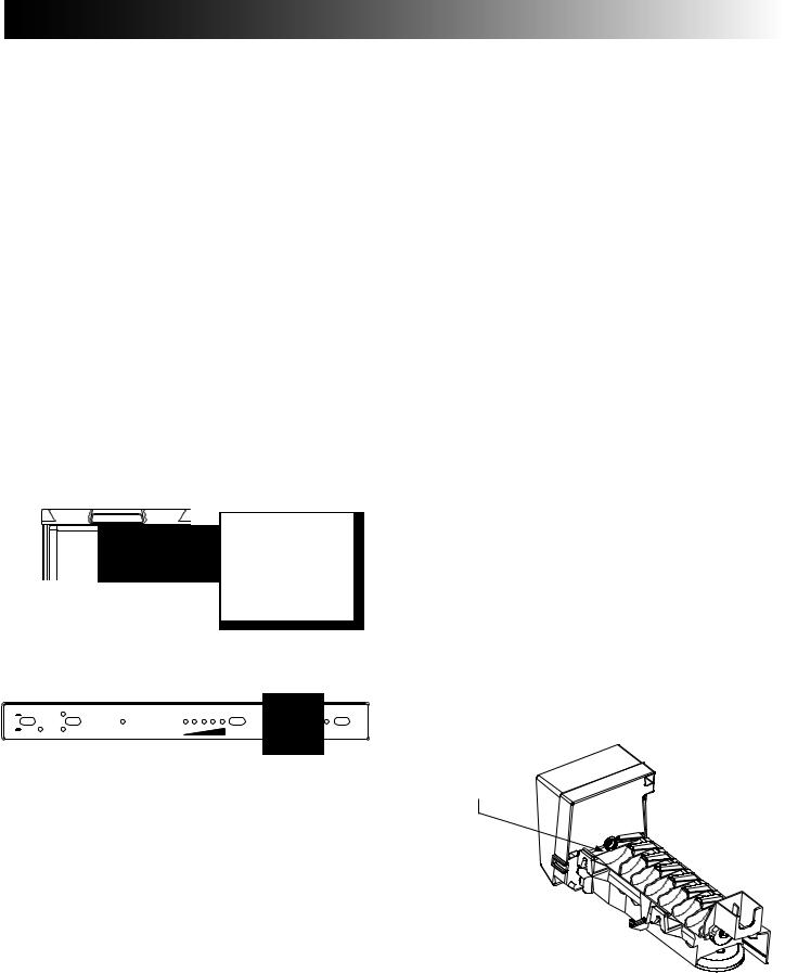
•The ice level bail arm is in its fully down position.
Keep bail arm in the up (OFF) posi - tion until water is present at the ice maker.
Ice level bail arm
Down position
When the ice maker thermostat senses the preset temperature for the ejection of the ice cubes, the fingers will start to rotate,dumpinganyicecubesandfillingthemoldwithwater.
When the storage container is full, the bail arm will come in contact with the ice cubes. The bail arm cannot return to the full down position and the ice production is stopped until the bin is emptied, or ice cubes are removed.
To prevent water from splashing out of the mold assembly while travelling in your recreational vehicle, raise the bail arm to the full UP/OFF position about 1-1/2 hours before departing. This will allow the water in the mold to freeze.
WATER SUPPLY
The water supply system must have a minimum pressure of 15 pounds per square inch gauge (psig). A 1/4” diameter water line to the water valve should be used at the rear of the refrigerator. The water line must have a manual shutoff valve placed where it is easily accessible.
The maximum water level is represented by a thin line. It is essential that the water level does not exceed this line!
Maximum water level
If necessary,change the water flow by adjusting the water supply. For instructions, see ADJUSTING THE SIZE OF CUBES.
7

INSTRUCTIONS FOR USE
ADJUSTING THE SIZE OF CUBES
If the ice maker was cleaned and drained, no ice
cubes will be dumped into the bin during the first cycle.
The first few cycles may have small cubes due to air trapped in the water lines. The first container of ice cubes should be dumped if the water system has been winterized or not used for several weeks. Once the ice maker has run through several cycles and if cubes are too small or sticking together, adjustment is necessary on the amount of water entering the mold.
TO ADJUST THE SIZE OF CUBES, FOLLOW THESE
STEPS:
1.Remove the protective cover from the ice maker mechanism. Using a flat-head screwdriver, place the tip of the screwdriver in the slot. Twist the screwdriver blade gently to loosen the cover.
2.Locate the adjusting screw under the protective cover. Turn the screw counterclockwise to increase the size of cubes.
Adjusting screw
3.Turn the screw clockwise to decrease the cube size or if the mold is overfilling, and the cubes are stuck together.
To prevent overfilling, do not turn the adjustment screw more than one revolution at a time. Allow the ice maker to cycle several times before another adjustment is made. Be sure to replace the protective cover on the cycle after the adjustments are complete.
TURNING OFF THE REFRIGERATOR, AND
WHEN NOT IN USE
You can turn off your refrigerator by pressing the main power ON/OFF button found on the control panel to the OFF position. This will shut off all power to the refrigerator, including DC power to the refrigerator.
If the refrigerator will not be in operation for an extended period of time or put into winter storage it should be emp-
tied, defrosted, cleaned, and the doors placed in the airing
position. If ice cube trays are in use, they should also be dried and kept outside the cabinet.
This refrigerator is intended for continuous use. Do not allow it to run unattended when there is a risk for loss of electricity or fuel. Food spoilage could occur.
The refrigerator’s control system still consumes a few milliamps even if it is turned off. If your RV is being put into winter storage, it is recommended to either put your RV batteries on a battery charger or turn off the vehicle’s main 12 VDC switch. This will prevent the RV battery from discharging.
8
 Loading...