


EN DE FR ES IT NL DA SV NO FI PT RU PL
Awning
Installation Manual. . . . . . . . . . . . . . . 7
Markise
Montageanleitung . . . . . . . . . . . . . . 16
Store extérieuru
Instructions de montage . . . . . . . . . 26
Toldo
Instrucciones de montaje. . . . . . . . . 36
Tenda da sole
Indicazioni di montaggio . . . . . . . . . 46
Zonnescherm
Montagehandleiding . . . . . . . . . . . . 55
Markise
Monteringsvejledning. . . . . . . . . . . . 64
Markis
Monteringsanvisning . . . . . . . . . . . . 73
Markise
Monteringsanvisning . . . . . . . . . . . . 82
Markiisi
Asennusohje . . . . . . . . . . . . . . . . . . 91
Toldo
Instruções de montagem . . . . . . . . 100
Маркиза
Инструкция по монтажу. . . . . . . . 109
Markiza
Instrukcja montażu. . . . . . . . . . . . . 119
PerfectRoof
PR2000, PR2500
|
Markýza |
|
|
CS |
|
|
|
|
Návod k montáži . . . . . . . . . . . . . . |
128 |
|
|
Markiza |
|
|
SL |
|
|
|
|
Navodilo za montažo . . . . . . . . . . |
137 |
|
EL ΟδηγίεςΤέντα |
τοποθέτησης . . . . . . . . . . |
146 |
|
|
|
|
PR2000, PR2500 |
|
1 |
|
|
|
|
|
|
|
1 |
|
2 |
3 |
4 |
|
|
5 |
6 |
7 |
8 |
|
|
|
9 |
10 |
11 |
|
|
|
12 |
13 |
2

PR2000, PR2500 |
2 |
3
15 –
 25 Nm
25 Nm 


4


3
PR2000, PR2500 |
5 |
2. |
Ø 3 mm |
1. |
4

PR2000, PR2500
6 PR2000:
A |
|
|
|
|
B |
|
|
|
|
|
|
|
|
|
|
|
|
|
|
|
|
||
|
|
|
|
|
|
|
|
|
|
|
|
|
|
|
|
|
|
|
|
|
|
|
|
|
|
|
|
|
|
|
|
|
|
|
|
|
|
|
|
|
|
|
|
|
|
|
|
|
|
|
|
|
|
|
|
|
|
|
|
|
|
|
|
|
|
|
|
|
|
|
|
|
|
|
|
|
|
|
|
|
|
|
|
|
|
|
|
|
|
|
|
|
|
|
|
|
|
|
|
|
|
|
|
|
|
|
|
|
|
|
|
|
|
|
|
|
|
|
|
|
|
|
|
|
|
|
|
|
|
|
|
PR2500:
A |
|
|
|
|
|
B |
|
|
|
|
|
|
|
|
|
|
|
|
|
|
|
|
|
||
|
|
|
|
|
|
|
|
|
|
|
|
|
|
|
|
|
|
|
|
|
|
|
|
|
|
|
|
|
|
|
|
|
|
|
|
|
|
|
|
|
|
|
|
|
|
|
|
|
|
|
|
|
|
|
|
|
|
|
|
|
|
|
|
|
|
|
|
|
|
|
|
|
|
|
|
|
|
|
|
|
|
|
|
|
|
|
|
|
|
|
|
|
|
|
|
|
|
|
|
|
|
|
|
|
|
|
|
|
|
|
|
|
|
|
|
|
|
|
|
|
|
|
|
|
|
|
|
|
|
|
|
|
|
|
|
|
|
|
|
|
|
|
|
|
|
|
|
|
|
|
|
|
|
|
|
|
|
|
|
|
|
|
|
|
|
|
|
|
|
|
|
|
|
|
|
|
|
|
|
|
|
|
|
|
|
|
|
|
|
|
|
|
|
|
5
|
|
PR2000, PR2500 |
7 |
|
|
1. |
3. |
4. |
|
||
|
|
|
2. |
|
|
6

PR2000, PR2500
!WARNING!
This operating manual must be read and understood before installation, set up, operation and servicing. This device must be installed by a specialist. Improper installation can lead to serious injury. Alterations to the device can be extremely dangerous and lead to serious injury or damage to the device.
Keep this operating manual with the device. The owner must read it carefully.
Table of contents
1 Explanation of symbols . . . . . . . . . . . . . . . . . . . . . . . . . . . . . . . . . . . 8 2 Important safety and installation instructions . . . . . . . . . . . . . . . . . . . 8 3 Scope of delivery . . . . . . . . . . . . . . . . . . . . . . . . . . . . . . . . . . . . . . . . 9 4 Accessories . . . . . . . . . . . . . . . . . . . . . . . . . . . . . . . . . . . . . . . . . . . 11 5 Intended use . . . . . . . . . . . . . . . . . . . . . . . . . . . . . . . . . . . . . . . . . . 11 6 Installing the awning . . . . . . . . . . . . . . . . . . . . . . . . . . . . . . . . . . . . 12 7 Disposal . . . . . . . . . . . . . . . . . . . . . . . . . . . . . . . . . . . . . . . . . . . . . . 15
EN |
7 |

Explanation of symbols |
PR2000, PR2500 |
1 Explanation of symbols
!WARNING!
Safety instruction: Failure to observe this instruction can cause fatal or serious injury.
ANOTICE!
Failure to observe this instruction can cause material damage and impair the function of the product.
INOTE
Supplementary information for operating the product.
Action: This symbol indicates that action is required on your part. The required action is described step-by-step.
This symbol describes the result of an action.
Fig. 1 5, page 3: This refers to an element in an illustration. In this case, item 5 in figure 1 on page 3.
2Important safety and installation instructions
Please observe the prescribed safety instructions and stipulations from the vehicle manufacturer and service workshops.
The manufacturer accepts no liability for damage in the following cases:
Damage to the product resulting from mechanical influences and excess voltage
Alterations to the product without express permission from the manufacturer
Use for purposes other than those described in the operating manual
! If you do not have sufficient technical knowledge for installing components in vehicles, you should have a specialist fit the awning to your vehicle.WARNING!
8 |
EN |

PR2000, PR2500 |
Scope of delivery |
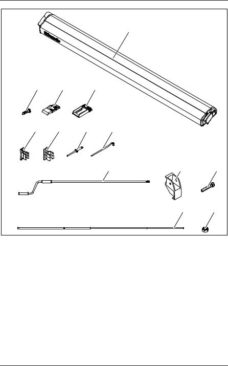
3 Scope of delivery
3.1PR2000
No. in |
Awning width |
|
|
|
|
|
|
fig. 1, |
2.6 m, 3 m, 3.25 m, |
4 m |
Description |
page 2 |
3.5 m, 3.75 m |
|
|
|
|
|
|
|
|
|
|
1 |
1x |
1x |
Awning |
|
|
|
|
2 |
6x |
6x |
Self-tapping screw |
|
|
|
|
3 |
2x |
2x |
Wall bracket (lower section) |
|
|
|
|
4 |
2x |
2x |
Wall bracket (upper section) |
|
|
|
|
5 |
1x |
1x |
Crank bracket (lower section) |
|
|
|
|
6 |
— |
— |
Crank bracket (upper section) |
|
|
|
|
7 |
4x |
4x |
Rivets |
|
|
|
|
8 |
4x |
4x |
Pegs |
|
|
|
|
9 |
1x |
1x |
Crank |
|
|
|
|
10 |
— |
1x |
Latch for tensioning arm |
|
|
|
|
11 |
— |
1x |
Hexagon head bolt |
|
|
|
|
12 |
— |
1x |
Tensioning arm |
|
|
|
|
13 |
— |
1x |
Hexagon nut with clamping part |
|
|
|
|
EN |
9 |

Scope of delivery |
PR2000, PR2500 |
3.2PR2500
No. in |
Awning width |
|
|
|
|
|
|
fig. 1, |
2.6 m, 3 m, |
4 m, 4.5 m, |
Description |
page 2 |
|
||
3.5 m, 3.75 m |
5 m, 5.5 m |
|
|
|
|
||
|
|
|
|
1 |
1x |
1x |
Awning |
|
|
|
|
2 |
8x |
8x |
Self-tapping screw |
|
|
|
|
3 |
2x |
2x |
Wall bracket (lower section) |
|
|
|
|
4 |
2x |
2x |
Wall bracket (upper section) |
|
|
|
|
5 |
1x |
1x |
Crank bracket (lower section) |
|
|
|
|
6 |
1x |
1x |
Crank bracket (upper section) |
|
|
|
|
7 |
4x |
4x |
Rivets |
|
|
|
|
8 |
4x |
4x |
Pegs |
|
|
|
|
9 |
1x |
1x |
Crank |
|
|
|
|
10 |
— |
1x |
Latch for tensioning arm |
|
|
|
|
11 |
— |
1x |
Hexagon head bolt |
|
|
|
|
12 |
— |
1x |
Tensioning arm |
|
|
|
|
13 |
— |
1x |
Hexagon nut with clamping part |
|
|
|
|
10 |
EN |
PR2000, PR2500 |
Accessories |
4 Accessories
Available as accessories (not included in the scope of delivery):
Description |
Item number |
|
|
Dometic Light LK120 |
9106504018 |
LED lighting with remote control for fitting on the awning |
|
arms |
|
|
|
Tie-down kit |
9103104000 |
Straps for anchoring the awning |
|
|
|
Dometic awnings PR2000 and PR2500 are installed using a vehicle-specific, universal mounting rail that is not included in the scope of delivery.
Mounting rail including fastening material for Fiat Ducato, Citroën Jumper, Peugeot Boxer (average height, built from 2006)
Vehicle length |
Awning width |
|
|
5.41 m |
3.1 m |
|
|
5.99 m |
3.5 m |
|
|
6.36 m |
4.0 m |
|
|
A list of all available mounting rails can be found on the accessories sheet. Ask your local service partner for an up-to-date, comprehensive overview of available adapters or visit www.my-caravanning.de.
If you have questions regarding the accessories, please contact your local service partner.
5 Intended use
The Dometic awnings PR2000 and PR2500 are suitable for installation on motorhomes or caravans.
The awnings may be only be used while the vehicle is stationary. Please observe the operating manual.
EN |
11 |

Installing the awning |
PR2000, PR2500 |
6 Installing the awning
6.1Required installation material
For the installation of the rain gutter, you will need:
Mounting rail (not in the scope of delivery, must be ordered suitable to the vehicle)
Various tools, e.g. screwdriver
A suitable flexible adhesive/sealant, e.g. Sikaflex®-252
A cleaning agent that is recommended for use with the adhesive
A primer that is recommended for use with the adhesive
6.2Notes on installation
During installation, observe the following:
! Keep a sufficient distance from objects or other vehicles. Once it is retracted, it should be at least 40 cm away from other objects and vehicles.
If the installation position is not predefined by the mounting rail, ensure the roof of the motorhome can safely take the weight of
the awning before installation. Otherwise, the awning may become unstable and bend or break.WARNING!
NOTICE!
A If the vehicle-specific installation manual specifies through bolting, ensure the inner screw joints are accessible.
If there is insufficient space above the door after the awning is mounted, the door must remained closed when retracting or extending to avoid the door making contact with the arms or the front panel.
The required space depends on the design of the door (door width, swing or sliding door) as well as the set awning angle of inclination (fig. 2, page 3).
The cables and cabinets in the interior of the vehicle may not be damaged by drilling the holes.
12 |
EN |

PR2000, PR2500 |
Installing the awning |
NOTE
I Ensure the user of the vehicle is aware that the screws on the rear hinge (fig. 3, page 3) must be tightened up (see operating manual). The arms must not bear any load. This must be done by the service partner.
6.3Installing the awning
During installation, observe the following general information:
The mounting rails are bolted to the vehicles in the area of the rear hinge. In addition, they are glued with installation adhesive (e.g. Sikaflex®-252 or a similar product) to ensure the load is evenly spread and an optimal level of protection from moisture is maintained.
Observe the sealant manufacturer's instructions.
An illustrated instruction manual that covers each type of installation is enclosed with every vehicle-specific installation kit. As with the installation instruction manual, this manual must be observed closely and complied with.
Before installation, check the access to the screw joints. Make sure no cables or cabinets are damaged when drilling.
Contact your local service partner if you wish to have an angle of inclination different to the default setting.
If you wish to use an awning tent with the awning at a later date, ensure that the vent windows and hatches of the erected tent remain accessible when choosing the awning size and installation position (fig. 4, page 3).
Clean the adhesive surfaces on the mounting rail and the wall.
Prepare the adhesive surfaces with the primer.
After gluing, wait until the adhesive has set. For further details, please refer to the information provided by the sealant manufacturer.
Seal the bore holes carefully to ensure no moisture can enter.
Do not open the awning or leave it unattended, before the awning has been fastened to the mounting rail.
As part of the regular maintenance procedure, the screws on the rear hinge must be tightened up by a service partner. Ensure the users of the vehicle are aware of this.
Install the awning using the instructions in the operating manual enclosed with your mounting rail.
EN |
13 |

Installing the awning |
PR2000, PR2500 |
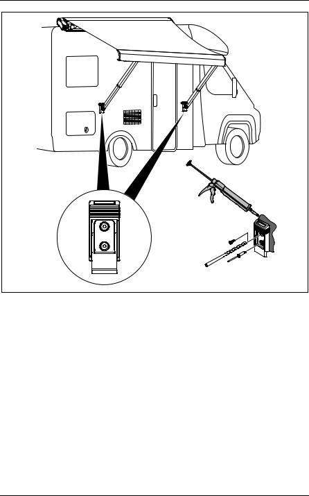
Installing the wall bracket
The wall bracket must be installed if the awning is to be attached to the side of the vehicle when extended.
Select the location of the installation.
Mark where the holes are to be drilled.
At the marked points, drill holes with a diameter of 3 mm from the outside into the external wall (fig. 5, page 4).
Put the upper and lower sections of the wall bracket together.
Clean the outer sides of the lower section and the installation surface in the vehicle.
INOTE
Make sure that no glue gets on to the movable upper section of the wall bracket.
To glue and seal, apply an elastic adhesive, such as Sikaflex®-221 for example, to the back of the wall bracket.
Fasten the wall bracket with drill screws (fig. 5, page 4). or
Rivet the wall bracket in place (fig. 5, page 4).
Installing the crank bracket
Install the wall bracket for the crank at a suitable location inside the vehicle (fig. 6, page 5).
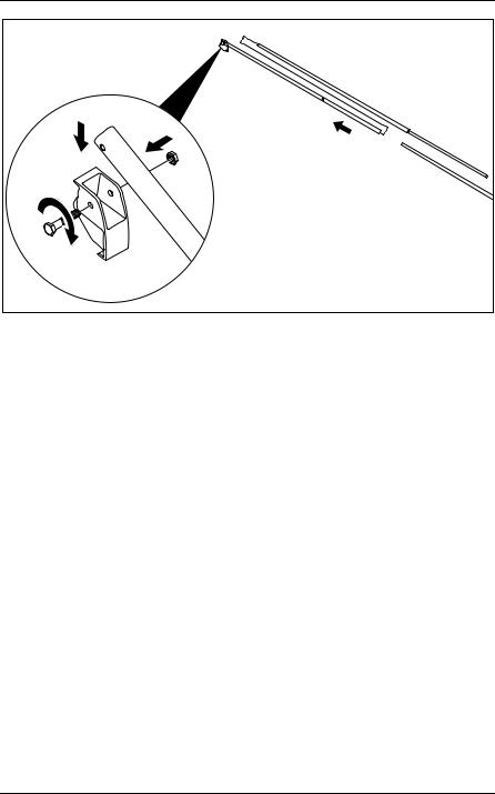
Mounting the tensioning arm
Awnings with a width of 4 m to 5.5 m must be secured using a tensioning arm.
Attach the pre-drilled end of the tensioning arm to the latch for the tensioning arm using the hexagon head bolt and the hexagon nut with clamping part (fig. 7, page 6).
Insert the lower section of the tensioning arm into the upper section (fig. 7, page 6).
14 |
EN |

PR2000, PR2500 |
Disposal |
7 Disposal
Place the packaging material in the appropriate recycling waste bins wherever possible.
M If you wish to finally dispose of the product, ask your local recycling centre or specialist dealer for details about how to do this in accordance with the applicable disposal regulations.
EN |
15 |

PR2000, PR2500
!WARNUNG!
Diese Anleitung muss vor der Installation, dem Einrichten, dem Betrieb und der Wartung gelesen und verstanden werden. Dieses Gerät muss von einer Fachkraft installiert werden. Eine fehlerhafte Installation kann zu schweren Verletzungen führen. Umbauten am Gerät können äußerst gefährlich werden und zu schweren Verletzungen oder zu Geräteschäden führen.
Diese Anleitung muss beim Gerät verbleiben. Der Besitzer muss sie aufmerksam lesen.
Inhaltsverzeichnis
1 Erklärung der Symbole . . . . . . . . . . . . . . . . . . . . . . . . . . . . . . . . . . 17 2 Wichtige Sicherheitsund Einbauhinweise . . . . . . . . . . . . . . . . . . . 18 3 Lieferumfang . . . . . . . . . . . . . . . . . . . . . . . . . . . . . . . . . . . . . . . . . . 19 4 Zubehör . . . . . . . . . . . . . . . . . . . . . . . . . . . . . . . . . . . . . . . . . . . . . . 21 5 Bestimmungsgemäßer Gebrauch . . . . . . . . . . . . . . . . . . . . . . . . . . 21 6 Markise montieren . . . . . . . . . . . . . . . . . . . . . . . . . . . . . . . . . . . . . . 22 7 Entsorgung. . . . . . . . . . . . . . . . . . . . . . . . . . . . . . . . . . . . . . . . . . . . 25
16 |
DE |

PR2000, PR2500 |
Erklärung der Symbole |
1 Erklärung der Symbole
!WARNUNG!
Sicherheitshinweis: Nichtbeachtung kann zu Tod oder schwerer Verletzung führen.
AACHTUNG!
Nichtbeachtung kann zu Materialschäden führen und die Funktion des Produktes beeinträchtigen.
IHINWEIS
Ergänzende Informationen zur Bedienung des Produktes.
Handlung: Dieses Symbol zeigt Ihnen, dass Sie etwas tun müssen. Die erforderlichen Handlungen werden Schritt für Schritt beschrieben.
Dieses Symbol beschreibt das Ergebnis einer Handlung.
Abb. 1 5, Seite 3: Diese Angabe weist Sie auf ein Element in einer Abbildung hin, in diesem Beispiel auf „Position 5 in Abbildung 1 auf Seite 3“.
DE |
17 |

Wichtige Sicherheitsund Einbauhinweise |
PR2000, PR2500 |
2Wichtige Sicherheitsund Einbauhinweise
Beachten Sie die vom Fahrzeughersteller und vom Kfz-Handwerk vorgeschriebenen Sicherheitshinweise und Auflagen!
Der Hersteller übernimmt in folgenden Fällen keine Haftung für Schäden:
Beschädigungen am Produkt durch mechanische Einflüsse und Überspannungen
Veränderungen am Produkt ohne ausdrückliche Genehmigung vom Hersteller
Verwendung für andere als die in der Anleitung beschriebenen Zwecke
! Wenn Sie nicht über ausreichende technische Kenntnisse zum Einbauen von Komponenten in Fahrzeugen verfügen, sollten
Sie sich die Markise von einem Fachmann ans Fahrzeug montieren lassen.WARNUNG!
18 |
DE |

PR2000, PR2500 |
Lieferumfang |
3 Lieferumfang
3.1PR2000
Nr. in |
Markisenbreite |
|
|
|
|
|
|
Abb. 1, |
2,6 m, 3 m, 3,25 m, |
4 m |
Bezeichnung |
Seite 2 |
3,5 m, 3,75 m |
|
|
|
|
|
|
|
|
|
|
1 |
1x |
1x |
Markise |
|
|
|
|
2 |
6x |
6x |
Bohrschraube |
|
|
|
|
3 |
2x |
2x |
Wandhalterung (unterer Teil) |
|
|
|
|
4 |
2x |
2x |
Wandhalterung (oberer Teil) |
|
|
|
|
5 |
1x |
1x |
Kurbelhalterung (unterer Teil) |
|
|
|
|
6 |
– |
– |
Kurbelhalterung (oberer Teil) |
|
|
|
|
7 |
4x |
4x |
Niete |
|
|
|
|
8 |
4x |
4x |
Hering |
|
|
|
|
9 |
1x |
1x |
Kurbel |
|
|
|
|
10 |
– |
1x |
Arretierung für Spannstange |
|
|
|
|
11 |
– |
1x |
Sechskantschraube |
|
|
|
|
12 |
– |
1x |
Spannstange |
|
|
|
|
13 |
– |
1x |
Sechskantmutter mit Klemmteil |
|
|
|
|
DE |
19 |

Lieferumfang |
PR2000, PR2500 |
3.2PR2500
Nr. in |
Markisenbreite |
|
|
|
|
|
|
Abb. 1, |
2,6 m, 3 m, |
4 m, 4,5 m, |
Bezeichnung |
Seite 2 |
3,5 m, 3,75 m |
5 m, 5,5 m |
|
|
|
||
|
|
|
|
1 |
1x |
1x |
Markise |
|
|
|
|
2 |
8x |
8x |
Bohrschraube |
|
|
|
|
3 |
2x |
2x |
Wandhalterung (unterer Teil) |
|
|
|
|
4 |
2x |
2x |
Wandhalterung (oberer Teil) |
|
|
|
|
5 |
1x |
1x |
Kurbelhalterung (unterer Teil) |
|
|
|
|
6 |
1x |
1x |
Kurbelhalterung (oberer Teil) |
|
|
|
|
7 |
4x |
4x |
Niete |
|
|
|
|
8 |
4x |
4x |
Hering |
|
|
|
|
9 |
1x |
1x |
Kurbel |
|
|
|
|
10 |
– |
1x |
Arretierung für Spannstange |
|
|
|
|
11 |
– |
1x |
Sechskantschraube |
|
|
|
|
12 |
– |
1x |
Spannstange |
|
|
|
|
13 |
– |
1x |
Sechskantmutter mit Klemmteil |
|
|
|
|
20 |
DE |
PR2000, PR2500 |
Zubehör |
4 Zubehör
Als Zubehör erhältlich (nicht im Lieferumfang enthalten):
Bezeichnung |
Artikelnummer |
|
|
Dometic Light LK120 |
9106504018 |
LED-Beleuchtung mit Fernbedienung zur Montage an |
|
die Markisenarme |
|
|
|
Tie Down Kit |
9103104000 |
Gurte zum Abspannen der Markise |
|
|
|
Dometic Markisen PR2000 und PR2500 werden über eine fahrzeugspezifische durchgängige Montageschiene angebaut, die nicht im Lieferumfang enthalten ist.
Montageschiene einschließlich Befestigungsmaterial für Fiat Ducato, Citroën Jumper, Peugeot Boxer (mittlere Höhe, Baujahr ab 2006)
Fahrzeuglänge |
Markisenbreite |
|
|
5,41 m |
3,1 m |
|
|
5,99 m |
3,5 m |
|
|
6,36 m |
4,0 m |
|
|
Eine Liste aller erhältlicher Montageschienen finden Sie auf dem Zubehörblatt. Eine aktuelle, vollständige Übersicht der verfügbaren Adapter können Sie bei Ihrem Service-Partner erfragen oder im Internet finden unter www.my-caravanning.de.
Bei Fragen zu Zubehör wenden Sie sich bitte an Ihren Service-Partner.
5 Bestimmungsgemäßer Gebrauch
Die Dometic Markisen PR2000 und PR2500 sind geeignet zum Anbau an Wohnmobile oder Wohnwagen.
Die Markisen dürfen nur im Stand benutzt werden. Bitte beachten Sie die Bedienungsanleitung.
DE |
21 |

Markise montieren |
PR2000, PR2500 |
6 Markise montieren
6.1Benötigtes Montagematerial
Für die Montage der Markise benötigen Sie:
Montageschiene (nicht im Lieferumfang enthalten, muss passend zum Fahrzeug bestellt werden)
Diverses Werkzeug, z. B. Schraubendreher
Geeigneter elastischer Kleber/Dichtmittel wie z. B. Sikaflex®-252
Reiniger, der zur Verwendung mit dem Kleber empfohlen ist
Primer, der zur Verwendung mit dem Kleber empfohlen ist
6.2Hinweise zur Montage
Beachten Sie bei der Montage Folgendes:
! Halten Sie genügend Abstand zu Gegenständen oder anderen Fahrzeugen. Nach dem Ausfahren muss ringsum ein Mindestabstand zu anderen Gegenständen oder Fahrzeugen von
40 cm sein.
Falls die Montageposition nicht durch die Montageschiene fest vorgegeben ist, stellen Sie vor der Installation sicher, dass das
Wohnmobildach die Markise sicher tragen kann. Sonst kann die Markise instabil werden und sich verbiegen oder abbrechen.WARNUNG!
ACHTUNG!
A Falls die fahrzeugspezifische Montageanleitung das Durchschrauben vorsieht, achten Sie darauf, dass die Innenverschraubungen zugänglich sind.
Falls nach dem Einbau der Markise kein ausreichender Freiraum über der Tür verbleibt, muss die Tür während des Einoder Ausfahrens geschlossen bleiben, um einen Kontakt der Tür mit den Armen oder der Frontleiste zu vermeiden.
Der benötigte Freiraum hängt von der Bauart der Tür (Türbreite, Schwenkoder Schiebetür) sowie dem eingestellten Neigungswinkel der Markise ab (Abb. 2, Seite 3).
Leitungen und Einbauschränke im Fahrzeuginnenraum dürfen beim Bohren nicht beschädigt werden.
22 |
DE |

PR2000, PR2500 |
Markise montieren |
HINWEIS
I Weisen Sie den Benutzer des Fahrzeugs darauf hin, dass die Schrauben am Schultergelenk (Abb. 3, Seite 3) nachgezogen werden müssen (siehe Bedienungsanleitung). Die Arme müssen lastfrei sein. Dies muss durch den Service-Partner erfolgen.
6.3Markise montieren
Beachten Sie bei der Montage folgenden allgemeinen Hinweise:
Die Montageschienen werden im Bereich der Schultergelenke an den
Fahrzeugen verschraubt. Zusätzlich werden sie mit Montagekleber
(z. B. Sikaflex®-252 oder ein vergleichbares Produkt) verklebt, um eine gleichmäßige Lasteinleitung zu erhalten und einen optimalen Schutz vor Feuchtigkeit zu erreichen.
Beachten Sie die Hinweise des Dichtmittel-Herstellers.
Jedem fahrzeugspezifischen Montage-Kit liegt eine bebilderte Anleitung bei, die der jeweiligen Montageart angepasst ist. Diese Anleitung muss ergänzend zur Installationsanleitung genau beachtet und eingehalten werden.
Prüfen Sie vor der Montage die Zugänglichkeit der Verschraubungen. Achten Sie darauf, dass beim Bohren keine Leitungen oder Einbauschränke beschädigt werden.
Sollten Sie eine andere Neigungswinkeleinstellung wünschen als ab Werk vorgesehen, wenden Sie sich an Ihren Service-Partner.
Falls Sie später ein Markisenvorzeit mit der Markise verwenden wollen, sollten Sie bei der Auswahl der Markisengröße und Montageposition darauf achten, dass Ausstellfenster und Klappen auch bei montiertem Zelt zugänglich bleiben (Abb. 4, Seite 3).
Reinigen Sie die Klebeflächen auf der Montageschiene und der Wand.
Bereiten Sie die Klebeflächen mit dem Primer vor.
Warten Sie nach dem Kleben, bis der Kleber ausgehärtet ist. Nähere Angaben entnehmen Sie den Informationen des Dichtmittel-Herstellers.
Dichten Sie die Bohrungen sorgfältig ab, damit keine Feuchtigkeit eindringen kann.
Fahren Sie die Markise nicht aus und lassen Sie sie nicht unbeaufsichtigt, solange die Markise noch nicht an der Montageschiene fixiert ist.
DE |
23 |

Markise montieren |
PR2000, PR2500 |
Die Schrauben der Schultergelenke müssen im Rahmen einer regelmäßigen Wartung von einem Service-Partner nachgezogen werden. Weisen Sie die Benutzer des Fahrzeuges hierauf hin.
Montieren Sie die Markise entsprechend den Anweisungen der Bedienungsanleitung, die Ihrer Montageschiene beiliegt.
Wandhalterung montieren
Wenn die Markise im ausgefahrenen Zustand an der Fahrzeugwand befestigt werden soll, muss die Wandhalterung montiert werden.
Legen Sie den Montageort fest.
Zeichnen Sie die Bohrungen vor.
Bohren Sie an den angezeichneten Stellen von außen Löcher mit einem Durchmesser von 3 mm in die Außenwand (Abb. 5, Seite 4).
Stecken Sie das untere und das obere Teil der Wandhalterung zusammen.
Reinigen Sie die Außenseiten des unteren Teils der Wandhalterung und die Montagefläche am Fahrzeug.
IHINWEIS
Stellen Sie sicher, dass kein Kleber an das bewegliche obere Teil der Wandhalterung gerät.
Tragen Sie zum Kleben und Abdichten auf die Rückseite der Wandhalterung einen elastischen Kleber wie z. B. Sikaflex®-221 auf.
Verschrauben Sie die Wandhalterung mit Bohrschrauben (Abb. 5, Seite 4).
oder
Vernieten Sie die Wandhalterung (Abb. 5, Seite 4).
Kurbelhalterung montieren
Montieren Sie die Wandhalterung für die Kurbel an einer geeigneten Stelle innerhalb des Fahrzeugs (Abb. 6, Seite 5).
24 |
DE |

PR2000, PR2500 |
Entsorgung |
Spannstange montieren
Markisen mit einer Breite von 4 m bis 5,5 m müssen mit einer Spannstange gesichert werden.
Befestigen Sie das vorgebohrte Ende der Spannstange mit der Sechskantschraube und der Sechskantmutter mit Klemmteil an der Arretierung für Spannstange (Abb. 7, Seite 6).
Setzen Sie den unteren Teil der Spannstange in den oberen Teil der Spannstange ein (Abb. 7, Seite 6).
7 Entsorgung
Geben Sie das Verpackungsmaterial möglichst in den entsprechenden Recycling-Müll.
Mmieren Sie sich bitte beim nächsten Recyclingcenter oder bei Ihrem Fachhändler über die zutreffenden Entsorgungsvorschriften.Wenn Sie das Produkt endgültig außer Betrieb nehmen, infor-
DE |
25 |

PR2000, PR2500
!AVERTISSEMENT !
Ce manuel doit être lu et compris avant l'installation, la mise en place, le fonctionnement et la maintenance. Cet appareil doit être installé par un technicien agréé. Une installation erronée peut entraîner de graves blessures. Des modifications de l'appareil peuvent s'avérer extrêmement dangereuses et provoquer de graves blessures ou des dommages de l'appareil.
Ce manuel doit rester à proximité de l'appareil. Le propriétaire doit le lire attentivement.
Sommaire
1 Explication des symboles. . . . . . . . . . . . . . . . . . . . . . . . . . . . . . . . . 27 2 Consignes de sécurité et instructions de montage importantes . . . 28 3 Contenu de la livraison . . . . . . . . . . . . . . . . . . . . . . . . . . . . . . . . . . 29 4 Accessoires . . . . . . . . . . . . . . . . . . . . . . . . . . . . . . . . . . . . . . . . . . . 31 5 Usage conforme. . . . . . . . . . . . . . . . . . . . . . . . . . . . . . . . . . . . . . . . 31 6 Montage du store extérieur . . . . . . . . . . . . . . . . . . . . . . . . . . . . . . . 32 7 Retraitement . . . . . . . . . . . . . . . . . . . . . . . . . . . . . . . . . . . . . . . . . . 35
26 |
FR |

PR2000, PR2500 |
Explication des symboles |
1 Explication des symboles
!AVERTISSEMENT !
Consigne de sécurité : le non-respect de ces consignes peut entraîner la mort ou de graves blessures.
AAVIS !
Le non-respect de ces consignes peut entraîner des dommages matériels et des dysfonctionnements du produit.
IREMARQUE
Informations complémentaires sur l'utilisation du produit.
Manipulation : ce symbole vous indique une action à effectuer. Les manipulations à effectuer sont décrites étape par étape.
Ce symbole décrit le résultat d’une manipulation.
Fig. 1 5, page 3 : cette information renvoie à un élément figurant sur une illustration, dans cet exemple à la « position 5 de l'illustration 1 à la page 3 ».
FR |
27 |

Consignes de sécurité et instructions de montage importantes |
PR2000, PR2500 |
2Consignes de sécurité et instructions de montage importantes
Respectez les consignes de sécurité et autres prescriptions imposées par le fabricant du véhicule et par les professionnels de l’automobile !
Le fabricant décline toute responsabilité pour des dommages dans les cas suivants :
des influences mécaniques et des surtensions ayant endommagé le matériel
des modifications apportées au produit sans autorisation explicite de la part du fabricant
une utilisation différente de celle décrite dans la notice
! Si vos connaissances techniques en matière d'installation d'éléments dans un véhicule sont insuffisantes, nous vous recommandons de faire installer l'auvent par un spécialiste.AVERTISSEMENT !
28 |
FR |

PR2000, PR2500 |
Contenu de la livraison |
3 Contenu de la livraison
3.1PR2000
N° dans |
Largeur du store extérieur |
|
|
|
|
|
|
fig. 1, |
2,6 m, 3 m, 3,25 m, |
4 m |
Désignation |
page 2 |
3,5 m, 3,75 m |
|
|
|
|
|
|
|
|
|
|
1 |
1 |
1 |
Store extérieur |
|
|
|
|
2 |
6 |
6 |
Vis perceuse |
|
|
|
|
3 |
2 |
2 |
Support mural (partie inférieure) |
|
|
|
|
4 |
2 |
2 |
Support mural (partie supérieure) |
|
|
|
|
5 |
1 |
1 |
Support de manivelle (partie |
|
|
|
inférieure) |
|
|
|
|
6 |
– |
– |
Support de manivelle (partie |
|
|
|
supérieure) |
|
|
|
|
7 |
4 |
4 |
Rivet |
|
|
|
|
8 |
4 |
4 |
Sardine |
|
|
|
|
9 |
1 |
1 |
Manivelle |
|
|
|
|
10 |
– |
1 |
Blocage pour barre de tension |
|
|
|
|
11 |
– |
1 |
Vis six pans |
|
|
|
|
12 |
– |
1 |
Barre de tension |
|
|
|
|
13 |
– |
1 |
Écrou six pans avec pièce de serrage |
|
|
|
|
FR |
29 |

Contenu de la livraison |
PR2000, PR2500 |
3.2PR2500
N° dans |
Largeur du store extérieur |
|
|
|
|
|
|
fig. 1, |
2,6 m, 3 m, |
4 m, 4,5 m, |
Désignation |
page 2 |
|
||
3,5 m, 3,75 m |
5 m, 5,5 m |
|
|
|
|
||
|
|
|
|
1 |
1 |
1 |
Store extérieur |
|
|
|
|
2 |
8 |
8 |
Vis perceuse |
|
|
|
|
3 |
2 |
2 |
Support mural (partie inférieure) |
|
|
|
|
4 |
2 |
2 |
Support mural (partie supérieure) |
|
|
|
|
5 |
1 |
1 |
Support de manivelle (partie |
|
|
|
inférieure) |
|
|
|
|
6 |
1 |
1 |
Support de manivelle (partie |
|
|
|
supérieure) |
|
|
|
|
7 |
4 |
4 |
Rivet |
|
|
|
|
8 |
4 |
4 |
Sardine |
|
|
|
|
9 |
1 |
1 |
Manivelle |
|
|
|
|
10 |
– |
1 |
Blocage pour barre de serrage |
|
|
|
|
11 |
– |
1 |
Vis six pans |
|
|
|
|
12 |
– |
1 |
Barre de serrage |
|
|
|
|
13 |
– |
1 |
Écrou six pans avec pièce de |
|
|
|
serrage |
|
|
|
|
30 |
FR |
 Loading...