


Owner’s and Safety Manual (pages 2-25)
Manuel d’emploi et de sécurité (pages 26-49)
Manual de empleo y de seguridad (página 50-73)
Warning:
Read and understand this Owner’s and Safety Manual. Always follow safety precautions in the Owner’s and Safety Manual. Improper use can cause serious injury! The engine exhaust from this product contains chemicals known to the State of California to cause cancer, birth defects or other reproductive harm. Keep this Owner’s and Safety Manual!
Attention:
Suivez toujours les conseils de sécurité du présent manuel d’emploi et de sécurité. Une utilisation incorrecte de la débroussailleuse peut entraîner des blessures graves! Conservez avec soin ce manuel. Les gaz d’échappement émis par ce produit contiennent des produits chimiques connus par l’Etat de Californie pour provoquer le cancer, des défauts de naissance ou autres dommages de reproduction. Lisez et comprenez ce manuel.
Advertencia:
Observe siempre las instrucciones de seguridad contenidas en el manual. Lea y compenétrese con el contenido del manual. El uso inadecuado de la desbrozadoras puede causar lesiones de gravedad. Los gases de escape del motor de este producto contienen sustancias químicas conocidas en el Estado de California como causantes de cáncer, defectos genéticos y otros problemas relacionados con la reproducción. Conserve este manual cuidadosamente.
MS-3310
MS-4010
MS-4510
1

Thank you for choosing a DOLMAR product!
We trust that you will be a satisfied customer. By choosing a DOLMAR you have chosen one of the most advanced brushcutters. We are the world´s oldest manufacturer of gasoline powered saws (1927), giving us almost 7 decades of experience with two-stroke-engine powered tools.
The MS-3310, MS-4010 and MS-4510 brushcutters combine the benefits of state-of-the-art technology with ergonomic design, and are professional machines intended for all types of use.
The high-efficiency engine is the heart of the brushcutter, and has been completely redesigned. Special cylinder geometry, computerized control times, and maintenance-free electronic ignition give high performance with low fuel consumption.
The drive shaft is designed for continuous heavy-duty use, with 9 bearings and a tough centrifugal clutch. The fuel tank is positioned forward, for the right c to make long jobs easier and less fatiguing.
Some of the other technical features of your DOLMAR brushcutter are:
-Precision-tuned vibration damping
Four conical hollow absorption elements, between the engine and the main tube and between the engine and the tank unit with handles, reduce felt vibration to a minimum, for comfortable, untiring long-term working.
-Multi-function handle
All important controls are located on the right handle for ease of operation.
-Easy cutting-tool change
A new locking system developed by DOLMAR allows you to lock the cutting tool for simple, safe blade changing.
-High-efficiency noise reduction
The completely encapsulated engine and the resonator-chamber intake muffler make this brushcutter remarkably quiet.
The following industrial property rights apply: US 512606, EP 0438611, EP 0696414, GBM 9106194, GBM 9412925.
To ensure your own safety and to get the maximum performance out of your DOLMAR brushcutter, we urge you to
read this instruction manual carefully before putting the brushcutter into operation and strictly observe all of the safety regulations! Failure to do so can result in serious injury to the operator and/or bystanders!
Packing
Your DOLMAR brushcutter comes in a cardboard box to protect it from shipping damage.
Cardboard is a raw material. We encourage you to re-use the box or recycle it (waste paper).
RE Y
Table of contents |
Page |
Packing ...................................................................... |
2 |
Delivery inventory ..................................................... |
3 |
Explanation of symbols ........................................... |
3 |
SAFETY PRECAUTIONS |
|
General precautions .............................................. |
4 |
Personal protective equipment .............................. |
4 |
Handling fuels / Refuelling ..................................... |
5 |
Putting into operation .......................................... |
5-6 |
Kickback................................................................. |
6 |
Working behavior / Method of working .................. |
7 |
Applications for cutting tools .................................. |
7 |
Transport ............................................................... |
7 |
Storage .................................................................. |
7 |
Maintenance .......................................................... |
8 |
First Aid .................................................................. |
8 |
Technical data ........................................................... |
9 |
Components .............................................................. |
9 |
PUTTING INTO OPERATION |
|
Mounting the tube handle .................................... |
10 |
Installing the cutter guard ............................... |
10-11 |
Installing the steel bush cutter, |
|
8-tooth eddy blade or star blade ..................... |
11-12 |
Installing the trimmer head .................................. |
12 |
Installing the line cutter ........................................ |
12 |
Installing the metal cutter guard and |
|
chisel type saw blade .......................................... |
13 |
The gear box ........................................................ |
13 |
Fuel mixture ......................................................... |
14 |
Storage of fuel ..................................................... |
14 |
Refuelling ............................................................. |
14 |
Putting on the harness ......................................... |
15 |
Balancing the brushcutter .................................... |
15 |
Starting the engine............................................... |
16 |
Carburetor adjustment ......................................... |
17 |
REPAIR AND MAINTENANCE WORK |
|
Sharpening of cutting tools .................................. |
18 |
Trimmer head ...................................................... |
19 |
Starter cable replacement .............................. |
19-20 |
Cleaning the air filter ............................................ |
20 |
Replacing/cleaning the spark arrestor screen ..... |
21 |
Inspecting and replacing the spark plug .............. |
21 |
Checking the muffler bolts ................................... |
21 |
Suction head in the fuel tank ............................... |
22 |
Muffler guard (for USA only) ................................ |
22 |
Information about the gear box............................ |
22 |
Shutting down procedure and storage ................ |
22 |
Service, spare parts and guarantee ................. |
23-24 |
Troubleshooting...................................................... |
24 |
Extract from the spare part list ............................. |
25 |
Notes ........................................................................ |
25 |
Service centres (see enclosure) |
|
2

Delivery inventory
3
2
1
4
1.Brushcutter
2.Shoulder Strap*
3.Cutter*
4.Guard*
5.Tool Protection* (not shown)
6.Servicing Tool (not shown)
7.Owner’s and Safety Manual (not shown)
*The parts as shown differ from model to model, and may look different from this illustration.
If one of these parts is missing when you unpack the brushcutter, contact your dealer!
Explanation of symbols
You will notice the following symbols on the brushcutter and in the Owner’s and Safety Manual.
max. |
max. |
10.000 1/min |
11.500 1/min |
Read the Owner’s and Safety manual and |
Carburetor adjustment |
follow all warnings and safety instructions! |
|
Particular care and caution! |
Choke |
Forbidden! |
Start engine |
|
|
Wear protective gloves! |
Stop engine! |
STOP |
|
Wear safety shoes! |
|
Wear protective helmet, face, eye and |
No smoking! |
|
|
hearing protection (eye protection must |
|
comply with ANSI Z87-1)! |
|
The distance between the machine and |
No open flame! |
|
|
bystanders shall be at least 50 feet! |
|
DANGER: |
Fuel and oil mixture |
|
|
Beware of thrown objects! |
|
CAUTION: Kickback! |
First aid |
|
|
(blade thrust) |
|
RE Y |
|
Maximum tool rpm |
Recycling |
|
Direction of blade rotation
3
SAFETY PRECAUTIONS
General precautions
To ensure correct operation, the user has to read this instruction manual to make himself familiar with the handling of the brushcutter. Insufficiently informed users will risk danger to themselves as well as others due to improper handling (1).
-It is recommended only to lend the brushcutter to people who have experience with brushcutters. When lending the brushcutter to someone else, give him this Instruction Manual as well.
-First-time users should ask their dealer for basic instructions, or contact a forestry school. To familiarize yourself with the basic handling of gasoline-powered brushcutting, start out with trimming jobs before moving up to sawing.
-Children and persons under 18 years must not be allowed to operate the brushcutter with metal cutting tools (such as saw blades, steel bush cutter, star blades etc.). Exceptions may be made for persons over 16 for training purposes under the supervision of a qualified trainer.
-Always use brushcutters with the utmost care and attention.
-Operate the brushcutter only if you are in good physical condition. Perform all work calmly and carefully. The user must accept liability for others.
-Never use the brushcutter after consumption of alcohol, drugs or medication (2).
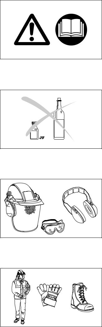
Personal protective equipment
-The clothing worn should be functional and appropriate, i.e. it should be tight-fitting but not cause hindrance. Do not wear either jewellery or clothing which could become entangled with bushes or shrubs.
-In order to avoid head-, eye-, handor foot injuries as well as to protect your hearing, the following protective equipment and protective clothing must be used during operation of the brushcutter:
-It is recommended to wear a protective helmet; it is imperative when working in forests. The protective helmet (1) should be checked at regular intervals for damage and must be replaced after 5 years at the latest. Use only approved protective helmets. If you have long hair, always wear a hairnet!
-The face shield (2) of the protective helmut protects against flying sawdust, wood chips or stone chippings. During operation of the brushcutter always wear goggles or a visor to prevent eye injuries.
-Wear adequate noise protection equipment to avoid hearing impairement ( ear muffs (3), ear plugs etc.). Octave brand analysis upon request.
-The forestry safety jacket (4) is equipped with special red coloured shoulder parts. The arms and neck should always be protected by clothing.
-The protective trousers (5) are made from a nylon fabric with 22 layers and protects against cuts. We strongly recommend its use. In any case, it is essential that a long pair of trousers made of tough material be worn during operation of the brushcutter. Do not wear short pants.
-Protective gloves (6) made of thick leather are part of the prescribed equipment and must always be worn during operation of the brushcutter.
-Safety shoes or boots (7) fitted with anti-skid sole, steel toe caps and leg protection must always be used. Safety shoes equipped with a protective layer give protection against cuts and ensure a secure footing. Do not wear sandals or go barefoot.
1
2
1
3
2
3
4 
7
5 6
4
4
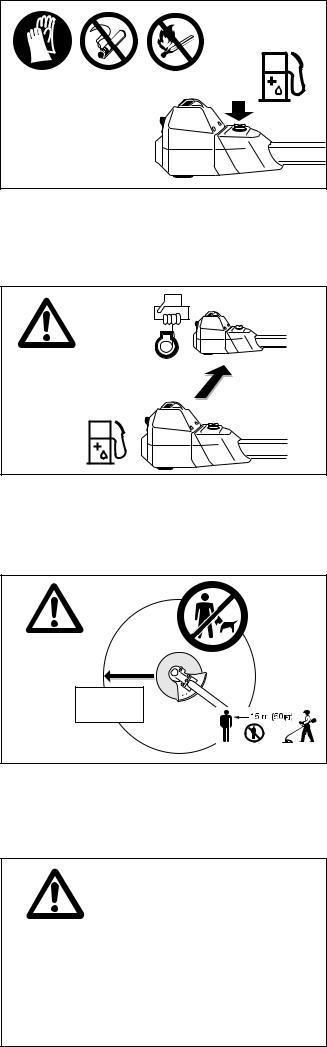
Handling fuels / Refuelling
-Stop the engine before refuelling.
-Keep away from open flame or sparks and do not smoke while refuelling or mixing fuel (5).
-Let the engine cool down before refuelling.
-Fuel may contain substances similar to solvents. Eyes and skin should not come in contact with mineral oil products. Always wear protective gloves when refuelling
(5). Frequently clean and change protective clothes. Do not breathe in fuel vapors. Inhalation of fuel vapours can be hazardous to your health.
-Before refuelling the brushcutter make sure it is in a stabile position.
-Do not spill fuel or oil. When you have spilt fuel or oil immediately clean the brushcutter. Fuel should not come in contact with clothes. If your clothes come in contact with fuel, change them at once.
-Ensure that no fuel ooze into the soil (environmental protection). Use an appropriate base.
-Refuelling is not allowed in closed rooms. Fuel vapors will accumulate near the floor (explosion hazard).
-Carefully tighten the locking screw of the fuel tank and inspect the fuel cap at regular intervals.
-Change the place before starting the engine at least 10 feet (3 meters) from the place of refuelling (6).
-Fuel cannot be stored for an unlimited period of time. Buy only as much as will be consumed in the near future.
-Use only approved and marked containers for the transport and storage of fuel. Ensure children have no access to fuel.
Putting into operation
-Do not work alone. Another person must be nearby in case of emergencies (within shouting distance).
-Children and other persons must remain more than 50 feet (15 meters) from the working area. Keep an eye out for animals as well (7).
-Before use always check that the brushcutter is safe for operation:
Make sure the cutting tool is securely installed. The throttle must automatically return to the off position when released, and the throttle lever lock must work properly. The cutting tool must not turn during idling. The handles should be clean and dry. The on/off switch must function properly. The guard must be undamaged and securely installed in the correct position. Otherwise you are in danger of injury!
-Start the brushcutter only in accordance with the instructions. Do not use any other methods for starting the engine (8)!
-Use this brushcutter and its cutting tools only for the uses they are intended for as specified in the documentation.
-Never use, for example, wire or wire-rope which can break off and become a dangerous projectile. Use only flexible, non-metallic line recommended in this manual.
-Start the brushcutter only after complete assembly and inspection. Operation of the device is only permitted after all the appropriate accessories are attached!
-The cutting tool must be equipped with its appropriate guard. Never run the cutter without this guard!
-The cutting tool must not turn during idling. If necessary adjust the idling speed.
5
10 feet
(3 meters)
6
360o
50 feet
(15 meters)
7
8
5
-Before starting, make sure that the cutting tool has no contact with hard objects such as branches, stones etc.
-The engine must be switched off immediately if there are any noticeable changes in the behaviour of the equipment.
-Should the cutting tool hit stones or other hard objects, immediately switch off the engine and inspect the cutting tool.
-Inspect the cutting tool at freqvent intervals for damage (detect hairline cracks by means of tapping - noise test). Hairline cracks can occur in the region of the base of the teeth (9) after long use. Damaged cutting tools and cutting tools with hairline cracks must not be used any longer under any circumstances.
-Operate the brushcutter only with the shoulder strap attached, which is to be suitably adjusted before putting the brushcutter into operation (10). It is essential to adjust the shoulder strap according to the user’s size to prevent fatigue during use. Never hold the cutter with one hand during use.
-When working with the brushcutter always hold it with both hands (10). Keep cutting attachment below waist level. Keep proper footing and balance at all times.
-Operate the brushcutter in such a manner as to avoid inhalation of the exhaust gases. Do not start or operate the brushcutter in closed rooms (risk of gas poisoning). Carbon monoxide is an odorless gas; breathing exhaust fumes can kill. Work only in well-ventilated places.
-When taking a break or leaving the brushcutter unattended, turn off the engine (11), make sure the cutting attachment has stopped and set the brushcutter down in such a way that there is no risk of injury to yourself or others.
-Never put the hot brushcutter onto dry grass or onto any combustible materials.
-Shut off the engine during transport or when moving on to a new location (11).
-Never operate the engine with a faulty exhaust muffler. If the spark arrestor screen is damaged, replace it immediately. The use of the brushcutter with a damaged spark arrestor can cause bushfires!
Kickback (Blade Thrust)
When operating the brushcutter, uncontrolled kickback may occur.
This particularly the case when cutting in the area between 12 and 2 (12).
Never start a cut in this area when cutting hard objects such as brush, bushes etc.
If you do this, the brushcutter will be thrown to one side at high speed and with great force. High risk of injury! Never start a cut in the area between 12 and 2 (Fig. 12). Kickback prevention (13):
-To avoid kickbacks, observe the following:
-Always watch what you´re doing! Be careful when continuing cuts started previously.
-The cutting tool must be turning at full speed before starting cuts.
-There is a high risk of injury in the area between 12 and 2, especially when using metal cutting blades.
-Cuts in the areas between 11 and 12 and between 2 and 5 should be performed only by trained operators and at their own risk.
-Easy, low-kickback cutting is possible in the area between 8 and 11.
9
10
STOP
|
STOP |
|
● Breaks |
|
● Transport |
|
● Refuelling |
|
● Maintenance |
11 |
● Tool Replacement |
CAUTION:
Kickback!
12
12 
CAUTION: 9 3 Kickback! 


6
13
6

Working behavior / Method of working
-Use the brushcutter only in good light and visibility. During the winter season beware of slippery or wet areas, ice and snow (risk of slipping). Always ensure a safe footing.
-Never cut above your shoulder height.
-Never stand on a ladder and run the brushcutter.
-Never climb up into trees to perform cutting operations with the brushcutter.
-Never work on unstable surfaces.
-Make sure the cutting area is free of foreign objects such as stones and metal items. Foreign particles can rebound (danger of injury, 14), damage the cutting tool and cause dangerous kickbacks.
-Before commencing cutting, the cutting tool must have reached full working speed.
Applications for cutting tools
Employ only the correct cutting tool for the job in hand (15)! Do not use tools for jobs they are not designed for.
2-line -/ 4-line trimmer head:
Exclusively for cutting along walls, fences, grass edges, trees, posts etc. (supplementing the lawn mower).
8-tooth eddy blade, 4-tooth star blade, steel bush cutter:
For cutting thicker materials like weeds, tall grass, bushes, shrubs, mixed growth, thickets, etc. with stems up to 2 cm (3/4") thick. Perform this cutting work by swinging the brush cutter evenly in half-circles from left to right (similar to a scythe) (16).
Chisel type saw blade:
For forestry cleanup work and for harvesting small trees with trunks up to 6" (15 cm) thick (17). Apply even pressure when cutting.
Transport
-When transporting the equipment or moving to another working location, the brushcutter must be switched off in order to avoid unintentionally starting the cutting tool.
-Never carry and transport the brushcutter when the cutting tool is in operation!
-The tool protection included with the equipment must always be used if the brushcutter is transported over longer distances.
-Ensure that the brushcutter is safely secured so that no fuel can run out before transporting it in a vehicle. Empty the fuel tank before transporting the brushcutter.
-Before shipping the brushcutter, completely empty the fuel tank.
Storage
-The brushcutter must be safely stored in a dry room. Use the tool protection for metal cutting tools. Keep the brushcutter out of reach of children.
-If the brushcutter is stored for a long period of time, it should be given a thorough maintenance check and a complete inspection at an authorized DOLMAR service centre.
-If the brushcutter is stored for a long period of time, the fuel tank should be completely emptied and the carburetor run dry. Fuels may only be stored for a limited period of time and could cause deposits to form in the tank or in the carburetor.
-Fuel remains in reserve canisters should be used for other engines or disposed of.
DANGER:
Beware thrown objects!
14
2-line -/ 4-line trimmer head |
8-tooth eddy blade |
4-tooth star blade |
steel bush cutter |
15 |
chisel type saw blade |
|
16
Max ø 6"
(15 cm)
17
7

Maintenance
-Always make sure the brushcutter is in good working order before using it. This includes in particular the cutting tool, guard, harness and fuel system (check for leaks). Particular attention must be paid to the cutting blades, which must be correctly sharpened.
CAUTION: Metal cutting tools must be sharpened only at an authorized service centre!
A tool which has been improperly sharpened can cause unbalance and thus considerable danger of injury. Apart from this, the equipment may be damaged due to vibrations.
-When changing the cutting tool, cleaning the brushcutter and the cutting tool etc., it is essential to switch off the engine and pull the spark plug cap.
-Replace cracked, bent, warped, damaged or dull cutting tools immediately. Never straighten or weld damaged cutting tools.
-Operate the brushcutter with as little noise and pollution as possible. In particular check the correct setting of the carburetor.
-Clean the brushcutter at regular intervals and check that all screws and nuts are well tightened.
-Never service or store the brushcutter near open flames (18)!
-Always store the brushcutter in a locked storage area, with the fuel tank completely empty and the carburetor run dry. Keep the brushcutter out of reach of children.
Observe the accident prevention instructions issued by the relevant trade associations and insurance companies. Do not make any modifications to the brushcutter - you will only be putting your own safety at risk!
The performance of maintenance or repair work by the user is limited to those activities described in this instruction manual. All other work must be done by the DOLMAR customer service (19).
Use only original DOLMAR spares and accessories.
The use of non-DOLMAR spares, accessories, or cutting tools increases the risk of accident. DOLMAR will not accept any liability for accidents or damage caused by the use of non-approved cutting tools and fixing devices of cutting tools, or accessories.
First Aid
A first-aid kit should always be nearby as a precaution in the event of an accident.
Immediately replace any items taken from the first aid kit.
When calling for help, give the following information:
-Place of accident
-What happened
-Number of persons injured
-Nature of injuries
-Your name
NOTE
Individuals with poor circulation who are exposed to excessive vibration may experience injury to blood vessels or the nervous system.
Vibration may cause the following symptoms to occur in the fingers, hands or wrists: ”Falling asleep” (numbness), tingling, pain, stabbing sensation, alteration of skin colour or of the skin. If any of these symptoms occur, see a physician!
18
19
20
21
SERVICE
8
|
Technical Data |
|
|
|
|
|
|
|
|
MS-3310 |
MS-4010 |
MS-4510 |
|||
|
|
|
|||||
|
|
|
|
|
|
||
|
Displacement |
cu. in |
2.0 (33 cm3) |
2.4 (39 cm3) |
2.7 (45 cm3) |
||
|
Bore |
inch |
1.46 (37 mm) |
1.57 (40 mm) |
1.69 (43 mm) |
||
|
Stroke |
inch |
1.22 (31 mm) |
1.22 (31 mm) |
1.22 (31 mm) |
||
|
Rated capacity per ISO 8893 |
kW |
1.6 |
1.8 |
2.3 |
||
|
Operating speed |
rpm |
9,000 |
9,000 |
9,000 |
||
|
Max. engine speed with |
|
|
|
|
|
|
|
one-part metal cutting tool 1) |
rpm |
13,500 |
13,500 |
13,500 |
||
|
Maximum speed of the tool spindle with |
|
|
|
|
|
|
|
one-part metal cutting tool 1) |
rpm |
10,400 |
10,400 |
10,400 |
||
|
Idling speed |
rpm |
2,500 |
2,500 |
2,500 |
||
|
Clutch engagement speed |
rpm |
3,500 |
3,500 |
3,500 |
||
|
Sound pressure level at the operators ear 3) |
dB (A) |
98 a) / 101 b) |
98 a) |
/ 102 b) |
99 a) |
/ 102 b) |
|
Sound pressure level at the bystander’s position (50 ft) 3) dB (A) |
75 a) / 77 b) |
76 a) |
/ 78 b) |
76 a) |
/ 78 b) |
|
|
Carburetor (diaphragm-carburetor) |
Type |
WALBRO WT-225 A |
WALBRO WT-225 A |
WALBRO WT-225 A |
||
|
Ignition system |
Type |
Transistor ignition |
Transistor ignition |
Transistor ignition |
||
|
Spark plug |
Type |
CHAMPION RCJ6Y |
CHAMPION RCJ6Y |
CHAMPION RCJ6Y |
||
|
Electrode gap |
inch |
.020-.030 (0.5-0.8 mm) |
.020-.030 (0.5-0.8 mm) |
.020-.030 (0.5-0.8 mm) |
||
|
Fuel consumption per ISO 8893 2) |
kg/h |
0.72 |
0.81 |
1.03 |
||
|
Specific consumption per ISO 8893 2) |
g/kWh |
450 |
450 |
450 |
||
|
Fuel tank capacity |
oz. |
31.7 (0.9 l) |
31.7 (0.9 l) |
31.7 (0.9 l) |
||
|
Mixture ratio (Fuel/2-stroke oil) |
|
|
|
|
|
|
|
- when using DOLMAR oil |
|
50 : 1 |
50 : 1 |
50 : 1 |
||
|
- when using DOLMAR HP 100-oil |
|
100 : 1 |
100 : 1 |
100 : 1 |
||
|
- when using other oils |
|
40 : 1 |
40 : 1 |
40 : 1 |
||
|
Gear ratio |
|
1 : 1.3 |
1 : 1.3 |
1 : 1.3 |
||
|
Dimensions, assembled, |
|
|
|
|
|
|
|
length / width / height |
inch |
71.1 / 26.8 / 8.9 |
71.1 / 26.8 / 8.9 |
71.1 / 26.8 / 8.9 |
||
|
Total weight with plastic guard |
|
|
|
|
|
|
|
(without cutting tool) |
lbs |
17.42 (7.9 kg) |
17.42 (7.9 kg) |
17.42 (7.9 kg) |
||
|
|
|
|
|
|
|
|
1)The maximum rated speed of the trimmer head is not exceeded when using a DOLMAR trimmer head.
2)At max. power. 3) According to ANSI B 175.3. a) With one-part metal cutting tool. b) With 2-line nylon cutting head.
|
|
1 |
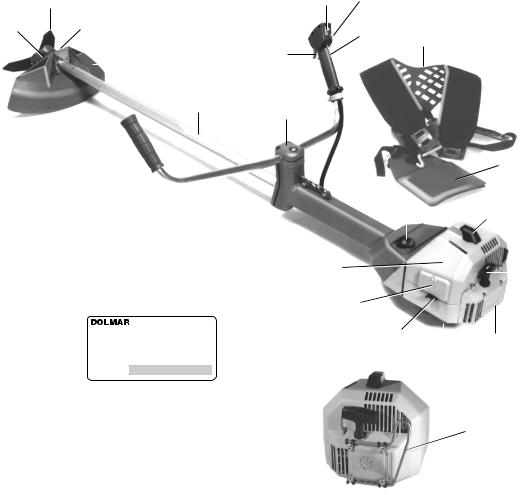
Components |
2 |
3 |
1Cutting tool
2Gear box
3Locking bolt
4Guard (Cutter guard)
5Main tube
6Handle tube
7Throttle (throttle trigger)
8Short-circuit switch (Start/Stop)
9Stop knob for halfway throttle
10Safety locking button (throttle trigger lockout)
11Bowden cable guide
12Tube handle holder
13Hole bar
14Tank cap
15Spark plug
16 Starter grip
17 Fan housing
18 Type plate
19Choke lever
20Air filter (behind air filter cover)
21Cover
22Harness
23Hip protection pad
24Muffler guard (for USA only)
8 9
10 22
7
5 12
|
|
|
|
|
|
|
|
|
|
|
|
11 |
|
23 |
|||||
|
|
|
|
|
|
|
|
|
|
|
|
|
|||||||
|
|
|
|
|
|
|
|
|
|
|
|
13 |
|
|
|
|
|
|
|
|
|
|
|
|
|
|
|
|
|
|
|
|
|
|
|
||||
6 |
|
|
|
|
|
|
|
|
|
|
|||||||||
|
|
|
14 |
15 |
|
||||||||||||||
|
|
|
|
|
|
|
|
|
|
|
|
||||||||
21 |
20 |
|
|
|
|
|
16 |
||||||||||||
|
|
|
|
|
|||||||||||||||
|
|
||||||||||||||||||
|
|
|
|
|
|
|
|
|
|
|
|
|
|
|
|
|
|||
MS-4510 |
|
|
|
|
|
|
|
|
|
||||||||||
|
|
|
|
|
|
|
|
|
|||||||||||
9806 123456 |
|
|
Serial number |
19 |
|
|
17 |
|
|||||||||||
|
|
|
|
|
|
|
|
|
|
|
|||||||||
|
|
|
|
|
|
|
|
|
|
|
|||||||||
|
|
|
|
|
|
|
|
Year of manufacture |
|
|
|||||||||
|
|
|
|
|
|
|
|
|
|
|
|
18 |
|
|
|||||
|
|
|
|
|
|
|
|
|
|
|
|
|
|
|
|
|
|||
24
9

PUTTING INTO OPERATION
|
STOP |
CAUTION: |
When working on the brushcutter always be absolutely certain to switch off the engine, pull the |
|
spark plug cap and wear protective gloves! |
IMPORTANT: |
Do not start the brushcutter until fully assembled and inspected! |
Mounting the tube handle
The handle tube (A/1) comes fixed parallel to the main tube.
1
A 2
-Use the universal wrench to loosen the locking screw (A/2) (counter-clockwise) until it is possible to turn the tube handle through 900.
900
450
B |
2 |
C |
|
||
|
|
|
-After the tube handle has engaged in the 90° position, tighten the locking screw (B/2) a little, while still leaving it loose enough to allow further adjustment of the tube handle according to your size (See "Balancing the brushcutter").
-Move the handle tube into a position approximately 45° with respect to the main tube (C).
Installing the cutter guard
IMPORTANT: Safety regulations and your own safety make it imperative to use the right cutter guard with a given cutting tool! Use only the combinations shown here, and when switching to a different cutting tool always change the cutter guard as well!
WARNING: Use only the cutting tools shown here! It is not permitted to use other cutting tools as this can increase danger of accidents and cause damage to the equipment!
Tool/guard combinations for the MS-3310, MS-4010 and MS-4510
Cutting tool |
Cutter guard |
Steel bush cutter, part no. 385 224 130 |
|
Outside diameter 300 mm (12"), arbour 20 mm |
Part no. 010 341 612 |
8-tooth eddy blade, part no. 385 224 180 |
|
Outside diameter 255 mm (10"), arbour 20 mm |
Part no. 010 341 612 |
Star blade, part no. 385 224 140 |
|
Outside diameter 255 mm (10"), arbour 20 mm |
Part no. 010 341 612 |
2-line trimmer head, part no. 385 224 501 |
|
4-line trimmer head, part no. 385 224 541 |
* |
|
|
Cutting range 400 mm (16"). Use only 2.4 mm (.095") replacement cutting line. |
part no. 010 341 612 |
15 m part no. 369 224 070 |
* Install line cutter (knife), |
120 m part no. 369 224 072 |
part no. 957 341 010! |
Chisel type saw blade, part no. 385 224 160 |
part no. 010 341 100 (for 225 mm) |
Outside diameter 225 mm (9"), arbour 20 mm |
Impressed: 385 341 045 |
Chisel type saw blade, part no. 385 224 170 |
part no. 010 341 030 (for 200 mm) |
Outside diameter 200 mm (8"), arbour 20 mm |
Impressed: 385 341 030 |
10
CAUTION:
The cutter guard supplied must always be fitted in the right position, to ensure your personal safety and to meet legal accident prevention regulations.
Never use the brushcutter without a cutter guard installed!
A |
1 |
B |
C |
The position of the mounting plate (C/1) will depend on the type of cutting tool in use (trimmer head or metal blade). The position of the mounting plate determines whether the guard will be positioned higher or lower.
When using a trimmer (line) head apply the mounting position as shown in fig. A.
The mounting position as shown in fig. B is required for use with the following tools:
•Star blade
•8-tooth eddy blade
•Steel bush cutter
Always fix the metal cutter guard if a chisel type saw blade is used (refer to page 13).
2
D
-To install, lay the guard on the holder on the gear box. Place the mounting plate (D/2) on the guard in the appropriate position (A or B) for the type of cutting tool in use and tighten the installing screws with the Allen key as shown.
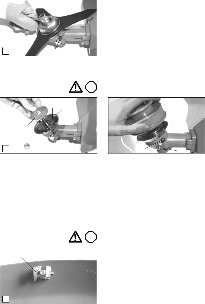
Installing the steel bush cutter, 8-tooth eddy blade or star blade
STOP
Always switch off the engine and disconnect the spark plug cap before mounting cutting tools! Wear protective gloves!
5 6
3
E 4
When using the blade cutting tools mentioned on the preceding page, install the cutter guard with the mounting plate in position B (see “Installing the cutter guard”).
-Unscrew the locknut (E/3) from the shaft by turning it clockwise.
Note: The locknut is provided with a left-hand thread!
-Remove the pressure disk (E/4) and the locking disk (E/5).
-Tighten the winding guard (E/6) with the three screws provided.
-Put the locking disk (E/5) back on (make sure it is in the right position).
4
3
8
F 7
- Put on the cutting tool (F/8) and finally the pressure disk (F/4) as shown in the picture.
Important! The picture shows the steel bush cutter. When installing the 8-tooth eddy blade make sure to observe the direction of rotation arrows on blade and on cutter guard!
-Put on the sliding cup (F/7) and screw the lock nut (F/3) manually onto the shaft.
The sliding cup is included in the accessories!
Important! The locknut (F/3) has a plastic insert protection. For safety reasons, this nut must be replaced immediately if it becomes loose. It must be replaced in any event after 10 tool changes at the latest. (Order no. 385 228 041)
11
|
|
|
|
G |
10 9 |
|
|
|
-Press the locking button (G/9) and hold it down, while using the combination wrench to turn the shaft counter-clockwise until the locking button engages and locks the shaft.
-Now tighten the locknut counter-clockwise using the combination wrench.
-To unlock the locked shaft press the release button (G/ 10). The locking button (G/9) will trip (if necessary turn the cutting tool slightly).
-Check to make sure the cutting tool can turn freely.
Use the shaft lock in the same way when dismounting the cutting tool.
Installing the trimmer head
Always switch off the engine and
disconnect the spark plug cap STOP before mounting the trimmer head!
5
6
4
H |
|
|
1 |
|
When using the trimmer head install the cutter guard with the mounting plate in position A (see “Installing the cutter guard”). Always install the line cutter (see below, “Installing the line cutter”)!
-Unscrew the locknut (H/1) from the shaft by turning it clockwise.
Note: The locknut has a left-hand thread!
-Place the pressure disk (H/4) on the shaft as shown.
Installing the line cutter |
STOP |
11
J
2-line trimmer head shown
I |
10 |
9 |
|
|
-If necessary, install the winding guard (H/6) (three screws). To do so, first remove the locking disk (H/5) (note its position as installed).
-Screw the trimmer head onto the shaft by turning it counter-clockwise.
-Press the locking button (I/9) and hold it down while turning the trimmer head counter-clockwise until the locking button engages, locking the shaft.
-Now tighten the trimmer head by hand.
-Press the release button (I/10) to unlock the shaft. The locking button (I/9) will jump out (it may be necessary to turn the trimmer head slightly).
-Check to make sure the trimmer head can turn freely.
The line cutter and its mounting screw are included in the accessory pack.
-The picture shows the line cutter (J/11) mounted on the cutter guard with the mounting screw.
Note:
If you adjust the length of the trimmer line (see page 19), the line cutter will automatically cut the lines to identical length during operation.
Caution:
Always turn off the engine before adjusting the line length!
12
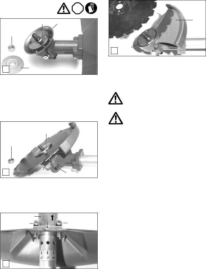
Installing the metal cutter guard and chisel type saw blade
Always switch off the engine and disconnect the spark plug cap
before mounting cutting tools! STOP Wear protective gloves!
5 6
3
K 4
Always install the metal cutter guard when installing the chisel type saw blade!
-Unscrew the locknut (K/3) from the shaft by turning it clockwise.
Note:The locknut has left-hand thread!
-Remove the pressure disk (K/4) and the locking disk (K/5).
4
3
M |
10 |
9 |
The gear box
13 |
15 |
|
14 |
||
14 |
N
12
L5
-If the winding guard is on, remove it (K/6) by unscrewing the three screws.
-Screw the steel cutter guard (L/12) on tightly.
-Put the locking disk (L/5) on.
-Put on the cutting tool and finally the pressure disk (M/4) as shown in the picture.
Important! When installing the chisel type saw blade make sure that the direction of rotation arrows on saw blade and on cutter guard are pointing in the same direction!
Important: The locknut (K/3) has a plastic insert protection. For safety reasons, this nut must be replaced immediately if it becomes loose. It must be replaced in any event after 10 tool changes at the latest (order no. 385 228 041)!
-Screw the locknut (M/3) onto the shaft by hand.
-Press the locking button (M/9) and hold it down while using the combination wrench to turn the shaft counter-clockwise until the locking button engages and locks the shaft.
-Now tighten the locknut counter-clockwise using the combination wrench.
-Press the release button (M/10) to unlock the shaft. The locking button (M/9) will jump out (if necessary turn the saw blade slightly).
-Check to make sure the saw blade can turn freely.
In order to achieve easier operation along slopes and fitches, it is possible to swivel the gear box (N/13) from the normal position to either side by approximately 45 degrees.
Adjustment:
-Loosen the two screws (N/14).
-Loosen screw (N/15) enough to turn the gear box in the direction indicated by the arrow until the three boreholes are visible at the main tube.
-Turn the gear box in the direction indicated until the position of the screw (N/15) matches up with the borehole.
- Move the gear box back again and tighten the first screw (N/15) and subsequently the remaining two screws (N/14) by the same amount.
13
Fuel mixture
|
Gasoline |
|
|
|
40:1 |
|
50:1 |
|
100:1 |
|
||||||||||||
|
|
|
|
|
|
|
|
other oil |
DOLMAR oil |
DOLMAR oil |
||||||||||||
|
|
|
|
|
|
|
|
|
|
|
|
|
|
|
|
|
|
|
|
|
||
|
|
|
|
|
|
|
|
|
|
|
|
|
|
|
|
|
|
|
|
|
|
|
|
|
|
|
|
|
|
|
|
|
|
|
|
|
|
|
|
|
|
|
|
||
|
|
|
|
|
|
|
|
|
|
|
|
|
|
|
|
|
|
|
|
|
|
|
|
|
|
|
|
|
|
|
|
|
|
|
|
|
|
|
|
|
|
|
|
||
|
|
|
|
|
|
+ |
|
OIL |
|
|
OIL |
|
HP 100 |
|||||||||
|
|
|
|
|
|
|
|
|
|
|
|
50:1 |
|
|||||||||
|
|
|
|
|
|
|
|
|
|
|
|
|
||||||||||
|
|
|
|
|
|
|
|
|
|
|
|
|
|
|
|
|
|
|
|
|||
|
|
|
|
|
|
|
|
|
|
|
|
|
|
|
|
|
|
|
|
|
|
|
|
|
|
|
|
|
|
|
|
|
|
|
|
|
DOLMAR |
|
|
|
|
|
|
||
|
|
|
|
|
|
|
|
|
|
|
|
|
|
|
|
|
|
|
|
|
|
|
|
|
|
|
|
|
|
|
|
|
|
|
|
|
|
|
|
|
|
|
|
|
|
|
|
|
|
|
|
|
|
|
|
|
|
|
|
|
|
|
|
|
|
|
|
|
1.0 |
Us-gal. |
(3.7 |
l) |
|
3.2 floz.(94 cm3) |
2.5 floz.(75 cm3) |
1.3 floz.(38 cm3) |
|||||||||||||||
2.5 |
Us-gal. |
(9.4 |
l) |
|
8.0 floz.(236 cm3) |
6.4 floz.(189 cm3) |
3.2 floz.(94 cm3) |
|||||||||||||||
5.0 |
Us-gal. (18.9 |
l) |
16.0 floz.(473 cm3) |
12.8 floz.(378 cm3) |
6.4 floz.(189 cm3) |
|||||||||||||||||
|
|
|
|
|
|
|
|
|
|
|
|
|
|
|
|
|
|
|
|
|
|
|
The brushcutter is powered by a high-performance two-stroke engine. The engine runs on a mixture of gasoline and two-stroke engine oil.
The engine was designed for regular lead-free gasoline with an octane number of at least 91 ROZ. If this is not available, higher-octane gasoline may be used. This will not damage the engine, but may impair engine performance.
A similar situation will arise from the use of leaded fuel. To obtain optimum engine operation and to protect your health and the environment, only unleaded fuel should be used! Gasoline which contens alcohol should not used in DOLMAR products.
For lubricating the engine use a two-stroke engine oil (quality grade: API-TC), which is added to the fuel. The engine has been designed for use of DOLMAR HP 100 high-performance two-stroke engine oil and a mixture ratio of only 100:1 to protect the environment. In addition, a long service life and reliable operation with a minimum emission of exhaust gases are ensured.
DOLMAR HP 100 high-performance two-stroke engine oil is available in the following sizes:
0.5l part no. 980 008 109
DOLMAR high-performance two-stroke engine oil is available in two different sizes:
1 l |
part no. 980 008 107 |
100 ml |
part no. 980 008 106 |
In case DOLMAR high-performance two-stroke engine oil is not available, it is urgently recommended to use a mixture ratio of 40:1 with other two-stroke engine oils, as otherwise optimum operation of the engine cannot be guaranteed.
Preparation of the correct mixture ratio:
50:1 When using DOLMAR high-performance two-stroke oil, i.e. 50 parts gasoline /1 part oil.
100:1 when using DOLMAR HP 100 high-performance twostroke engine oil, i. e. mix 100 parts gasoline with 1 part oil.
40:1 When using other brands, i.e. 40 parts gasoline / 1 part oil.
Note:
When preparing the fuel mixture, always first mix the entire oil quantity with half of the gasoline, and then add the rest of the gasoline. Shake the mixture well before putting in the fuel tank.
It is not wise to add more oil to the mixture than specified, even if this may seem safer for the engine. More oil only leads to increased combustion residues, which not only pollute the environment, but are also bad for the cylinder exhaust channel, muffler and the spark arrester screen. Furthermore fuel consumption will increase and performance will fall.
AVOID SKIN AND EYE CONTACT!
Utmost care is required when handling fuel. Fuel may contain substances similar to solvents. Refuel either in a well ventilated room or outdoors. Do not inhale fuel vapours. Fuel vapours are poisonous and can be hazardous to your health. Avoid eye and skin contact with fuels and mineral oils. Mineral oil products degrease your skin. If your skin comes in contact with these substances repeatedly and for an extended period of time, it will desiccate. Various skin deseases may result. In addition, allergic reactions are known to occur. Eyes can be irritated by contact with oil. If oil comes into your eyes, immediately wash them with clear water.
If your eyes are still irritated, see a doctor immediately!
Storage of Fuel
Fuels have a limited storage life. Fuel and fuel mixtures age. Therefore fuel and fuel mixtures, which have been stored for too long, can cause starting problems. Purchase only that amount of fuel, which will be consumed over the next few months.
Store fuel safely in a dry place in approved containers only.
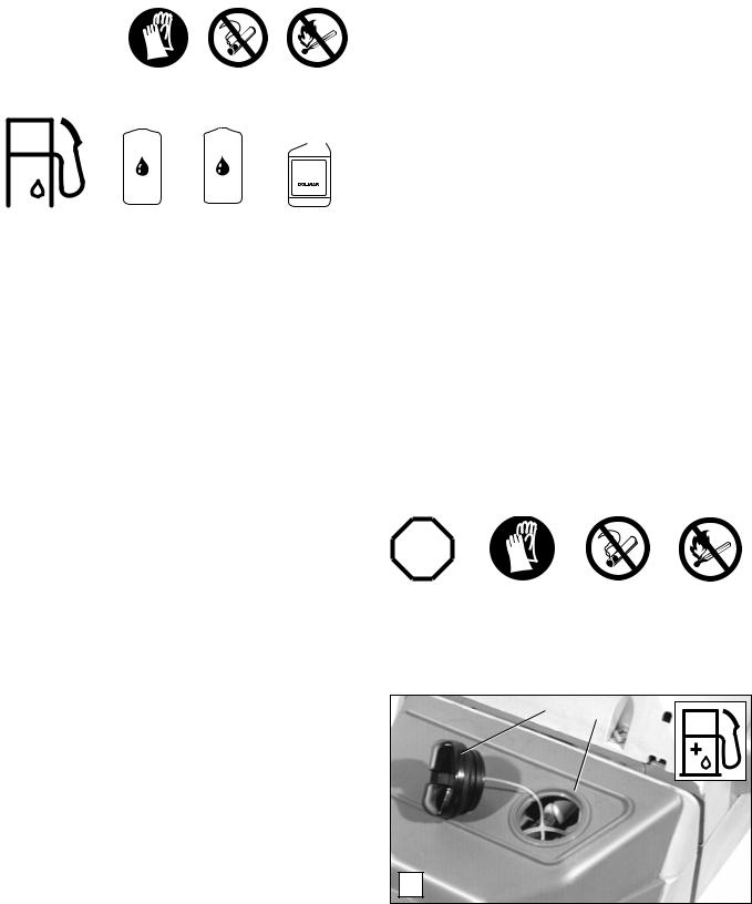
Refuelling
STOP
FOLLOW THE SAFETY PRECAUTIONS!
Be careful and cautious when handling fuels.
The engine must be switched off!
2 1
B
-Thoroughly clean around the tank cap (B/1) so that no dirt can enter the fuel tank.
-Before refuelling the brushcutter make sure it is in a stabile position.
-Unscrew the tank cap (B/2) and carefully fill in the fuel mixture up to the lower edge of the filler neck. Fill the tank carefully, making sure not to spill any fuel.
-Tightly screw on the plug.
Clean screw plug and tank after refuelling.
14

Putting on the harness
2
A 1
-Place the harness over both shoulders so that the hip pad (A/1) is located on your right hand side.
-Adjust the harness until the chest plate (A/2) fits across your chest.
B
-Adjust the height of the hip pad means by of the chest strap until the fixing hook is located about one hand’s width above the hip bone.
-To open the harness detach the chest plates.
The harness and the brushcutter can then easily and quickly be removed.
Balancing the brushcutter
3
C
-Fill the fuel tank.
-Attach the brushcutter to the fixing hook (C/3) located on the waist pad.
-5 boreholes are provided for the correct personal balancing of the brushcutter .
4
D
-To remove the brushcutter, first depress the lock (D/4) and then detatchthe brushcutter from the fixing hook.
E
-The ground clearance will depend on the kind of cutting tool selected.
-When using the trimmer head or steel bush cutter, the trimmer head or sliding cup should touch the ground lightly without the user having to hold the unit.
-In difficult terrain or when using the steel bush cutter or 8- tooth eddy blades the brushcutter should balance about 12" (30 cm) above the ground without the user having to hold the unit.
5
F
-Adjust the handles according to the working condition and then always retighten the locking screw (F/5).
15

Putting into operation
Observe accident-prevention regulations!
Do not start the brushcutter until fully assembled and inspected!
Starting the engine
-Move at least 10 feet (3 meters) away from where you filled the fuel tank.
-Make sure you have a good footing, and lay the brushcutter on the ground in such a way that the cutting tool is not touching the ground or anything else.
Cold start
6
10
7
8
G
-Move the switch (G/6) in the direction of the arrow.
-To set the half-throttle catch, press the throttle (G/8) with the throttle trigger lockout (G/7) pressed and then press the catch (G/10). Release the throttle (G/8) and then the throttle trigger lockout (G/7).
 9
9
H
- Turn the choke lever (H/9) downwards to choke the engine.
I
-Hold the brushcutter frimly down with one hand, as illustrated above.
-Pull the starter handle out slowly until resistance is noticed, then pull the starter handle out fully with a quick and forceful movement.
-Do not pull out the whole starter cable to its full extent and do not let the starter handle jump back, but let it slowly automatically rewind itself.
-Repeat starting procedure until ignition is achieved.
-Turn the choke lever (H/9) back up and pull the starter cable again until the engine starts.
16
6
8
J
-After the engine has started, press the throttle (J/8) all the way in and release immediately. This will disengage the half-throttle position.
-Run the engine for approximately 1 minute at a moderate speed before commencing work.
Warm start
Similar to a cold start but without the choke.
Turning off the engine
Move switch (J/6) to the position STOP .
Carburetor adjustment
Important information:
The carburetor of this tool is fitted with limiter caps which restrict the range of adjustment and prevents over-rich mixture settings. This ensures providing good engine power and efficient fuel consumption.
Before installing the limiter caps, the manufacturer performs the „Basic Adjustment” procedure.
Maximum power is achieved throughcarburetor adjustment. It requires a warm engine and a clean air filter and should preferably be performed by an expert.
The carburetor comes factory-set for the atmospheric pressure at sea-level. At other elevations and during the run-in phase with a new engine it may be necessary to adjust the carburetor.
A tachometer (order no. 950 233 210) is a must for accurate carburetor adjustment.
Before adjusting the carburetor, install the cutting tool you are going to use and warm up the engine by running it 3-5 minutes.
For a precise adjustment the following steps are to be performed:
1. |
Check adjustment |
STOP |
2. |
Start engine |
|
3. Set idling speed
4.Adjust speed
5.Check idling speed
6.Check acceleration
7.Check max. speed or output
8.Repeat adjustment procedure starting with step 3, until idling speed, max. speed and acceleration are reached with the adjustment made.
L H
A
Adjustment instructions (step 1) STOP
-Before initial operation make sure that the adjusting screws (H and L) have not been set in all the way. Limiter caps do not protect the engine from leaning.
-Turn the two adjusting screws (H and L) counter-clock-
wise as far as they will go.
- Start the engine and let it warm up (step 2).
S
H
B
Set idling speed (step 3)
-If the cutting tool turns when the engine is idling, screw the throttle-valve stop screw (S) until the cutting tool stops turning. The idling speed should be now 2,300-2,500 rpm/ min.
Adjust speed (step 4)
-Set the engine speed to 13,000-13,500 RPM by adjusting the main jet screw (H). Screwing it in makes the fuel/air mixture leaner (less fuel, more air) and increases the engine speed.
Caution:
Engine speeds above 13,500 RPM reduce engine life!
L
C
Check idling speed (step 5)
-Now check the idle speed. It should be 2,300-2,500 RPM (the cutting tool should not turn). If necessary, adjust the idle speed with the idle jet screw (L). Turning it in increases the speed, and turning it out decreases it.
Check acceleration (step 6)
-This is the time it takes for the engine to go from idle speed to maximum speed when you press the throttle hard.
-If acceleration is too slow, turn the idle screw (L) out about 1/8 turn.
17
REPAIR AND MAINTENANCE WORK
CAUTION: |
Before doing any work on the brushcutter, always switch off the motor and pull |
||
|
|
|
|
STOP |
the plug cap off the spark plug. Always wear protective gloves! |
||
CAUTION: Start the brushcutter only after complete assembly and inspection!
Sharpening of cutting tools
Caution: Wear always gloves during sharpening!
1 |
|
|
|
2 |
|
|
|||
|
D |
3 |
Note: The cutting tools below should be sharpened only at a qualified workshop! Manual resharpening will result in an imbalance of the cutting tool, causing vibrations and engine damage.
•Steel bush cutter (D/1)
•Star blade (D/2)
•8-tooth eddy blade (D/3)
Expert sharpening can be obtained from a DOLMAR service station.
Note: To increase the working life the steel bush cutter and the star blade may be turned over once until their second cutting sides are blunt.
After it has been sharpened and resharpened several times the chisel type saw blade must be sharpened and balanced at a qualified workshop.
Caution:
For to safety reasons, never try to straighten or weld a damaged cutting tool!
20o-25o
F 5o
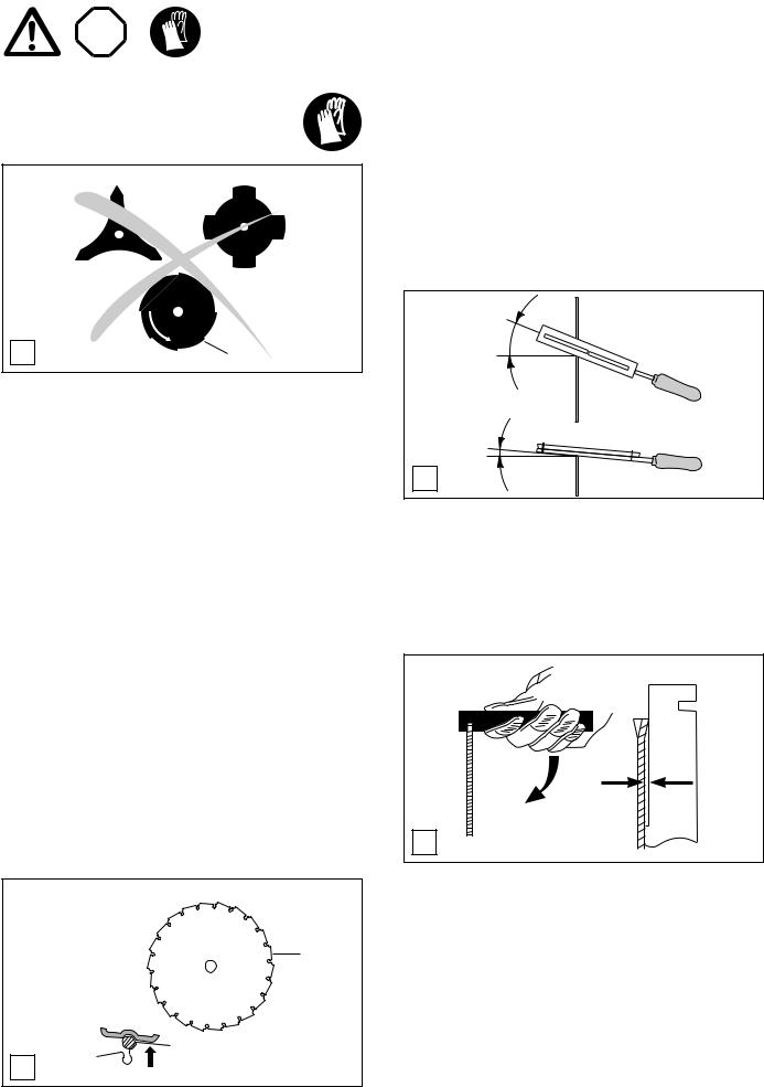
Always maintain a sharpening angle of 20-25 degrees (F).
For this purpose please observe that the markings on the top surface of the file should follow in a parallel direction to the saw blade.
The inclination should be approximately 5 degrees (F).
Chisel type saw blade
When sharpening the chisel type saw blade (E/4) with a round file take care to sharpen all tooth recesses evenly.
The damage of only one tooth requires equal sharpening or refiling of all other teeth.
If teeth have broken off the chisel type saw blade, it has to be replaced.
Uneven sharpening will result in strong vibration due to an imbalance which will cause damage to the cutter as well as generating vibration in the handles.
Use only a special 5.5 mm dia. round file for saw blades with support (part no. 953 009 000) to sharpen the chisel type saw blade. Other round files are not suitable.
When hand-sharpening a mounted saw blade, make sure the brushcutter is properly supported.
4
E
File only the tooth face. The file support should rest on the back of the tooth as illustrated above (arrow).
Setting the teeth
A
.040"
B (1mm)
G
Should the saw blade jam during cutting, inspect the tooth setting.
The setting should be .040" (1 mm).
To correct the setting of the saw blade teeth use the saw blade adjusting tool which is available as an accessory (Part no. 953 385 010).
The existing tooth setting of the saw blade must be strictly maintained!
Push down on the adjusting tool as shown (A).
To inspect the tooth setting, hold the adjusting tool against the saw blade. The tooth should touch against the offset part of the adjusting tool (B).
18
Trimmer head
Lengthening the line
2 1
A |
3 |
Schematic
Starter cable replacement
STOP
|
5 |
|
||||
|
6 |
|
|
|
|
|
|
|
|
||||
|
|
|
|
|
|
|
|
|
|
|
|
|
|
B |
|
|
|
|
|
4 |
|
|
|
|
|
||
|
||||||
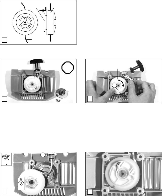
-Unscrew the ventilator housing.
-Screw out the center screw (B/4).
-Remove the guide disk (B/5) complete with the starter ratchet and the brake spring.
-Remove the pawl spring (B/6).
-Hold the housing (A/1) firmly and pull the housing cover (A/2) out against the spring pressure in the direction of the arrow (figure) until it is possible to turn the cover (A/2) counter-clockwise.
-Stop pulling out on the cover (A/2) and turn it counter-clockwise until it snaps back in.
-Pull the line ends (A/3) out as far as they will go. Repeat this procedure until you have about 6" (15 cm) of line available.
A detailed description of this adjustment is included with the trimmer head.
8
7
C
-Pull out the starter handle and starter cable to length of about 12" (30 cm).
-Hold the starter cable drum and pull out the starter cable using a screw driver or similar tool.
-Let the drum slowly turn backwards (in the direction of the arrow) with the starter cable in the appropriate slot (C/7) until the tension in the spring has been released.
-Remove the drum (C/8).
-If starter cable has split or frayed, remove it from the drum.
-Lubricate the center shaft of the starter cable drum with a multipurpose grease (Part no. 944 360 000) before commencing re-assembly.
9
11
10
D
-Push the starter cable through the guide hole (D/9) and then feed the cable through the opening in the drum and tie a knot as shown above.
-Press the knotted end of the starter cable (D/10) into the appropriate slot in the drum.
-Feed the other cable end through the handle and secure with the knot shown in (D/11).
-Wind the cable onto the drum for about 3 1/4 turns. Pay attention to the correct direction of rotation (counterclockwise when assembled).
12
E
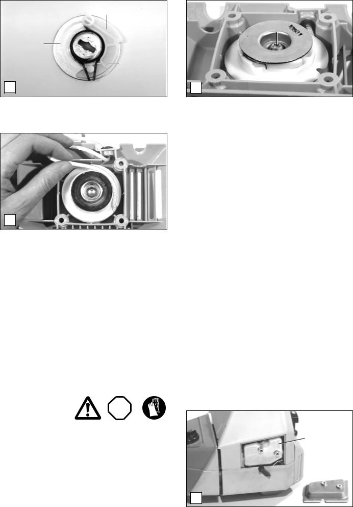
-Put the starter cable drum into the housing and check to make sure the return spring is hooked in the correct position by turning it slightly counter-clockwise.
-Insert the pawl spring (E/12) into the starter cable drum as shown.
19
13
5
14
F
-Lubricate the guide disk (F/5) with a mulitpurpose grease and install the pawl (F/13) and the brake spring (F/14) as illustrated above.
H
Instructions for maintenance
4
5 
6
 13
13
G
-Install the guide disk (G/5) along with the pawl and brake spring into the starter cable drum in such a manner that the pawl spring (G/6) is pressed against the pawl (G/13).
-Turn the guide disk (G/5) so that the shaft guide is located in the slot of the guide disk.
-Screw down the center screw (G/4) to hold the assembly in place.
-Pull the starter cable out of the drum, then insert it into the appropriate slot in the drum and turn the drum, together with the starter cable counter-clockwise for 1 turn. Release the drum and let the spring tension wind up the cable.
-Repeat the above procedure until the starter handle has reached its correct starting location on the ventilator housing assembly.
-Reassemble the ventilator housing.
Do not do any maintenance or servicing work not described in this Instruction Manual. All such work may be done only by a DOLMAR service station.
After refuelling the brushcutter 50 times, it should be given a thorough maintenance check and a complete inspection at a DOLMAR service centre.
Daily maintenance
Perfom the following work daily after use:
-Clean the outside of the brushcutter and inspect for damage.
-Clean the air filter (see below). Under dusty working conditions the air filter must be cleaned more often.
-Check the cutting tool for damage and make sure it is tight.
-Check to make sure that there is sufficient difference between the idle and engagement speed so that the cutting tool does not turn when the engine is idling. If necessary, reduce the idle speed (see page 17). If the cutting tool still turns during idling, take the brushcutter to a service center.
-Check the function of the safetylocking button, the short-circuiting switch and of the throttle lever (see page 16).
Cleaning the air filter |
STOP |
-Remove the air filter cover (I/15). Close the choke lever (I/16) to prevent the entry of dust particles into the carburetor.
-Remove the air filter (I/17) and clean it with a soft brush.
Caution:
To prevent eye injuries, do not blow out dirt particles.
-Very dirty filters can be cleaned out using regular dishwashing liquid in lukewarm water.
-In case of strong pollution clean more often (several times a day) because only a clean filter ensures full engine power.
-Before reinstalling the air filter check the choke valve for dirt particles, and if necessary clean it out with a brush.
-Carefully dry the air filter and reinstall it.
17
15
16
I
Important: If the air filter is damaged replace it immediately! Torn-off fabric pieces and large dirt particles can destroy the engine.
20
Replacing/cleaning the |
STOP |
spark arrestor screen |
5
J
Weekly maintenance |
|
|
Inspecting and replacing |
STOP |
|
the spark plug |
||
|
CAUTION:
NEVER touch the spark plug or spark plug cap while the engine is running (high voltage).
Never do maintenance work with the engine running!
A hot engine can cause severe burns. Wear protective gloves!
18
19
15
K
The spark plug must be replaced if the insulator is damaged or if the electrodes are severely eroded or dirty or oily.
-Pull the spark plug cap (K/18) off the plug. Use only the combination wrench supplied with the brushcutter to remove the spark plug.
Note: Replace only with CHAMPION RCJ-6Y, BOSCH WSR 6F or NGK BPMR 7A spark plugs!
The spark arrestor screen should be checked and cleaned regularly.
-Remove the filter cover (see "Checking the muffler bolts").
-Loosen the 2 screws (J/5) and remove the spark arrestor screen.
-Clean the spark arrestor screen with a soft brush.
NOTE: Do not use sharp or pointed objects for screen cleaning. Damaged or misformed screen wires may result.
IMPORTANT: If the spark arrestor screen is damaged replace it immediately!
-Reassembly the spark arrestor screen and tighten the screws.
.020" - .030"
(0.5 - 0.8 mm)
L
Electrode gap
The electrode gap must be .020" - .030" (0.5 - 0.8 mm).
Checking the ignition spark
-Remove the spark plug. With the spark plug cable on, hold the plug against the cylinder (but not near the spark plug hole!) using insulated pliers.
-Turn the on/off switch to “I” (on).
-Pull the starter cable hard.
A spark should be visible at the electrode gap.
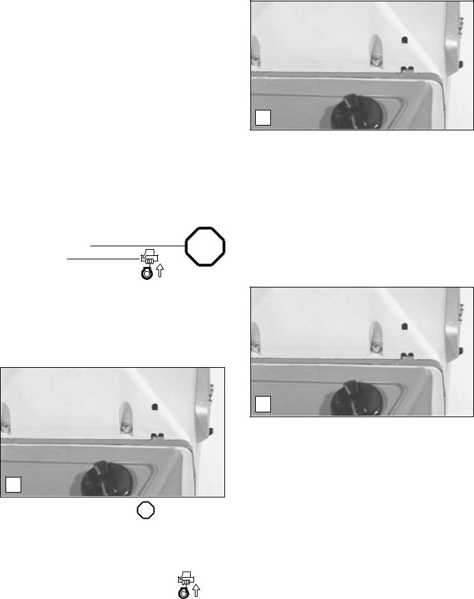
Checking the muffler |
STOP |
|
|
|
|
bolts |
|
|
|
|
|
|
|
|
|
|
|
Caution: |
|
|
|
|
|
|
|
|
|
|
|
Do not tighten the muffler bolts while the engine is hot! |
|
|
|
|
|
- Remove plug connector (K/18) and unscrew and remove |
20 |
||||
the filter cover (K/15). |
|
|
|
|
|
- Loosen the four fixing bolts (K/19) of the cover and remove |
|
|
|
|
|
it. |
|
|
|
|
|
- Check the muffler bolts (M/20) for tightness using the Allen |
|
|
|
|
|
|
M |
|
|
||
key. If loose, tighten manually. Do not over-tighten. |
|
|
|
||
|
|
|
|
||
|
|
|
|
|
|
21
Periodic maintenance
Suction head in the fuel tank
STOP
21
N
Muffler guard |
STOP |
23
22
O
Information about the gear box
24
P
Shutting down procedure and storage
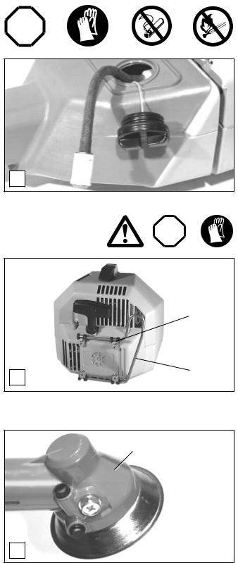
The felt filter (N/21) of the suction head is used to filter the fuel taken in by the carburetor.
A periodical visual inspection of the felt filter should be conducted. For this purpose open the tank cap, and use a wire hook to pull out the suction head through the tank opening. If the filter has hardened or is dirty or clogged, replace it (see "Excerpt from the spare-parts list").
Insufficient fuel supply can result in the admissible maximum speed being exceeded. It is therefore important to replace the felt filter at least every three months to ensure a good fuel supply to the carburetor.
Check if the muffler guard (O/22) is in good condition. A bent, broken or missing muffler guard can cause bush fires especially during dry weather conditions.
Replace a non-functional muffler immediately!
Also check the four clamp rings (O/23) before using the brushcutter. Replace damaged clamp rings immediately! The correct mounting and positioning of the muffler is essential to guarantee protection against a possible fire hazard from the engine exhaust.
The gear box (P/24) is provided with a permanant lubrication and consequently does not need any maintenance.
However, if large quantities of grease are leaking from the gear box, consult a DOLMAR service station.
Servicing and maintenance
We recommend that a comprehensive maintenance and inspection be performed at regular intervals.
Any maintenance or adjustment work not described in this manual may be performed only by a DOLMAR service station.
If you are not planning to use the brushcutter for a period in excess of 6 weeks, it is recommended to observe the following instructions:
•Perform the servicing operations as described on pages 18 to 24.
•Empty the fuel tank and run the engine until the carburetor is dry. Fuels have only a short storage life and can cause sedimentary deposits in the fuel tank or carburetor.
•Remaining fuel in canisters should be used for other engines, or properly disposed of.
•Clean and lightly lubricate metallic cutting tools.
•Store the brushcutter in a dry place only.
•The next time you use the brushcutter, purchase new fuel and prepare the two-stroke mixture as specified.
22

Instructions for periodic maintenance
To ensure long life, prevent damage and ensure the full functioning of the safety features the following maintenance must be performed regularly. Guarantee claims can be recognized only if this work is performed regularly and properly. Failure to perform the prescribed maintenance work can lead to accidents!
|
|
|
Page |
|
|
|
|
General |
Engine assembly |
Visual inspection for damage, loose attachment |
20-22 |
|
|
and fuel tank sealing |
|
|
|
|
|
After each refuelling |
Throttle lever |
Functional check |
16 |
|
Safety lock button |
Functional check |
16 |
|
STOP-switch |
Functional check |
16 |
|
|
|
|
Daily |
Air filter |
Clean |
20 |
|
Cutting tool |
Check for damage and sharpness |
18 |
|
Idle speed |
Check (cutting tool must not move) |
17 |
|
|
|
|
Weekly |
Spark plug |
Inspection, replace if necessary |
21 |
|
Muffler |
Clean and tighten bolts |
21 |
|
|
|
|
Quarterly |
Suction head |
Replace |
22 |
|
Fuel tank |
Clean |
|
|
|
|
|
Shutting down |
Fuel tank |
Empty |
|
procedure |
Carburetor |
Run empty |
|
|
|
|
|
Service, spare parts and guarantee
Maintenance and repair
The maintenance and repair modern brushcutters and safety-related components and assemblies requires qualified technical training and a workshop equipped with special tools and testing devices.
We therefore recommend that you consult a DOLMAR service centre for all work not described in this instruction manual.
The DOLMAR service centres have all the necessary equipment and skilled and experienced personnel, who can work out costeffective solutions and advise you in all matters.
Please contact your nearest service centre (list enclosed).
Spare parts
Reliable long-term operation, as well as the safety of your brushcutter, depend among other things on the quality of the spare parts used. Use only original DOLMAR parts, marked 

Only original spare parts and accessories guarantee the highest quality in material, dimensions, functioning and safety.
Original spare parts and accessories can be obtained from your local dealer. He will also have the spare part lists to determine the required spare part numbers, and will be constantly informed about the latest improvements and spare part innovations.
Please bear in mind that if parts other than original DOLMAR spare parts are used, this will automatically invalidate the DOLMAR product guarantee.
We will furthermore not accept any liability damages arising from the use of non-DOLMAR spare parts.
23
 Loading...