


21 - 202 AUTOMATIC TRANSMISSION 42RLE - ELECTDRICA
AUTOMATIC TRANSMISSION 42RLE
DIAGNOSTICS
TABLE OF CONTENTS
page |
page |
AUTOMATIC TRANSMISSION 42RLE - ELECTRICAL DIAGNOSTICS
DIAGNOSIS AND TESTING
P0122-TPS/APP CIRCUIT LOW . . . . . . . . . . . . . 204 P0123-TPS/APP CIRCUIT HIGH . . . . . . . . . . . . . 206 P0124-TPS/APP INTERMITTENT . . . . . . . . . . . . 208 P0218-HIGH TEMPERATURE OPERATION
ACTIVATED . . . . . . . . . . . . . . . . . . . . . . . . . . . . . . 210 P0562-BATTERY VOLTAGE LOW . . . . . . . . . . . . 212 P0602-CONTROL MODULE PROGRAMMING
ERROR/NOT PROGRAMMED. . . . . . . . . . . . . . 216 P0604-INTERNAL CONTROL MODULE RAM . 217 P0605-INTERNAL CONTROL MODULE ROM . 218 P0613-INTERNAL TRANSMISSION
PROCESSOR . . . . . . . . . . . . . . . . . . . . . . . . . . . . 219 P0706-TRANSMISSION RANGE SENSOR
RATIONALITY . . . . . . . . . . . . . . . . . . . . . . . . . . . . 220 P0711-TRANSMISSION TEMPERATURE
SENSOR PERFORMANCE. . . . . . . . . . . . . . . . . 224 P0712-TRANSMISSION TEMPERATURE
SENSOR LOW. . . . . . . . . . . . . . . . . . . . . . . . . . . . 227 P0713-TRANSMISSION TEMPERATURE
SENSOR HIGH . . . . . . . . . . . . . . . . . . . . . . . . . . . 230 P0714-TRANSMISSION TEMPERATURE
SENSOR INTERMITTENT . . . . . . . . . . . . . . . . . 234 P0715-INPUT SPEED SENSOR 1 CIRCUIT . . . 237 P0720-OUTPUT SPEED SENSOR CIRCUIT . . 242 P0725-ENGINE SPEED SENSOR CIRCUIT . . . 247 P0731-GEAR RATIO ERROR IN 1ST . . . . . . . . . 249 P0732-GEAR RATIO ERROR IN 2ND . . . . . . . . 251 P0733-GEAR RATIO ERROR IN 3RD . . . . . . . . 253 P0734-GEAR RATIO ERROR IN 4TH . . . . . . . . 255 P0736-GEAR RATIO ERROR IN REVERSE . . . 257 P0740-TCC OUT OF RANGE . . . . . . . . . . . . . . . . 259 P0750-LR SOLENOID CIRCUIT . . . . . . . . . . . . . 261 P0755-2/4 SOLENOID CIRCUIT . . . . . . . . . . . . . 265 P0760-OD SOLENOID CIRCUIT . . . . . . . . . . . . . 269 P0765-UD SOLENOID CIRCUIT . . . . . . . . . . . . . 273 P0841-LR PRESSURE SWITCH
RATIONALITY . . . . . . . . . . . . . . . . . . . . . . . . . . . . 278 P0845-2/4 HYDRAULIC PRESSURE TEST . . . 283 P0846-2/4 PRESSURE SWITCH
RATIONALITY . . . . . . . . . . . . . . . . . . . . . . . . . . . . 288 P0868-LINE PRESSURE LOW . . . . . . . . . . . . . . 293 P0869-LINE PRESSURE HIGH . . . . . . . . . . . . . . 299 P0870-OD HYDRAULIC PRESSURE TEST . . . 305
P0871-OD PRESSURE SWITCH
RATIONALITY . . . . . . . . . . . . . . . . . . . . . . . . . . . . 310 P0882-TCM POWER INPUT LOW . . . . . . . . . . . 315 P0883-TCM POWER INPUT HIGH . . . . . . . . . . . 319 P0884-POWER UP AT SPEED . . . . . . . . . . . . . . 323 P0890-SWITCHED BATTERY . . . . . . . . . . . . . . . 324 P0897-TRANSMISSION FLUID
DETERIORATED. . . . . . . . . . . . . . . . . . . . . . . . . . 328 P0932-LINE PRESSURE SENSOR CIRCUIT . . 329 P0934-LINE PRESSURE SENSOR CIRCUIT
LOW. . . . . . . . . . . . . . . . . . . . . . . . . . . . . . . . . . . . . 332 P0935-LINE PRESSURE SENSOR CIRCUIT
HIGH . . . . . . . . . . . . . . . . . . . . . . . . . . . . . . . . . . . . 337 P0944-LOSS OF HYDRAULIC PUMP PRIME . 342 P0992-2/4/OD HYDRAULIC PRESSURE
TEST . . . . . . . . . . . . . . . . . . . . . . . . . . . . . . . . . . . . 344 P128B-TCM POWER CONTROL CIRCUIT 2
LOW - TIPM . . . . . . . . . . . . . . . . . . . . . . . . . . . . . . 345 P128C-TCM POWER CONTROL CIRCUIT 2
HIGH - TIPM . . . . . . . . . . . . . . . . . . . . . . . . . . . . . 348 P128D-TCM POWER CONTROL CIRCUIT 2
OPEN - TIPM. . . . . . . . . . . . . . . . . . . . . . . . . . . . . 351 P128E-TCM POWER CONTROL CIRCUIT 2
OVERCURRENT - TIPM . . . . . . . . . . . . . . . . . . . 354 P1684-BATTERY WAS DISCONNECTED . . . . . 358 P1713-RESTRICTED MANUAL VALVE IN T2
RANGE . . . . . . . . . . . . . . . . . . . . . . . . . . . . . . . . . . 361 P1745-TRANSMISSION LINE PRESSURE
TOO HIGH FOR TOO LONG . . . . . . . . . . . . . . . 362 P1775-SOLENOID SWITCH VALVE
LATCHED IN TCC POSITION . . . . . . . . . . . . . . 363 P1776-SOLENOID SWITCH VALVE
LATCHED IN LR POSITION . . . . . . . . . . . . . . . . 368 P1790-FAULT IMMEDIATELY AFTER SHIFT . . 373 P1794-SPEED SENSOR GROUND ERROR . . 374 P1797-MANUAL SHIFT OVERHEAT . . . . . . . . . . 377 U0100 LOST COMMUNICATION WITH
ECM/PCM. . . . . . . . . . . . . . . . . . . . . . . . . . . . . . . . 378 U0002 CAN C BUS OFF PERFORMANCE . . . . 380 U0121 LOST COMMUNICATION WITH ABS . . 382 U0141 LOST COMMUNICATION WITH FCM . . 384
STANDARD PROCEDURE PRE-DIAGNOSTIC TROUBLESHOOTING
PROCEDURE - 42RLE . . . . . . . . . . . . . . . . . . . . 386 42RLE TRANSMISSION VERIFICATION
TEST - VER 1 . . . . . . . . . . . . . . . . . . . . . . . . . . . . 387

DR AUTOMATIC TRANSMISSION 42RLE - ELECTR
AUTOMATIC TRANSMISSION 42RLE - ELECTRICAL DIAGNOSTICS
DIAGNOSIS AND TESTING

21 - 204 AUTOMATIC TRANSMISSION 42RLE - ELECTRICADR
P0122-TPS/APP CIRCUIT LOW
For a complete wiring diagram Refer to Section 8W.
•When Monitored:
Continuously with the ignition on and engine running.
•Set Condition:
This DTC will set if the monitored TPS voltage drops below .078 volts for the period of 0.48 seconds.
Possible Causes
RELATED TPS ENGINE DTCS PRESENT
POWERTRAIN CONTROL MODULE
Always perform the Pre-Diagnostic Troubleshooting procedure before proceeding. (Refer to 21 - TRANSMISSION/TRANSAXLE/AUTOMATIC - 42RLE - STANDARD PROCEDURE)
Theory of Operation
The powertrain controller receives the throttle position signal from the Throttle Position Sensor (TPS). The controller provides the TPS with a 5 volt pull up and a sensor ground. The signal is checked for being out of range as well as for intermittent operation (excessive signal changes). The engine controller transmits the throttle value onto the Bus. Most engine controllers will calculate the throttle value if the throttle signal is lost. If an error is detected by the transmission controller and the throttle value is available on the Bus, the Bus value will be used, normal operation will continue, and a TPS code will be set. If an error is detected and the throttle value is not available on the Bus, normal operation will be discontinued, a TPS DTC will be set, and the MIL will be turned on after 5 minutes of calculated operation.
Diagnostic Test
1. DETERMINING IF RELATED ENGINE TPS DTCS ARE PRESENT
With the scan tool, check Engine DTCs, including pending DTCs and one trip failures.
Are there any Engine TPS DTCs present?
Yes >> Refer to the Driveability category and perform the appropriate diagnostic procedure.
Perform 42RLE TRANSMISSION VERIFICATION TEST - VER 1. (Refer to 21 - TRANSMISSION/ TRANSAXLE/AUTOMATIC - 42RLE - STANDARD PROCEDURE)
No >> Go To 2
2. CHECK IF THE DTC IS CURRENT
With the scan tool, record the DTC EVENT DATA to help identify the conditions in which the DTC was set. With the scan tool, erase Transmission DTCs.
NOTE: To erase EVENT DATA information, a BATTERY DISCONNECT must be performed. Performing a BATTERY DISCONNECT will reset all learned Transmission values to controller defaults which may lead to erratic shift schedules.
Drive the vehicle and try to duplicate the conditions in which the DTC was reported by the DTC EVENT DATA. With the scan tool, read Transmission DTCs.
Does this DTC reset?
Yes >> Using the schematics as a guide, check the Powertrain Control Module (PCM) terminals for corrosion, damage, or terminal push out. Pay particular attention to all power and ground circuits. Check for Service Information Tune-ups or Service Bulletins for any possible causes that may apply. If no problems are found, replace the PCM per the Service Information. With the scan tool, perform QUICK LEARN. Perform 42RLE TRANSMISSION VERIFICATION TEST - VER 1. (Refer to 21 - TRANSMISSION/ TRANSAXLE/AUTOMATIC - 42RLE - STANDARD PROCEDURE)
No >> Go To 3

DR AUTOMATIC TRANSMISSION 42RLE - ELECTR
3. INTERMITTENT WIRING AND CONNECTORS
The conditions necessary to set this DTC are not present at this time.
Using the schematics as a guide, inspect the wiring and connectors specific to this circuit. Wiggle the wires while checking for shorted and open circuits.
Pay particular attention to the TPS signal and sensor ground circuits.
With the scan tool, check the DTC EVENT DATA to help identify the conditions in which the DTC was set. Check for any Service Information Tune-ups or Service Bulletins for any possible causes that may apply.
Were there any problems found?
Yes >> Repair as necessary.
Perform 42RLE TRANSMISSION VERIFICATION TEST - VER 1. (Refer to 21 - TRANSMISSION/ TRANSAXLE/AUTOMATIC - 42RLE - STANDARD PROCEDURE)
No >> Test Complete.

21 - 206 AUTOMATIC TRANSMISSION 42RLE - ELECTRICADR
P0123-TPS/APP CIRCUIT HIGH
For a complete wiring diagram Refer to Section 8W
•When Monitored:
Continuously with the ignition on and engine running.
•Set Condition:
This DTC will set if the monitored TPS voltage rises above 4.94 volts for the period of 0.48 seconds.
Possible Causes
RELATED TPS ENGINE DTCS PRESENT
POWERTRAIN CONTROL MODULE
Always perform the Pre-Diagnostic Troubleshooting procedure before proceeding. (Refer to 21 - TRANSMISSION/TRANSAXLE/AUTOMATIC - 42RLE - STANDARD PROCEDURE)
Theory of Operation
The powertrain controller receives the throttle position signal from the Throttle Position Sensor (TPS). The controller provides the TPS with a 5 volt pull up and a sensor ground. The signal is checked for being out of range as well as for intermittent operation (excessive signal changes). The engine controller transmits the throttle value onto the Bus. Most engine controllers will calculate the throttle value if the throttle signal is lost. If an error is detected by the transmission controller and the throttle value is available on the Bus, the Bus value will be used, normal operation will continue, and a TPS code will be set. If an error is detected and the throttle value is not available on the Bus, normal operation will be discontinued, a TPS DTC will be set, and the MIL will be turned on after 5 minutes of calculated operation.
Diagnostic Test
1. DETERMINING IF RELATED ENGINE TPS DTCS ARE PRESENT
With the scan tool, check Engine DTCs, including pending DTCs and one trip failures.
Are there any Engine TPS DTCs present?
Yes >> Refer to the Driveability category and perform the appropriate diagnostic procedure.
Perform 42RLE TRANSMISSION VERIFICATION TEST - VER 1. (Refer to 21 - TRANSMISSION/ TRANSAXLE/AUTOMATIC - 42RLE - STANDARD PROCEDURE)
No >> Go To 2
2. CHECK TO SEE IF DTC IS CURRENT
With the scan tool, record the DTC EVENT DATA to help identify the conditions in which the DTC was set. With the scan tool, erase Transmission DTCs.
NOTE: To erase DTC EVENT DATA information, a BATTERY DISCONNECT must be performed. Performing a BATTERY DISCONNECT will reset all learned Transmission values to controller defaults which may lead to erratic shift schedules.
Drive the vehicle and try to duplicate the conditions in which the DTC was reported by the DTC EVENT DATA. With the scan tool, read Transmission DTCs.
Does this DTC reset?
Yes >> Using the schematics as a guide, check the Powertrain Control Module (PCM) terminals for corrosion, damage, or terminal push out. Pay particular attention to all power and ground circuits. Check for Service Information Tune-ups or Service Bulletins for any possible causes that may apply. If no problems are found, replace the PCM per the Service Information. With the scan tool, perform QUICK LEARN. Perform 42RLE TRANSMISSION VERIFICATION TEST - VER 1. (Refer to 21 - TRANSMISSION/ TRANSAXLE/AUTOMATIC - 42RLE - STANDARD PROCEDURE)
No >> Go To 3

DR AUTOMATIC TRANSMISSION 42RLE - ELECTR
3. INTERMITTENT WIRING AND CONNECTORS
The conditions necessary to set this DTC are not present at this time.
Using the schematics as a guide, inspect the wiring and connectors specific to this circuit. Wiggle the wires while checking for shorted and open circuits.
Pay particular attention to the TPS signal and sensor ground circuits.
With the scan tool, check the DTC EVENT DATA to help identify the conditions in which the DTC was set. Check for any Service Information Tune-ups or Service Bulletins for any possible causes that may apply.
Were there any problems found?
Yes >> Repair as necessary.
Perform 42RLE TRANSMISSION VERIFICATION TEST - VER 1. (Refer to 21 - TRANSMISSION/ TRANSAXLE/AUTOMATIC - 42RLE - STANDARD PROCEDURE)
No >> Test Complete.

21 - 208 AUTOMATIC TRANSMISSION 42RLE - ELECTRICADR
P0124-TPS/APP INTERMITTENT
For a complete wiring diagram Refer to Section 8W.
•When Monitored:
Continuously with the ignition on and engine running.
•Set Condition:
This DTC will set if the monitored TPS throttle angle between the angles of 6° and 120° and the degree change is greater than 5° within a period of less than 7.0 ms.
Possible Causes
RELATED TPS ENGINE DTCS PRESENT
THROTTLE POSITION SENSOR
POWERTRAIN CONTROL MODULE
Always perform the Pre-Diagnostic Troubleshooting procedure before proceeding. (Refer to 21 - TRANSMISSION/TRANSAXLE/AUTOMATIC - 42RLE - STANDARD PROCEDURE)
Theory of Operation
The powertrain controller receives the throttle position signal from the Throttle Position Sensor (TPS). The controller provides the TPS with a 5 volt pull up and a sensor ground. The signal is checked for being out of range as well as for intermittent operation (excessive signal changes). The engine controller transmits the throttle value onto the Bus. Most engine controllers will calculate the throttle value if the throttle signal is lost. If an error is detected by the transmission controller and the throttle value is available on the Bus, the Bus value will be used, normal operation will continue, and a TPS code will be set. If an error is detected and the throttle value is not available on the Bus, normal operation will be discontinued, a TPS DTC will be set, and the MIL will be turned on after 5 minutes of calculated operation.
Diagnostic Test
1. CHECK IF RELATED ENGINE TPS DTCS ARE PRESENT
With the scan tool, check Engine DTCs, including pending DTCs and one trip failures.
Are there any Engine TPS DTCs present?
Yes >> Refer to the Driveability category and perform the appropriate diagnostic procedure.
Perform 42RLE TRANSMISSION VERIFICATION TEST - VER 1. (Refer to 21 - TRANSMISSION/ TRANSAXLE/AUTOMATIC - 42RLE - STANDARD PROCEDURE)
No >> Go To 2
2. CHECK IF THE DTC IS CURRENT
With the scan tool, record the DTC EVENT DATA to help identify the conditions in which the DTC was set. With the scan tool, erase Transmission DTCs.
NOTE: To erase DTC EVENT DATA information, a BATTERY DISCONNECT must be performed. Performing a BATTERY DISCONNECT will reset all learned Transmission values to controller defaults which may lead to erratic shift schedules.
Drive the vehicle and try to duplicate the conditions in which the DTC was reported by the DTC EVENT DATA. With the scan tool, read Transmission DTCs.
Does this DTC reset?
Yes >> Go To 3
No >> Go To 4

DR AUTOMATIC TRANSMISSION 42RLE - ELECTR
3. CHECK THE THROTTLE POSITION SENSOR OPERATION
Ignition on, engine not running.
With the scan tool, under Transmission Sensors, monitor the TPS voltage in the following step. Slowly open and close the throttle while checking for erratic voltage changes.
Did the TPS voltage change smooth and consistent?
Yes >> Using the schematics as a guide, check the Powertrain Control Module (PCM) terminals for corrosion, damage, or terminal push out. Pay particular attention to all power and ground circuits. Check for Service Information Tune-ups or Service Bulletins for any possible causes that may apply. If no problems are found, replace the PCM per the Service Information. With the scan tool, perform QUICK LEARN. Perform 42RLE TRANSMISSION VERIFICATION TEST - VER 1. (Refer to 21 - TRANSMISSION/ TRANSAXLE/AUTOMATIC - 42RLE - STANDARD PROCEDURE)
No >> Replace the Throttle Position Sensor per the Service Information.
Perform 42RLE TRANSMISSION VERIFICATION TEST - VER 1. (Refer to 21 - TRANSMISSION/ TRANSAXLE/AUTOMATIC - 42RLE - STANDARD PROCEDURE)
4. INTERMITTENT WIRING AND CONNECTORS
The conditions necessary to set this DTC are not present at this time.
Using the schematics as a guide, inspect the wiring and connectors specific to this circuit. Wiggle the wires while checking for shorted and open circuits.
Pay particular attention to the TPS signal and sensor ground circuits.
With the scan tool, check the DTC EVENT DATA to help identify the conditions in which the DTC was set.
Were there any problems found?
Yes >> Repair as necessary.
Perform 42RLE TRANSMISSION VERIFICATION TEST - VER 1. (Refer to 21 - TRANSMISSION/ TRANSAXLE/AUTOMATIC - 42RLE - STANDARD PROCEDURE)
No >> Test Complete.

21 - 210 AUTOMATIC TRANSMISSION 42RLE - ELECTRICADR
P0218-HIGH TEMPERATURE OPERATION ACTIVATED
For a complete wiring diagram Refer to Section 8W.
•When Monitored:
Whenever the engine is running.
•Set Condition:
Immediately when a Overheat shift schedule is activated when the Transmission Oil Temperature reaches 155° C or 240° F.
Possible Causes
ENGINE COOLING SYSTEM OPERATION
TRANSMISSION OIL COOLER PLUGGED
HIGH TEMPERATURE OPERATIONS ACTIVATED
Always perform the Pre-Diagnostic Troubleshooting procedure before proceeding. (Refer to 21 - TRANSMISSION/TRANSAXLE/AUTOMATIC - 42RLE - STANDARD PROCEDURE)
Theory of Operation
If the transmission oil temperature rises above 115° C (240° F), the overheat shift schedule is activated refer to Transmission Operation as a function of Transmission Oil Temperature and the code is set. The DTC is an informational code only and is being set to aid the technician in determining root cause of a customer driveability issue. The code is also intended to alert the technician to determine if a cooling system malfunction has occurred or if an additional transmission air to oil cooler should be added to the vehicle if the customer regularly drives in a manner that overheats the transmission. Extended operation above 115° C (240° F) will reduce the durability of the transmission and should be avoided. Correcting the cooling system malfunction or installing an additional transmission oil cooler will improve transmission durability especially for customers who operate in city/construction stop and go traffic, tow trailers regularly, drive aggressively in low gear or drive regularly in mountainous areas.
Diagnostic Test
1. CHECK ENGINE COOLING SYSTEM
Perform Engine Cooling System diagnostics per the Service Information.
Is the Engine Cooling System functioning properly?
Yes >> Go To 2
No >> Repair the cause of the engine overheating. Refer to the Service Information for the related diagnostic or repair procedures.
Perform 42RLE TRANSMISSION VERIFICATION TEST - VER 1. (Refer to 21 - TRANSMISSION/ TRANSAXLE/AUTOMATIC - 42RLE - STANDARD PROCEDURE)
2. TRANSMISSION OIL COOLER RESTRICTED
Check the Transmission Oil Cooler Flow in accordance with the Service Information.
Is the transmission oil cooler restricted or plugged?
Yes >> Go To 3
No >> Repair the cause of the plugged Transmission Oil Cooler as necessary and repair or replace the Transmission Oil Cooler per the Service Information.
Perform 42RLE TRANSMISSION VERIFICATION TEST - VER 1. (Refer to 21 - TRANSMISSION/ TRANSAXLE/AUTOMATIC - 42RLE - STANDARD PROCEDURE)

DR AUTOMATIC TRANSMISSION 42RLE - ELECTR
3. HIGH TEMPERATURE OPERATION
This DTC is an informational DTC designed to aid the Technician in diagnosing shift quality complaints.
This DTC indicates that the transmission has been operating in the 9Overheat9 shift schedule which may generate a customer complaint.
The customer driving patterns may indicate the need for an additional transmission oil cooler.
With the scan tool, check the DTC EVENT DATA to help identify the conditions in which the DTC was set. Check for any Service Information Tune-ups or Service Bulletins for any possible causes that may apply.
If there are no possible causes remaining, view repair.
Repair
Repair the cause of transmission overheating per the Service Information.
Perform 42RLE TRANSMISSION VERIFICATION TEST - VER 1. (Refer to 21 - TRANSMISSION/ TRANSAXLE/AUTOMATIC - 42RLE - STANDARD PROCEDURE)

21 - 212 AUTOMATIC TRANSMISSION 42RLE - ELECTRICADR
P0562-BATTERY VOLTAGE LOW
For a complete wiring diagram Refer to Section 8W.

DR AUTOMATIC TRANSMISSION 42RLE - ELECTR
• When Monitored:
With the engine running and the PCM has closed the Transmission Control Relay.
• Set Condition:
If the battery voltage of the Transmission Control Relay Output Sense circuit(s) to the PCM is less than 10.0 volts for the period of 15 seconds. Note: P0562 generally indicates a gradually falling battery voltage or a resistive connection(s) to the PCM. The DTC will also set if the battery voltage sensed at the PCM is less than 6.5 volts for 200ms or when Transmission Control Relay Output circuits are less than 7.2 volts for 200ms.
Possible Causes
RELATED CHARGING SYSTEM DTC’S
(Z908) OR (Z977) GROUND CIRCUIT OPEN OR HIGH RESISTANCE
(A104) FUSED B(+) CIRCUIT OPEN OR HIGH RESISTANCE
(T16) TRANSMISSION CONTROL OUTPUT TO TCM OPEN OR HIGH RESISTANCE
TOTALLY INTEGRATED POWER MODULE (TIPM)
POWERTRAIN CONTROL MODULE
Always perform the Pre-Diagnostic Troubleshooting procedure before proceeding. (Refer to 21 - TRANSMISSION/TRANSAXLE/AUTOMATIC - 42RLE - STANDARD PROCEDURE)
Theory of Operation
Transmission damage may occur if there is insufficient supply voltage to properly control the solenoids. To prevent this possibility, the battery voltage is monitored and the system is placed in logical limp-in if the battery voltage drops below the limit.
Diagnostic Test
1. CHECK FOR RELATED CHARGING SYSTEM DTC’S
With the scan tool, read the Engine DTC’s.
Are there any Charging System related DTCs present?
Yes
No >> Go To 2
2. CHECK FOR TIPM DTCS
NOTE: Generator, battery, and charging system must be fully functional before performing this test.
With the scan tool, read TIPM DTCs.
Are there any TIPM TCM Power Control Circuit DTCs present also?
Yes
No

21 - 214 AUTOMATIC TRANSMISSION 42RLE - ELECTRICADR
3. CONDITION P0562 PRESENT
With the scan tool, read Transmission DTCs.
With the scan tool, Check the STARTS SINCE SET counter for P0562.
NOTE: This counter only applies to the last DTC set.
Is the STARTS SINCE SET counter set at 0?
Yes >> Go To 4
No >> Go To 6
4. CHECK THE (Z908) AND (Z977) GROUND CIRCUITS FOR AN OPEN
Turn the ignition off to the lock position.
Disconnect the PCM C4 harness connector.
NOTE: Check connectors - Clean/repair as necessary.
CAUTION: Do not probe the PCM harness connectors. Probing the PCM harness connectors will damage the PCM terminals resulting in poor terminal to pin connection. Install Miller tool #8815 to perform diagnosis.
Using a 12-volt test light connected to 12-volts, check the (Z908) and (Z977) Ground circuits in the appropriate terminals of Miller tool #8815.
NOTE: The test light must illuminate brightly. Compare the brightness to that of a direct connection to the battery.
Does the test light illuminate brightly for all the Ground circuits?
Yes >> Go To 5
No >> Repair the (Z908) and/or (Z977) Ground circuit for an open circuit or high resistance.
Perform 42RLE TRANSMISSION VERIFICATION TEST - VER 1. (Refer to 21 - TRANSMISSION/TRANSAXLE/AUTOMATIC - 42RLE - STANDARD PROCEDURE)

DR AUTOMATIC TRANSMISSION 42RLE - ELECTR
5. CHECK THE (T16) TRANSMISSION CONTROL OUTPUT CIRCUIT FOR AN OPEN
Turn the ignition off to the lock position.
Disconnect the Transmission Solenoid/pressure Switch Assembly harness connector.
Disconnect the Line Pressure Sensor/Variable Force Solenoid Assembly harness connector (if equipped).
Ignition on, engine not running.
With the scan tool under TIPM, actuate the Transmission.
Using a 12-volt test light connected to ground, check all (T16) Transmission Control Output circuits.
NOTE: The (T16) Transmission Control Output circuit branches off to both Transmission Solenoid/Pressure Switch Assembly, PCM and (if equipped) the Line Pressure Sensor/Variable Force Solenoid Assembly.
Does the test light illuminate brightly while cycling on and off on all (T16) Transmission Control Output circuits?
Yes >> Using the schematics as a guide, check the Powertrain Control Module (PCM) terminals for corrosion, damage, or terminal push out. Pay particular attention to all power and ground circuits. If no problems are found, replace the PCM per the Service Information. With the scan tool, perform QUICK LEARN.
Perform 42RLE TRANSMISSION VERIFICATION TEST - VER 1. (Refer to 21 - TRANSMISSION/TRANSAXLE/AUTOMATIC - 42RLE - STANDARD PROCEDURE)
No >> Repair the (T16) Transmission Control Relay Output circuit(s) for an open or high resistance. Perform 42RLE TRANSMISSION VERIFICATION TEST - VER 1. (Refer to 21 - TRANSMISSION/ TRANSAXLE/AUTOMATIC - 42RLE - STANDARD PROCEDURE)
6. INTERMITTENT WIRING AND CONNECTORS
The conditions necessary to set the DTC are not present at this time.
Using the schematics as a guide, inspect the wiring and connectors specific to this circuit. Wiggle the wiring and connectors while checking for shorts and open circuits.
With the scan tool, check the DTC EVENT DATA to help identify the conditions in which the DTC was set.
Were there any problems found?
Yes >> Repair as necessary.
Perform 42RLE TRANSMISSION VERIFICATION TEST - VER 1. (Refer to 21 - TRANSMISSION/ TRANSAXLE/AUTOMATIC - 42RLE - STANDARD PROCEDURE)
No >> Test Complete.

21 - 216 AUTOMATIC TRANSMISSION 42RLE - ELECTRICADR
P0602-CONTROL MODULE PROGRAMMING ERROR/NOT PROGRAMMED
For a complete wiring diagram Refer to Section 8W.
•When Monitored:
Check for generic software is made at power-up.
•Set Condition:
If generic software is found, the MIL will light immediately. This DTC is designed to signal the technician that the controller still has generic software installed.
Possible Causes
PCM - PROGRAMMING ERROR
Always perform the Pre-Diagnostic Troubleshooting procedure before proceeding. (Refer to 21 - TRANSMISSION/TRANSAXLE/AUTOMATIC - 42RLE - STANDARD PROCEDURE)
Theory of Operation
The controller is programmed during manufacturing with generic software to facilitate testing. This software does not have the proper calibrations to control a transmission in a vehicle. The check for generic software is made at powerup. If generic software is found, the MIL will light immediately and the MIL will stay on even if the fault is cleared, until the proper software is installed. Note: Transmission will be placed in limp-in mode.
Diagnostic Test
1. CONTROL MODULE PROGRAMMING ERROR
NOTE: Controller is programmed with generic software and will not allow the correct vehicle Powertrain management.
Record the controller part number.
Update the controller with the correct software in accordance with the Service Information.
Verify that the controller updated successfully.
Test Complete
Perform 42RLE TRANSMISSION VERIFICATION TEST - VER 1. (Refer to 21 - TRANSMISSION/ TRANSAXLE/AUTOMATIC - 42RLE - STANDARD PROCEDURE)
DR AUTOMATIC TRANSMISSION 42RLE - ELECTR
P0604-INTERNAL CONTROL MODULE RAM
For a complete wiring diagram Refer to Section 8W.
•When Monitored:
One time after the ignition key is turned to the run position.
•Set Condition:
The read value does not match the written value in any RAM location.
Possible Causes
PCM - INTERNAL ERROR
Always perform the Pre-Diagnostic Troubleshooting procedure before proceeding. (Refer to 21 - TRANSMISSION/TRANSAXLE/AUTOMATIC - 42RLE - STANDARD PROCEDURE)
Theory of Operation
After the controller is reset, the microprocessor checks the integrity of each RAM location by writing to it and reading back from it. The read value should be the same as the written value. MIL on after 10 seconds of vehicle operation and transmission will be placed in limp-in.
Diagnostic Test
1. PCM - INTERNAL ERROR
If there are no possible causes remaining, view repair.
Repair
Using the schematics as a guide, check the Powertrain Control Module (PCM) terminals for corrosion, damage, or terminal push out. Pay particular attention to all power and ground circuits. Check for Service Information Tune-ups or Service Bulletins for any possible causes that may apply. If no problems are found, replace the PCM per the Service Information. With the scan tool, perform QUICK LEARN. Perform 42RLE TRANSMISSION VERIFICATION TEST - VER 1. (Refer to 21 - TRANSMISSION/ TRANSAXLE/AUTOMATIC - 42RLE - STANDARD PROCEDURE)

21 - 218 AUTOMATIC TRANSMISSION 42RLE - ELECTRICADR
P0605-INTERNAL CONTROL MODULE ROM
For a complete wiring diagram Refer to Section 8W.
•When Monitored:
One time after the ignition key is turned to the run position.
•Set Condition:
If the ROM checksum does not match a known constant.
Possible Causes
PCM - INTERNAL ERROR
Always perform the Pre-Diagnostic Troubleshooting procedure before proceeding. (Refer to 21 - TRANSMISSION/TRANSAXLE/AUTOMATIC - 42RLE - STANDARD PROCEDURE)
Theory of Operation
After the controller is reset, the microprocessor checks the integrity of the program memory (ROM). A checksum is calculated by adding all used bytes in the program memory. The sum should be the same as a known constant stored in memory. MIL on after 10 seconds of vehicle operation and transmission will be placed in limp-in.
Diagnostic Test
1. PCM - INTERNAL ERROR
Using the schematics as a guide, inspect the wiring and connectors. Repair as necessary. Pay particular attention to all power and ground circuits.
If there are no possible causes remaining, view repair.
Repair
Using the schematics as a guide, check the Powertrain Control Module (PCM) terminals for corrosion, damage, or terminal push out. Pay particular attention to all power and ground circuits. Check for Service Information Tune-ups or Service Bulletins for any possible causes that may apply. If no problems are found, replace the PCM per the Service Information. With the scan tool, perform QUICK LEARN. Perform 42RLE TRANSMISSION VERIFICATION TEST - VER 1. (Refer to 21 - TRANSMISSION/ TRANSAXLE/AUTOMATIC - 42RLE - STANDARD PROCEDURE)
DR AUTOMATIC TRANSMISSION 42RLE - ELECTR
P0613-INTERNAL TRANSMISSION PROCESSOR
For a complete wiring diagram Refer to Section 8W.
•When Monitored:
After the ignition key is turned to the run position and 60 seconds thereafter.
•Set Condition:
Either of the following conditions occur 3 times in less than 590 milliseconds: The watchdog line remains high after the watchdog test or the transmission relay coil is energized and remains on after the watchdog delay expires.
Possible Causes
PCM - INTERNAL ERROR
Always perform the Pre-Diagnostic Troubleshooting procedure before proceeding. (Refer to 21 - TRANSMISSION/TRANSAXLE/AUTOMATIC - 42RLE - STANDARD PROCEDURE)
Theory of Operation
The internal watchdog is a separate hardware circuit which continuously monitors the microprocessor. To make sure the transmission is operating properly, the watchdog must receive a signal from the microprocessor within a specific time window. MIL on after 10 seconds of vehicle operation and transmission will be placed in limp-in.
Diagnostic Test
1. PCM - INTERNAL ERROR
Using the schematics as a guide, inspect the wiring and connectors. Repair as necessary. Pay particular attention to all power and ground circuits.
If there are no possible causes remaining, view repair.
Repair
Using the schematics as a guide, check the Powertrain Control Module (PCM) terminals for corrosion, damage, or terminal push out. Pay particular attention to all power and ground circuits. Check for Service Information Tune-ups or Service Bulletins for any possible causes that may apply. If no problems are found, replace the PCM per the Service Information. With the scan tool, perform QUICK LEARN. Perform 42RLE TRANSMISSION VERIFICATION TEST - VER 1. (Refer to 21 - TRANSMISSION/ TRANSAXLE/AUTOMATIC - 42RLE - STANDARD PROCEDURE)

21 - 220 AUTOMATIC TRANSMISSION 42RLE - ELECTRICADR
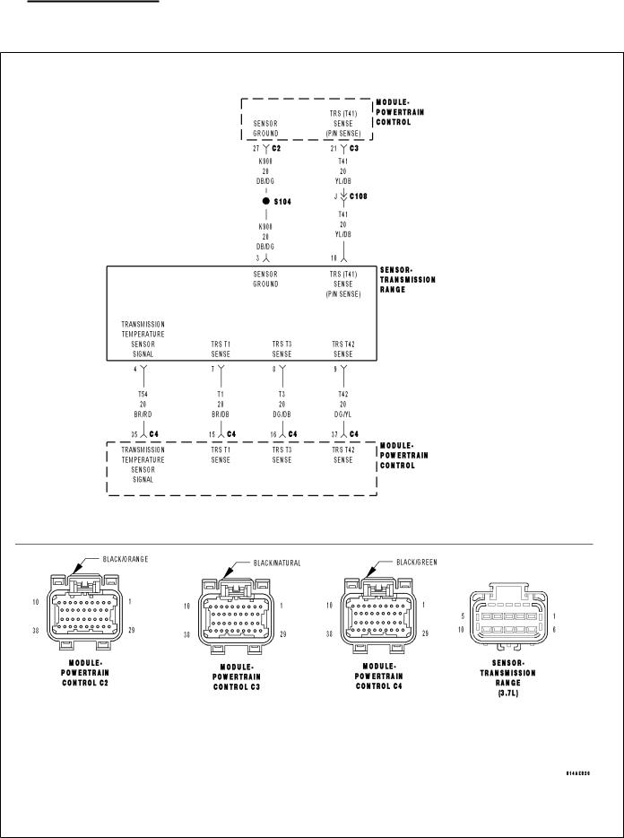
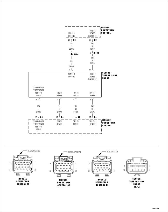
P0706-TRANSMISSION RANGE SENSOR RATIONALITY
For a complete wiring diagram Refer to Section 8W.

DR AUTOMATIC TRANSMISSION 42RLE - ELECTR
• When Monitored:
Continuously with the ignition on.
• Set Condition:
The DTC will set if the controller detects an invalid PRNDL code which lasts for more than 0.042 seconds.
Possible Causes
SHIFTER OUT OF ADJUSTMENT
TRS SENSE CIRCUIT OPEN
TRS SENSE CIRCUIT SHORT TO GROUND
TRS SENSE CIRCUIT SHORT TO VOLTAGE
METAL DEBRIS IN OIL PAN
TRANSMISSION RANGE SENSOR
POWERTRAIN CONTROL MODULE
Always perform the 42RLE Pre-Diagnostic Troubleshooting procedure before proceeding. (Refer to 21 - TRANSMISSION/TRANSAXLE/AUTOMATIC - 42RLE - STANDARD PROCEDURE)
Theory of Operation
The C1 through C4 (T1, T3, T41, and T42) sense circuits communicate the shift lever position to the PCM. Each circuit is terminated at the transmission with a switch. Each switch can be either open or closed, depending on the shift lever position. The PCM can decode this information and determine the shift lever position. Each shift lever position has a certain combination of switches, which will be open and closed, this is called a PRNDL code. There are 4 switches, therefore: there are many possible combinations of open and closed switches (codes). However, there are only 9 valid codes (8 for AutoStick), one for each gear position and three recognized between gear codes. The remainder of the codes should never occur, these are called invalid codes. The following chart shows the normal switch states for each shift lever position.
TRS SWITCH STATES
SLP |
T42 |
T41 |
T3 |
T1 |
|
|
|
|
|
P |
CLOSED |
CLOSED |
CLOSED |
OPEN |
|
|
|
|
|
R |
CLOSED |
OPEN |
OPEN |
OPEN |
|
|
|
|
|
N |
CLOSED |
CLOSED |
OPEN |
CLOSED |
|
|
|
|
|
OD |
OPEN |
OPEN |
OPEN |
CLOSED |
|
|
|
|
|
3 |
OPEN |
OPEN |
CLOSED |
OPEN |
|
|
|
|
|
L |
CLOSED |
OPEN |
CLOSED |
CLOSED |
|
|
|
|
|
Diagnostic Test
1. CHECK TO SEE IF P0706 DTC IS CURRENT
With the scan tool, perform the Shift Lever Position Test.
Select the test outcome from the following:
Test passes:
Go To 6
Test fails with Error Code:
Go To 2
Test fails without Error Code:
Perform the Gearshift Adjustment Procedure per the Service Information.
Perform the PRNDL Fault Clearing Procedure – Go To 7
21 - 222 AUTOMATIC TRANSMISSION 42RLE - ELECTRICADR
2. CHECK THE TRANSMISSION SOLENOID/TRS ASSEMBLY
Turn the ignition off to the lock position.
Remove the Ignition Switch Feed fuse from the TIPM.
CAUTION: Removal of the Ignition Switch Feed fuse from the TIPM will prevent the vehicle from being started in gear.
WARNING: The Ignition Switch Feed fuse must be removed from the TIPM. Failure to do so can result in personal injury or death.
Install the Transmission Simulator, Miller tool #8333 and the Electronic Transmission Adapter kit. Ignition on, engine not running.
With the scan tool, perform the Shift Lever Position Test.
When the scan tool instructs you to put the Gear Selector in a particular position, you must do so using the selector switch on the Transmission Simulator.
The LED for the gear position in question must be illuminated on the Transmission Simulator prior to pressing 9ENTER9 on the scan tool.
NOTE: When the scan tool requests the O/D off button be depressed, you must use the O/D OFF button in the vehicle or you will fail the Shift Lever Position Test with an error code 11 or OD-TOW/HALL STUCK OPEN.
NOTE: If the Shift Lever Position test fails, make sure to note the identification of the TRS Sense circuit for future reference.
Did the Shift Lever Position test pass?
Yes >> Remove the Oil Pan and Main Valve Body Assembly per the Service Information. Check for metal debris on top of the TRS Assembly. If debris is present, determine the cause of the debris and repair the transmission as necessary. If no problems are found, replace the Transmission TRS Assembly per the Service Information.
Perform the PRNDL Fault Clearing Procedure – Go To 7
No >> Go To 3
3. TRS SENSE CIRCUIT OPEN
Turn the ignition off to the lock position.
Disconnect the Transmission Simulator, Miller tool #8333.
Disconnect the PCM harness connectors and install Miller tool #8815.
CAUTION: Do not probe the PCM harness connectors. Probing the PCM harness connectors will damage the PCM terminals resulting in poor terminal to pin connection. Install Miller tool #8815 to perform diagnosis.
Measure the resistance of the identified (T1, T3, T41, or T42) TRS Sense circuit, from the Transmission Solenoid/ TRS Assembly harness connector to the appropriate terminal of Miller tool #8815.
Is the resistance above 5.0 ohms?
Yes >> Repair the identified (T1, T3, T41, or T42) TRS Sense circuit for an open.
Perform the PRNDL Fault Clearing Procedure – Go To 7
No >> Go To 4

DR AUTOMATIC TRANSMISSION 42RLE - ELECTR
4. TRS SENSE CIRCUIT SHORT TO GROUND
Measure the resistance between ground and the identified (T1, T3, T41, or T42) TRS Sense circuit.
Is the resistance below 5.0 ohms?
Yes >> Repair the identified (T1, T3, T41, or T42) TRS Sense circuit for a short to ground. Perform the PRNDL Fault Clearing Procedure – Go To 7
No >> Go To 5
5. TRS SENSE CIRCUIT SHORT TO OTHER CIRCUITS
Measure the resistance between the identified (T1, T3, T41, or T42) TRS Sense circuit and all other circuits in the Transmission Solenoid/TRS Assembly harness connector.
Is the resistance below 100k ohms between the identified (T1, T3, T41, or T42) TRS Sense circuit and any other circuit(s) in the Transmission Solenoid/TRS Assembly harness connector?
Yes >> Repair the identified (T1, T3, T41, or T42) TRS Sense circuit for a short to other circuit(s). Perform the PRNDL Fault Clearing Procedure – Go To 7
No >> Using the schematics as a guide, check the Powertrain Control Module (PCM) terminals for corrosion, damage, or terminal push out. Pay particular attention to all power and ground circuits. If no problems are found, replace the PCM per the Service Information. With the scan tool, perform QUICK LEARN. Perform the PRNDL Fault Clearing Procedure – Go To 7
6. INTERMITTENT WIRING AND CONNECTORS
The conditions necessary to set the DTC are not present at this time.
Using the schematics as a guide, inspect the wiring and connectors specific to this circuit. Wiggle the wiring and connectors while checking for shorted and open circuits.
With the scan tool, check the DTC EVENT DATA to help identify the conditions in which the DTC was set.
Were there any problems found?
Yes >> Repair as necessary.
Perform the PRNDL Fault Clearing Procedure – Go To 7
No >> Test Complete.
7. PRNDL FAULT CLEARING PROCEDURE

21 - 224 AUTOMATIC TRANSMISSION 42RLE - ELECTRICADR
P0711-TRANSMISSION TEMPERATURE SENSOR PERFORMANCE
For a complete wiring diagram Refer to Section 8W.

DR AUTOMATIC TRANSMISSION 42RLE - ELECTR
• When Monitored:
Continuously with the ignition on and engine running.
• Set Condition:
DTC will set when the transmission temperature does not reach a normal operating temperature within a given time frame. Time is variable due to ambient temperature. Approximate DTC set time is 10 to 35 minutes. The following are starting temperature to warm up times to set this DTC: starting temperature -40° C (-40° F) warm up time 35 minutes, starting temperature -28° C ( -20° F) 25 minutes, starting temperature -6.6° C (20° F) 20 minutes, starting temperature 15.5 ° C (60° F) 10 minutes. When the fault is set, calculated temperature is substituted for measured temperature, however the DTC is stored only after three consecutive occurrences.
Possible Causes
RELATED TRANSMISSION TEMPERATURE DTC’S PRESENT
TRANSMISSION TEMPERATURE SENSOR
POWERTRAIN CONTROL MODULE
Always perform the Pre-Diagnostic Troubleshooting procedure before proceeding. (Refer to 21 - TRANSMISSION/TRANSAXLE/AUTOMATIC - 42RLE - STANDARD PROCEDURE)
Theory of Operation
The temperature sensor is used to sense the temperature of the transmission fluid. Transmission fluid temperature can affect shift quality, torque converter operation and when or if some diagnostics are run. A failed temperature sensor could affect the OBD diagnostics. If a problem occurs in the transmission temperature sensor circuit, transmission temperature will be based on a calculated value.
Diagnostic Test
1. DETERMINE IF RELATED TRANSMISSION TEMPERATURE DTCS ARE PRESENT
With the scan tool, check Transmission DTCs.
Are there any other Transmission Temperature Sensor related DTCs present?
Yes
No
2.
With the scan tool, view DTCs.
Is the status Active for this DTC or is the STARTS SINCE SET counter 2 or less?
Yes >> Go To 3
No >> Go To 4
3. PCM AND WIRING
Turn the ignition off to the lock position.
Remove the Ignition Switch Feed fuse from the TIPM.
CAUTION: Removal of the Ignition Switch Feed fuse from the TIPM will prevent the vehicle from being started in gear.
WARNING: The Ignition Switch Feed fuse must be removed from the TIPM. Failure to do so can result in personal injury or death.
Install the Transmission Simulator, Miller tool #8333 and the Electronic Transmission Adapter kit. Ignition on, engine not running.
With the Transmission Simulator, turn the Input/Output switch to OFF.
With the scan tool, monitor the TRANS TEMP VOLTS while turning the Thermistor Voltage switch to all three positions on the Transmission Simulator.

21 - 226 AUTOMATIC TRANSMISSION 42RLE - ELECTRICADR
Compare the scan tool readings with the numbers listed on the Transmission Simulator.
Do the readings on the Transmission Simulator match the scan tool readings ± 0.2 volts?
Yes >> Replace Transmission Solenoid/TRS Assembly per the Service Information.
Perform 42RLE TRANSMISSION VERIFICATION TEST - VER 1. (Refer to 21 - TRANSMISSION/ TRANSAXLE/AUTOMATIC - 42RLE - STANDARD PROCEDURE)
No >> Using the schematics as a guide, check the Powertrain Control Module (PCM) terminals for corrosion, damage, or terminal push out. Pay particular attention to all power and ground circuits. Check for any Service Bulletins and S.T.A.R. ON-LINE for any possible causes that may apply. If no problems are found, replace the PCM per the Service Information. With the scan tool, perform QUICK LEARN.
Perform 42RLE TRANSMISSION VERIFICATION TEST - VER 1. (Refer to 21 - TRANSMISSION/ TRANSAXLE/AUTOMATIC - 42RLE - STANDARD PROCEDURE)
4. INTERMITTENT WIRING AND CONNECTORS
The conditions necessary to set this DTC are not present at this time.
Using the schematics as a guide, inspect the wiring and connectors specific to this circuit. Wiggle the wires while checking for shorted and open circuits.
With the scan tool, check the DTC EVENT DATA to help identify the conditions in which the DTC was set.
Were there any problems found?
Yes >> Repair as necessary.
Perform 42RLE TRANSMISSION VERIFICATION TEST - VER 1. (Refer to 21 - TRANSMISSION/ TRANSAXLE/AUTOMATIC - 42RLE - STANDARD PROCEDURE)
No >> Test Complete.
DR AUTOMATIC TRANSMISSION 42RLE - ELECTR
P0712-TRANSMISSION TEMPERATURE SENSOR LOW
For a complete wiring diagram Refer to Section 8W.

21 - 228 AUTOMATIC TRANSMISSION 42RLE - ELECTRICADR
• When Monitored:
Continuously with the ignition on and engine running.
• Set Condition:
The DTC will set when the monitored Temperature Sensor voltage drops below 0.078 volts for the period of 1.45 seconds. When the fault is set, calculated temperature is substituted for measured temperature, however the fault code is stored only after three consecutive occurrences of the fault.
Possible Causes
RELATED DTCS PRESENT
(T54) TRANSMISSION TEMPERATURE SENSOR SIGNAL CIRCUIT SHORT TO GROUND
TRANSMISSION TEMPERATURE SENSOR
POWERTRAIN CONTROL MODULE
Always perform the Pre-Diagnostic Troubleshooting procedure before proceeding. (Refer to 21 - TRANSMISSION/TRANSAXLE/AUTOMATIC - 42RLE - STANDARD PROCEDURE)
Theory of Operation
The temperature sensor is used to sense the temperature of the transmission fluid. Transmission fluid temperature can affect shift quality, torque converter operation and when or if some diagnostics are run. A failed temperature sensor could affect the OBD diagnostics. If a problem occurs in the transmission temperature sensor circuit, transmission temperature will be based on a calculated value.
Diagnostic Test
1. DETERMINE IF RELATED DTCS ARE PRESENT
With the scan tool, check Transmission DTCs.
Are there any Speed Sensor DTCs present?
Yes >> Refer to the Transmission category and perform the appropriate diagnostic procedure.
No >> Go To 2
2. CHECK TO SEE IF DTC IS ACTIVE
With the scan tool, view DTCs.
Is the status Active for this DTC or is the STARTS SINCE SET counter 2 or less?
Yes >> Go To 3
No >> Go To 5
3. CHECK THE PCM AND WIRING WITH THE TRANSMISSION SIMULATOR
Turn the ignition off to the lock position.
Remove the Ignition Switch Feed fuse from the TIPM.
CAUTION: Removal of the Ignition Switch Feed fuse from the TIPM will prevent the vehicle from being started in gear.
WARNING: The Ignition Switch Feed fuse must be removed from the TIPM. Failure to do so can result in personal injury or death.
Install the Transmission Simulator, Miller tool #8333 and the Electronic Transmission Adapter kit. Ignition on, engine not running.
With the Transmission Simulator, turn the Input/Output switch to OFF.
With the scan tool, monitor the TRANS TEMP VOLTS while turning the Thermistor Voltage switch to all three positions on the Transmission Simulator.

CompareDR the scan tool readings with the numbers listed on the Transmission Simulator.
Do the readings on the Transmission Simulator match the scan tool readings ± 0.2 volts?
Yes >> Replace Transmission Solenoid Assembly per the Service Information.
Perform 42RLE TRANSMISSION VERIFICATION TEST - VER 1. (Refer to 21 - TRANSMISSION/ TRANSAXLE/AUTOMATIC - 42RLE - STANDARD PROCEDURE)
No >> Go To 4
4. CHECK THE (T54) TRANSMISSION TEMPERATURE SENSOR SIGNAL CIRCUIT FOR A SHORT TO
GROUND
Turn the ignition off to the lock position.
Disconnect the PCM C4 harness connector.
Disconnect the TRS harness connector.
CAUTION: Do not probe the PCM harness connectors. Probing the PCM harness connectors will damage the PCM terminals resulting in poor terminal to pin connection. Install Miller tool #8815 to perform diagnosis.
Measure the resistance between ground and the (T54) Transmission Temperature Sensor Signal circuit.
Is the resistance below 5.0 ohms?
Yes >> Repair the (T54) Transmission Temperature Sensor Signal circuit for a short to ground.
Perform 42RLE TRANSMISSION VERIFICATION TEST - VER 1. (Refer to 21 - TRANSMISSION/TRANSAXLE/AUTOMATIC - 42RLE - STANDARD PROCEDURE)
No >> Using the schematics as a guide, check the Powertrain Control Module (PCM) terminals for corrosion, damage, or terminal push out. Pay particular attention to all power and ground circuits. Check for Service Information Tune-ups or Service Bulletins for any possible causes that may apply. If no problems are found, replace the PCM per the Service Information. With the scan tool, perform QUICK LEARN.
Perform 42RLE TRANSMISSION VERIFICATION TEST - VER 1. (Refer to 21 - TRANSMISSION/TRANSAXLE/AUTOMATIC - 42RLE - STANDARD PROCEDURE)
5. INTERMITTENT WIRING AND CONNECTORS
The conditions necessary to set this DTC are not present at this time.
Using the schematics as a guide, inspect the wiring and connectors specific to this circuit. Wiggle the wires while checking for shorted and open circuits.
With the scan tool, check the DTC EVENT DATA to help identify the conditions in which the DTC was set. Check for any Service Information Tune-ups or Service Bulletins for any possible causes that may apply.
Were there any problems found?
Yes >> Repair as necessary.
Perform 42RLE TRANSMISSION VERIFICATION TEST - VER 1. (Refer to 21 - TRANSMISSION/ TRANSAXLE/AUTOMATIC - 42RLE - STANDARD PROCEDURE)
No >> Test Complete.
21 - 230 AUTOMATIC TRANSMISSION 42RLE - ELECTRICADR
P0713-TRANSMISSION TEMPERATURE SENSOR HIGH
For a complete wiring diagram Refer to Section 8W.

DR AUTOMATIC TRANSMISSION 42RLE - ELECTR
• When Monitored:
Continuously with the ignition on and engine running.
• Set Condition:
The DTC will set when the monitored Temperature Sensor voltage rises above 4.94 volts for the period of 1.45 seconds. When the fault is set, calculated temperature is substituted for measured temperature, however the fault code is stored only after three consecutive occurrences of the fault.
Possible Causes
(K900) SENSOR GROUND OPEN
(T54) TRANSMISSION TEMPERATURE SENSOR SIGNAL CIRCUIT OPEN
(T54) TRANSMISSION TEMPERATURE SENSOR SIGNAL CIRCUIT SHORT TO VOLTAGE
TRANSMISSION TEMPERATURE SENSOR
POWERTRAIN CONTROL MODULE
Always perform the Pre-Diagnostic Troubleshooting procedure before proceeding. (Refer to 21 - TRANSMISSION/TRANSAXLE/AUTOMATIC - 42RLE - STANDARD PROCEDURE)
Theory of Operation
The temperature sensor is used to sense the temperature of the transmission fluid. Transmission fluid temperature can affect shift quality, torque converter operation and when or if some diagnostics are run. A failed temperature sensor could affect the OBD diagnostics. If a problem occurs in the transmission temperature sensor circuit, transmission temperature will be based on a calculated value.
1. CHECK TO SEE IF DTC IS CURRENT
With the scan tool, view DTCs.
Is the status Active for this DTC or is STARTS SINCE SET counter 2 or less?
Yes >> Go To 2
No >> Go To 6
2. CHECK THE PCM AND WIRING WITH THE TRANSMISSION SIMULATOR
Turn the ignition off to the lock position.
Remove the Ignition Switch Feed fuse from the TIPM.
CAUTION: Removal of the Ignition Switch Feed fuse from the TIPM will prevent the vehicle from being started in gear.
WARNING: The Ignition Switch Feed fuse must be removed from the TIPM. Failure to do so can result in personal injury or death.
Install the Transmission Simulator, Miller tool #8333 and the Electronic Transmission Adapter kit 8333-1A. Ignition on, engine not running.
With the Transmission Simulator, turn the Input/Output switch to OFF.
With the scan tool, monitor the TRANS TEMP VOLTS while turning the Thermistor Voltage switch to all three positions on the Transmission Simulator.
Compare the scan tool readings with the numbers listed on the Transmission Simulator.
Do the readings on the Transmission Simulator match the scan tool readings ± 0.2 volts?
Yes >> Replace Transmission Solenoid/Pressure Switch Assembly per the Service Information.
Perform 42RLE TRANSMISSION VERIFICATION TEST - VER 1. (Refer to 21 - TRANSMISSION/ TRANSAXLE/AUTOMATIC - 42RLE - STANDARD PROCEDURE)
No >> Go To 3
 Loading...