


DES-3200-10

User Manual
Product Model:
Layer 2 Managed Ethernet Switch
Release 1.1
DES-3200-10/18/28/28F
®

_________________________________________________________________________________
Information in this document is subject to change without notice.
© 2009 D-Link Corporation. All rights reserved.
Reproduction in any manner whatsoever without the written permission of D-Link Corporation is strictly forbidden.
Trademarks used in this text: D-Link and the D-LINK logo are trademarks of D-Link Corporation; Microsoft and Windows are registered trademarks
of Microsoft Corporation.
Other trademarks and trade names may be used in this document to refer to either the entities claiming the marks and names or their products.
D-Link Corporation disclaims any proprietary interest in trademarks and trade names other than its own.
August 2009 P/N
651S3200.015G
.

®
xStack
DES-3200-10/18/28/28F Layer 2 Ethernet Managed Switch User Manual
Table of Contents
Intended Readers ....................................................................................................................................................... viii
Typographical Conventions...................................................................................................................................................... viii
Notes, Notices, and Cautions ..................................................................................................................................... viii
Web-based Switch Configuration ................................................................................................. 9
Introduction ................................................................................................................................................................... 9
Login to Web Manager ............................................................................................................................................................... 9
Web-based User Interface ....................................................................................................................................................... 10
Web Pages .............................................................................................................................................................................. 11
Configuration ............................................................................................................................... 12
Device Information ...................................................................................................................................................... 13
System Information ..................................................................................................................................................... 13
Serial Port Settings ..................................................................................................................................................... 14
IP Address Settings .................................................................................................................................................... 14
IPv6 Address Settings ................................................................................................................................................ 16
IPv6 Route Settings .................................................................................................................................................... 17
IPv6 Neighbor Settings ............................................................................................................................................... 17
Port Configuration ....................................................................................................................................................... 18
Port Settings ............................................................................................................................................................................ 18
Port Description Settings ......................................................................................................................................................... 20
Port Error Disabled .................................................................................................................................................................. 20
Static ARP Settings .................................................................................................................................................... 21
User Accounts ............................................................................................................................................................ 22
System Log Configuration .......................................................................................................................................... 23
System Log Settings ................................................................................................................................................................ 23
System Log Server .................................................................................................................................................................. 23
DHCP Relay ............................................................................................................................................................... 25
DHCP Relay Global Settings ................................................................................................................................................... 25
DHCP Relay Interface Settings ................................................................................................................................................ 28
DHCP Local Relay Settings ..................................................................................................................................................... 28
DHCP Auto Configuration Settings ............................................................................................................................. 29
MAC Address Aging Time .......................................................................................................................................... 29
Web Settings .............................................................................................................................................................. 29
Telnet Settings ............................................................................................................................................................ 30
Password Encryption .................................................................................................................................................. 30
CLI Paging Settings .................................................................................................................................................... 30
Firmware Information .................................................................................................................................................. 31
SNTP Settings ............................................................................................................................................................ 32
Time Settings ........................................................................................................................................................................... 32
Time Zone Settings .................................................................................................................................................................. 33
ii

xStack
®
DES-3200-10/18/28/28F Layer 2 Ethernet Managed Switch User Manual
SMTP Settings ............................................................................................................................................................ 35
SMTP Service Settings ............................................................................................................................................................ 35
SMTP Service .......................................................................................................................................................................... 36
MAC Notification Settings ........................................................................................................................................... 36
MAC Notification Global Settings ............................................................................................................................................. 36
MAC Notification Port Settings ................................................................................................................................................. 36
SNMP Settings ........................................................................................................................................................... 37
SNMP View Table .................................................................................................................................................................... 38
SNMP Group Table .................................................................................................................................................................. 39
SNMP User Table .................................................................................................................................................................... 40
SNMP Community Table.......................................................................................................................................................... 41
SNMP Host Table .................................................................................................................................................................... 42
SNMP Engine ID ...................................................................................................................................................................... 42
SNMP Trap Configuration ........................................................................................................................................................ 43
RMON ...................................................................................................................................................................................... 43
Time Range Settings .................................................................................................................................................. 44
Single IP Management ............................................................................................................................................... 44
Single IP Settings ..................................................................................................................................................................... 46
Topology .................................................................................................................................................................................. 47
Tool Tips .................................................................................................................................................................................. 49
Right-Click ................................................................................................................................................................................ 50
Menu Bar ................................................................................................................................................................................. 52
Firmware Upgrade ................................................................................................................................................................... 53
Configuration File Backup/Restore .......................................................................................................................................... 53
Upload Log File ........................................................................................................................................................................ 54
Gratuitous ARP ........................................................................................................................................................... 54
Gratuitous ARP Global Settings ............................................................................................................................................... 54
Gratuitous ARP Settings .......................................................................................................................................................... 55
ARP Spoofing Prevention Settings ............................................................................................................................. 56
L2 Features ................................................................................................................................... 57
Jumbo Frame .............................................................................................................................................................. 57
VLANs ......................................................................................................................................................................... 58
Understanding IEEE 802.1p Priority ........................................................................................................................................ 58
VLAN Description ..................................................................................................................................................................... 58
IEEE 802.1Q VLANs ................................................................................................................................................................ 59
Q-in-Q VLANs .......................................................................................................................................................................... 62
802.1Q Static VLAN ................................................................................................................................................................. 64
Q-in-Q ......................................................................................................................................................................... 67
Q-in-Q Settings ........................................................................................................................................................................ 68
VLAN Translation Settings ....................................................................................................................................................... 69
802.1v Protocol VLAN ................................................................................................................................................ 69
802.1v Protocol Group Settings ............................................................................................................................................... 69
802.1v Protocol VLAN Settings ................................................................................................................................................ 70
iii

xStack
®
DES-3200-10/18/28/28F Layer 2 Ethernet Managed Switch User Manual
VLAN Trunk Settings .................................................................................................................................................. 71
GVRP Settings ............................................................................................................................................................ 72
Asymmetric VLAN Settings ......................................................................................................................................... 73
MAC-based VLAN Settings ........................................................................................................................................ 73
PVID Auto Assign Settings ......................................................................................................................................... 74
Port Trunking .............................................................................................................................................................. 74
LACP Port Settings ..................................................................................................................................................... 76
Traffic Segmentation ................................................................................................................................................... 77
BPDU Tunneling Settings ........................................................................................................................................... 78
IGMP Snooping .......................................................................................................................................................... 78
IGMP Snooping Settings .......................................................................................................................................................... 78
IGMP Access Control Settings ................................................................................................................................................. 80
IGMP Snooping Multicast VLAN Settings ................................................................................................................................ 81
IP Multicast Profile Settings ..................................................................................................................................................... 82
Limited Multicast Range Settings ............................................................................................................................................. 84
Max Multicast Group Settings .................................................................................................................................................. 84
MLD Snooping Settings .............................................................................................................................................. 85
Port Mirror ................................................................................................................................................................... 88
Loopback Detection Settings ...................................................................................................................................... 89
Spanning Tree ............................................................................................................................................................ 90
STP Bridge Global Settings ..................................................................................................................................................... 92
STP Port Settings .................................................................................................................................................................... 93
MST Configuration Identification .............................................................................................................................................. 95
STP Instance Settings ............................................................................................................................................................. 96
MSTP Port Information ............................................................................................................................................................ 97
Forwarding & Filtering ................................................................................................................................................. 97
Unicast Forwarding Settings .................................................................................................................................................... 97
Multicast Forwarding Settings .................................................................................................................................................. 98
Multicast Filtering Mode ........................................................................................................................................................... 99
LLDP ........................................................................................................................................................................... 99
LLDP Global Settings ............................................................................................................................................................. 100
LLDP Port Settings ................................................................................................................................................................ 101
LLDP Basic TLVs Settings ..................................................................................................................................................... 102
LLDP Dot1 TLVs Settings ...................................................................................................................................................... 103
LLDP Dot3 TLVs Settings ...................................................................................................................................................... 104
QoS ............................................................................................................................................. 105
Advantages of QoS ................................................................................................................................................................ 105
Understanding QoS ............................................................................................................................................................... 106
Bandwidth Control .................................................................................................................................................... 107
Traffic Control ........................................................................................................................................................... 107
802.1p Default Priority .............................................................................................................................................. 110
802.1p User Priority .................................................................................................................................................. 110
QoS Scheduling Settings .......................................................................................................................................... 111
iv

xStack
®
DES-3200-10/18/28/28F Layer 2 Ethernet Managed Switch User Manual
Priority Mapping ........................................................................................................................................................ 112
TOS Mapping ............................................................................................................................................................ 113
DSCP Mapping ......................................................................................................................................................... 114
Security ....................................................................................................................................... 115
Safeguard Engine ..................................................................................................................................................... 115
Trusted Host ............................................................................................................................................................. 117
IP-MAC-Port Binding ................................................................................................................................................ 117
IMP Binding Global Settings .................................................................................................................................................. 117
IMP Binding Port Settings ...................................................................................................................................................... 118
IMP Binding Entry Settings .................................................................................................................................................... 119
DHCP Snooping Entries ........................................................................................................................................................ 120
MAC Block List ....................................................................................................................................................................... 120
Port Security ............................................................................................................................................................. 120
Port Security Port Settings ..................................................................................................................................................... 120
Port Security FDB Entries ...................................................................................................................................................... 122
802.1X ....................................................................................................................................................................... 122
Understanding 802.1X Port-based and MAC-based Network Access Control ....................................................................... 125
Port-Based Network Access Control ...................................................................................................................................... 125
MAC-Based Network Access Control .................................................................................................................................... 126
802.1X Settings ...................................................................................................................................................................... 127
802.1X User ........................................................................................................................................................................... 128
Authentication RADIUS Server .............................................................................................................................................. 129
Guest VLAN Configuration ..................................................................................................................................................... 130
Guest VLAN ........................................................................................................................................................................... 131
Initialize Port(s) ...................................................................................................................................................................... 131
Reauthenticate Port(s) ........................................................................................................................................................... 132
SSL Settings ............................................................................................................................................................. 133
Download Certificate .............................................................................................................................................................. 134
Ciphersuite ............................................................................................................................................................................. 134
SSH ........................................................................................................................................................................... 135
SSH Settings .......................................................................................................................................................................... 136
SSH Authmode and Algorithm Settings ................................................................................................................................. 136
SSH User Authentication Lists ............................................................................................................................................... 138
Access Authentication Control .................................................................................................................................. 139
Authentication Policy Settings ................................................................................................................................................ 140
Application Authentication Settings ........................................................................................................................................ 140
Authentication Server Group .................................................................................................................................................. 141
Authentication Server ............................................................................................................................................................. 142
Login Method Lists ................................................................................................................................................................. 143
Enable Method Lists .............................................................................................................................................................. 144
Local Enable Password Settings ............................................................................................................................................ 145
MAC-based Access Control ...................................................................................................................................... 146
MAC-based Access Control Settings ..................................................................................................................................... 146
v

®
xStack
MAC-based Access Control Local Settings ........................................................................................................................... 148
DES-3200-10/18/28/28F Layer 2 Ethernet Managed Switch User Manual
DoS Prevention Settings ........................................................................................................................................... 149
ACL ............................................................................................................................................. 150
ACL Configuration Wizard ........................................................................................................................................ 150
Access Profile List .................................................................................................................................................... 151
CPU Interface Filtering ............................................................................................................................................. 168
CPU Access Profile List ............................................................................................................................................ 168
ACL Finder ................................................................................................................................................................ 182
ACL Flow Meter ........................................................................................................................................................ 182
Monitoring .................................................................................................................................. 184
Cable Diagnostic ....................................................................................................................................................... 184
CPU Utilization .......................................................................................................................................................... 184
Port Utilization ........................................................................................................................................................... 185
Packet Size ............................................................................................................................................................... 186
Memory Utilization .................................................................................................................................................... 188
Packets ..................................................................................................................................................................... 188
Received (Rx) ........................................................................................................................................................................ 188
UMB_cast (Rx) ....................................................................................................................................................................... 190
Transmitted (Tx) ..................................................................................................................................................................... 191
Errors ........................................................................................................................................................................ 193
Received (RX) ........................................................................................................................................................................ 193
Transmitted (TX) .................................................................................................................................................................... 195
Port Access Control .................................................................................................................................................. 196
RADIUS Authentication .......................................................................................................................................................... 197
RADIUS Account Client ......................................................................................................................................................... 198
Authenticator State ................................................................................................................................................................ 200
Authenticator Statistics .......................................................................................................................................................... 201
Authenticator Session Statistics ............................................................................................................................................. 202
Authenticator Diagnostics ...................................................................................................................................................... 204
Browse ARP Table ................................................................................................................................................... 206
Browse VLAN ........................................................................................................................................................... 206
IGMP Snooping ........................................................................................................................................................ 206
Browse IGMP Router Port...................................................................................................................................................... 206
IGMP Snooping Group ........................................................................................................................................................... 207
IGMP Snooping Host ............................................................................................................................................................. 208
MLD Snooping .......................................................................................................................................................... 208
Browse MLD Router Port ....................................................................................................................................................... 208
MLD Snooping Group ............................................................................................................................................................ 209
LLDP ......................................................................................................................................................................... 209
LLDP Statistics System .......................................................................................................................................................... 209
LLDP Local Port Information .................................................................................................................................................. 210
LLDP Remote Port Information .............................................................................................................................................. 210
MBA Authentication State ......................................................................................................................................... 211
vi

xStack
®
DES-3200-10/18/28/28F Layer 2 Ethernet Managed Switch User Manual
Browse Session Table .............................................................................................................................................. 211
MAC Address Table .................................................................................................................................................. 211
System Log ............................................................................................................................................................... 212
Save and Tools ........................................................................................................................... 213
Save Configuration ................................................................................................................................................... 213
Save Log ................................................................................................................................................................... 214
Save All ..................................................................................................................................................................... 214
Configuration File Upload & Download ..................................................................................................................... 214
Upload Log File ......................................................................................................................................................... 215
Reset ......................................................................................................................................................................... 215
Ping Test ................................................................................................................................................................... 216
Download Firmware .................................................................................................................................................. 217
Reboot System ......................................................................................................................................................... 217
Mitigating ARP Spoofing Attacks Using Packet Content ACL ............................................... 218
System Log Entries ................................................................................................................... 226
Glossary...................................................................................................................................... 237
vii

®
xStack
DES-3200-10/18/28/28F Layer 2 Ethernet Managed Switch User Manual
Intended Readers
The DES-3200-10/18/28/28F User Manual contains information for setup and management of the Switch. This
manual is intended for network managers familiar with network management concepts and terminology.
Typographical Conventions
Convention Description
[ ] In a command line, square brackets indicate an optional entry. For example: [copy
filename] means that optionally you can type copy followed by the name of the file. Do not
type the brackets.
Bold font
Boldface Typewriter
Font
Initial capital letter Indicates a window name. Names of keys on the keyboard have initial capitals. For
Italics Indicates a window name or a field. Also can indicate a variables or parameter that is
Menu Name > Menu
Option
Indicates a button, a toolbar icon, menu, or menu item. For example: Open the File menu
and choose Cancel. Used for emphasis. May also indicate system messages or prompts
appearing on your screen. For example: You have mail. Bold font is also used to
represent filenames, program names and commands. For example: use the copy
command.
Indicates commands and responses to prompts that must be typed exactly as printed in
the manual.
example: Click Enter.
replaced with an appropriate word or string. For example: type filename means that you
should type the actual filename instead of the word shown in italic.
Menu Name > Menu Option Indicates the menu structure. Device > Port > Port
Properties means the Port Properties menu option under the Port menu option that is
located under the Device menu.
Notes, Notices, and Cautions
A NOTE indicates important information that helps you make better use of your device.
A NOTICE indicates either potential damage to hardware or loss of data and tells you
how to avoid the problem.
A CAUTION indicates a potential for property damage, personal injury, or death.
viii
®
xStack
DES-3200-10/18/28/28F Layer 2 Ethernet Managed Switch User Manual
Section 1
Web-based Switch Configuration
Introduction
Login to Web Manager
Web-based User Interface
Web Pages
Introduction
All software functions of the Switch can be managed, configured and monitored via the embedded web-based (HTML)
interface. The Switch can be managed from remote stations anywhere on the network through a standard browser
such as Firefox, Microsoft Internet Explorer, Mozilla, or Netscape. The browser acts as a universal access tool and
can communicate directly with the Switch using the HTTP protocol.
The Web-based management module and the Console program (and Telnet) are different ways to access the same
internal switching software and configure it. Thus, all settings encountered in Web-based management are the same
as those found in the console program.
Login to Web Manager
To begin managing the Switch, simply run the browser you have installed on your computer and point it to the IP
address you have defined for the device. The URL in the address bar should read something like:
http://123.123.123.123, where the numbers 123 represent the IP address of the Switch.
NOTE: The Factory default IP address for the Switch is 10.90.90.90.
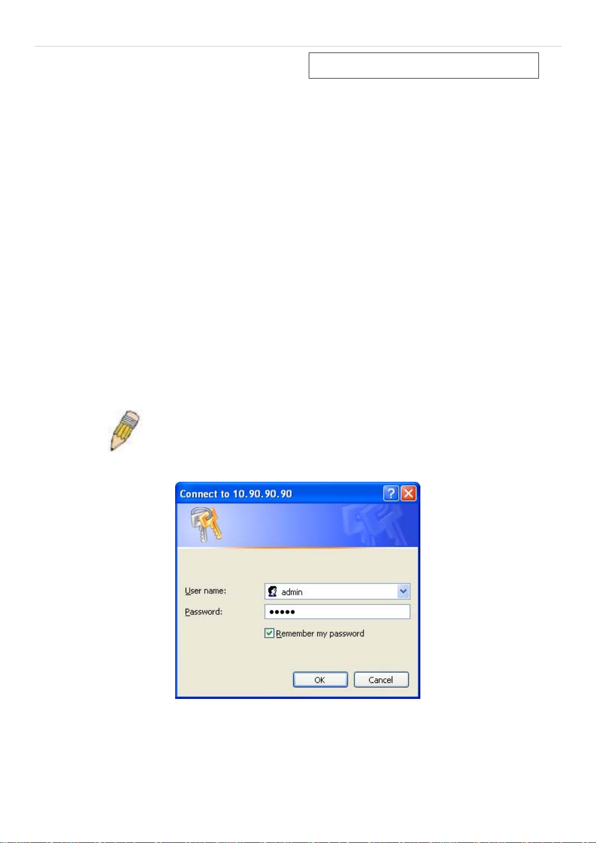
This opens the management module's user authentication window, as seen below.
Figure 1 - 1 Enter Network Password dialog
Enter “admin” in both the User Name and Password fields and click OK. This will open the Web-based user interface.
The Switch management features available in the web-based manager are explained below.
9
®
xStack
DES-3200-10/18/28/28F Layer 2 Ethernet Managed Switch User Manual
Web-based User Interface
The user interface provides access to various Switch configuration and management windows, allows you to view
performance statistics, and permits you to graphically monitor the system status.
Areas of the User Interface
The figure below shows the user interface. The user interface is divided into three distinct areas as described in the
table.
Area 2
Area 1
Area Function
Area 1
Select the folder or window to be displayed. The folder icons can be opened to display the
hyperlinked window buttons and subfolders contained within them. Click the D-Link logo to go to the
D-Link website.
Area
Figure 1 - 2 Main Web-Manager page
Area 2
Area 3
Presents a graphical near real-time image of the front panel of the Switch. This area displays the
Switch's ports and expansion modules, showing port activity, duplex mode, or flow control,
depending on the specified mode.
Various areas of the graphic can be selected for performing management functions, including port
configuration.
Presents switch information based on your selection and the entry of configuration data.
10

xStack
®
DES-3200-10/18/28/28F Layer 2 Ethernet Managed Switch User Manual
NOTICE: Any changes made to the Switch configuration during the current
session must be saved in the Save Configuration window (Save > Save
Configuration) or use the command line interface (CLI) command save
config.
Web Pages
When you connect to the management mode of the Switch with a Web browser, a login window is displayed. Enter a
user name and password to access the Switch's management mode.
Below is a list and description of the main folders available in the Web interface:
Configuration – Contains main windows concerning Device Information, System Information, Serial Port Settings, IP
Address, IPv6 Interface Settings, IPv6 Route Settings, IPv6 Neighbor Settings, Port Configuration, Static ARP
Settings, User Accounts, System Log Configuration, DHCP Relay, DHCP Auto Configuration Settings, MAC Address
Aging Time, Web Settings, Telnet Settings, Password Encryption, CLI Paging Settings, Firmware Information, SNTP
Settings, SMTP Settings, MAC Notification Settings, SNMP Settings, Time Range Settings, Single IP Management,
Gratuitous ARP, and ARP Spoofing Prevention Settings.
L2 Features – Contains main windows concerning Jumbo Frame, 802.1Q Static VLAN, Q-in-Q, 802.1v Protocol VLAN,
VLAN Trunk Settings, GVRP Settings, Asymmetric VLAN Settings, MAC-based VLAN Settings, PVID Auto Assign
Settings, Port Trunking, LACP Port Settings, Traffic Segmentation, BPDU Tunneling Settings, IGMP Snooping, MLD
Snooping Settings, Port Mirror, Loopback Detection Settings, Spanning Tree, Forwarding & Filtering, and LLDP.
QoS – Contains main windows concerning Bandwidth Control, Traffic Control, 802.1P Default Priority, 802.1P User
Priority, QoS Scheduling Settings, Priority Mapping, TOS Mapping, and DSCP Mapping.
Security – Contains main windows concerning Safeguard Engine, Trusted Host, IP-MAC-Port Binding, Port Security,
802.1X, SSL Settings, SSH, Access Authentication Control, MAC-based Access Control, and DoS Prevention Settings.
ACL – Contains main windows concerning ACL Configuration Wizard, Access Profile List, CPU Access Profile List,
ACL Finder, and ACL Flow Meter.
Monitoring – Contains main windows concerning Cable Diagnostic, CPU Utilization, Port Utilization, Packet Size,
Memory Utilization, Packets, Errors, Port Access Control, Browse ARP Table, Browse VLAN, IGMP Snooping, MLD
Snooping, LLDP, MBA Authentication State, Browse Session Table, MAC Address Table, and System Log.
Save & Tools – Contains main windows concerning Save Configuration, Save Log, Save All, Configuration File
Upload & Download, Upload Log File, Reset, Ping Test, Download Firmware, and Reboot System.
NOTE: Be sure to configure the user name and password in the User
Accounts window (Configuration > User Accounts) before connecting
the Switch to the greater network.
11

®
xStack
DES-3200-10/18/28/28F Layer 2 Ethernet Managed Switch User Manual
Configuration
Device Information
System Information
Serial Port Settings
IP Address Settings
IPv6 Interface Settings
IPv6 Route Settings
IPv6 Neighbor Settings
Port Configuration
Static ARP Settings
User Accounts
System Log Configuration
Section 2
DHCP Relay
DHCP Auto Configuration Settings
MAC Address Aging Time
Web Settings
Telnet Settings
Password Encryption
CLI Paging Settings
Firmware Information
SNTP Settings
SMTP Settings
MAC Notification Settings
SNMP Settings
Time Range Settings
Single IP Management
Gratuitous ARP
ARP Spoofing Prevention Settings
12
®
xStack
DES-3200-10/18/28/28F Layer 2 Ethernet Managed Switch User Manual
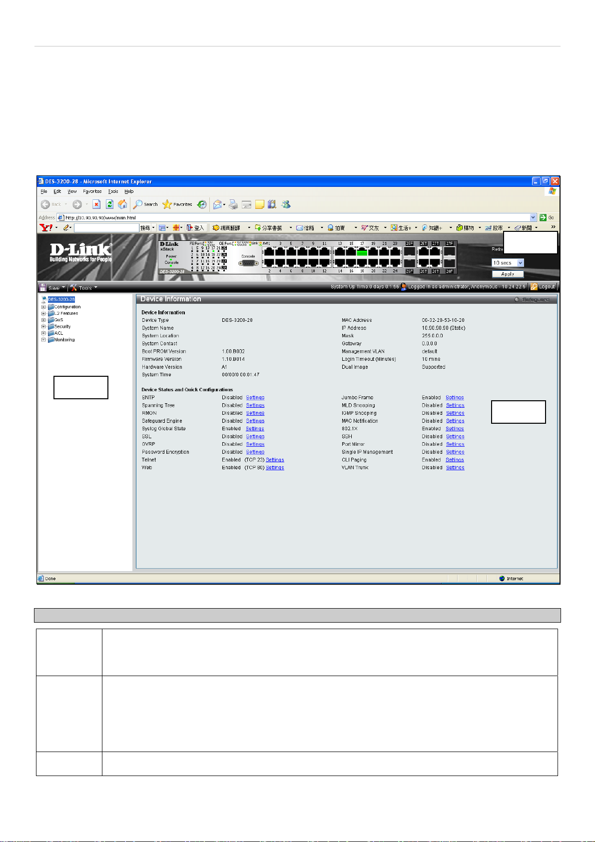
Device Information
This window contains the main settings for all major functions on the Switch and appears automatically when you log
on. To return to the Device Information window, click the DES-3200-10/18/28/28F folder. The Device Information
window shows the Switch’s MAC Address (assigned by the factory and unchangeable), the Boot PROM Version,
Firmware Version, the Hardware Version, and other information about different settings on the Switch. This
information is helpful to keep track of PROM and firmware updates and to obtain the Switch's MAC address for entry
into another network device's address table, if necessary. In addition, this window displays the status of functions on
the Switch to quickly assess their current global status. Some functions are hyper-linked to their configuration window
for easy access from the Device Information window.
Figure 2 - 1. Device Information window
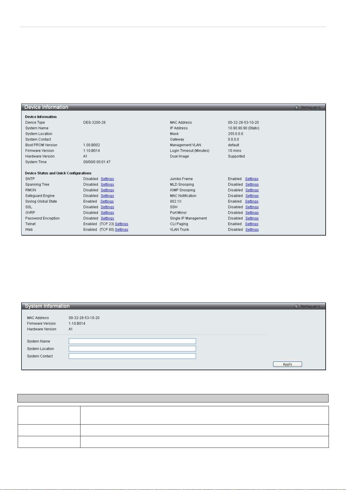
System Information
This window contains the System Information details. The user may enter a System Name, System Location and
System Contact to aid in defining the Switch, to the user's preference. This window displays the MAC Address,
Firmware Version and Hardware Version.
Click Configuration > System Information to display the following window:
Figure 2 - 2. System Information window
The fields that can be configured are described below:
Parameter Description
System Name Enter a system name for the Switch, if so desired. This name will identify it in the Switch
network.
System Location
System Contact
Click Apply to implement changes made.
Enter the location of the Switch, if so desired.
Enter a contact name for the Switch, if so desired.
13
®
xStack
DES-3200-10/18/28/28F Layer 2 Ethernet Managed Switch User Manual
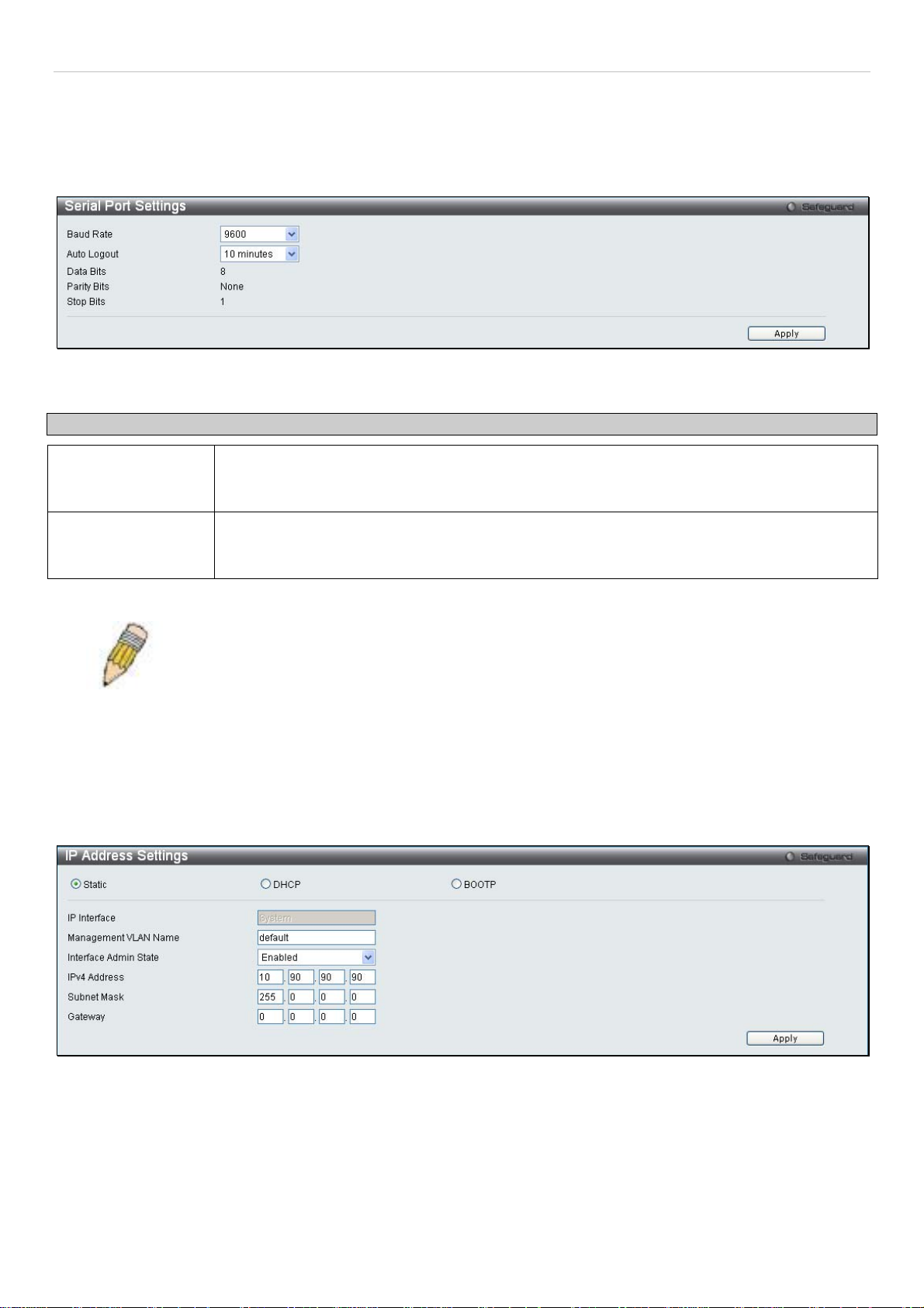
Serial Port Settings
The following window allows the Baud Rate and the Auto Logout to be changed as well as containing information
about the Serial Port Settings.
Click Configuration > Serial Port Settings to display this window:
Figure 2 - 3. Serial Port Settings window
Parameter Description
Baud Rate This field specifies the baud rate for the serial port on the Switch. There are four possible
baud rates to choose from, 9600, 19200, 38400 and 115200. For a connection to the Switch
using the CLI interface, the baud rate must be set to 9600, which is the default setting.
Auto Logout Select the logout time used for the console interface. This automatically logs the user out after
an idle period of time, as defined. Choose from the following options: 2 Minutes, 5 Minutes, 10
Minutes, 15 Minutes or Never. The default setting is 10 minutes.
Click Apply to implement changes made.
NOTE: If a user configures the serial port’s baud rate, the baud rate will take effect and save
immediately.
IP Address Settings
The IP address may initially be set using the console interface prior to connecting to it through the Ethernet. If the
Switch IP address has not yet been changed, read the introduction of the DES-3200-10/18/28/28F CLI Reference
Manual for more information.
Click Configuration > IP Address Settings to display the following window:
Figure 2 - 4. IP Address Settings window
To manually assign the Switch's IP address, subnet mask, and default gateway address:
1. Click Static at the top of the window.
2. Enter the appropriate IPv4 Address and Subnet Mask.
3. To access the Switch from a different subnet from the one it is installed on, enter the IP address of the
Gateway. If the Switch will be managed from the subnet on which it is installed, leave the default address
(0.0.0.0) in this field.
14

®
xStack
DES-3200-10/18/28/28F Layer 2 Ethernet Managed Switch User Manual
4. If no VLANs have been previously configured on the Switch, you can use the default Management VLAN
Name. The default VLAN contains all of the Switch ports as members. If VLANs have been previously
configured on the Switch, the Management VLAN Name of the VLAN that contains the port connected to the
management station will have to be entered to access the Switch.
5. Use the drop-down Interface Admin State menu to select Enabled if it has not already been done.
NOTE: The Switch's factory default IP address is 10.90.90.90 with a
subnet mask of 255.0.0.0 and a default gateway of 0.0.0.0.
To use the BOOTP or DHCP protocols to assign the Switch an IP address, subnet mask, and default gateway address,
select either BOOTP or DHCP.
The IP Address Settings options are:
Parameter Description
Static
DHCP
BOOTP
IP Interface
Management
VLAN Name
Interface Admin
State
Allows the entry of an IPv4 address, Subnet Mask, and a Default Gateway for the Switch. These
fields should be of the form xxx.xxx.xxx.xxx, where each xxx is a number (represented in decimal
form) between 0 and 255. This address should be a unique address on the network assigned for
use by the network administrator.
The Switch will send out a DHCP broadcast request when it is powered up. The DHCP protocol
allows IP addresses, network masks, and default gateways to be assigned by a DHCP server. If
this option is set, the Switch will first look for a DHCP server to provide it with this information
before using the default or previously entered settings.
The Switch will send out a BOOTP broadcast request when it is powered up. The BOOTP
protocol allows IP addresses, network masks, and default gateways to be assigned by a central
BOOTP server. If this option is set, the Switch will first look for a BOOTP server to provide it with
this information before using the default or previously entered settings.
The current IP Interface being assigned an IP address on this window.
This allows the entry of a VLAN Name from which a management station will be allowed to
manage the Switch using TCP/IP (in-band via web manager or Telnet). Management stations that
are on VLANs other than the one entered here will not be able to manage the Switch in-band
unless their IP addresses are entered in the Security IP Management window. If VLANs have
not yet been configured for the Switch, the default VLAN contains all of the Switch's ports. There
are no entries in the Security IP Management table, by default, so any management station that
can connect to the Switch can access the Switch until a management VLAN is specified or
Management Station IP Addresses are assigned.
Toggle between Enabled and Disabled. This must be set to Enabled when setting an IP address
on this window.
IPv4 Address
Subnet Mask
Enter the desired IPv4 address to be set. The default address is 10.90.90.90.
A Bitmask that determines the extent of the subnet that the Switch is on. Should be of the form
xxx.xxx.xxx.xxx, where each xxx is a number (represented in decimal) between 0 and 255. The
value should be 255.0.0.0 for a Class A network, 255.255.0.0 for a Class B network, and
255.255.255.0 for a Class C network, but custom subnet masks are allowed.
Gateway
IP address that determines where packets with a destination address outside the current subnet
should be sent. This is usually the address of a router or a host acting as an IP gateway. If your
network is not part of an intranet, or you do not want the Switch to be accessible outside your
local network, you can leave this field unchanged.
Click Apply to allow changes to take effect.
15
xStack
®
DES-3200-10/18/28/28F Layer 2 Ethernet Managed Switch User Manual
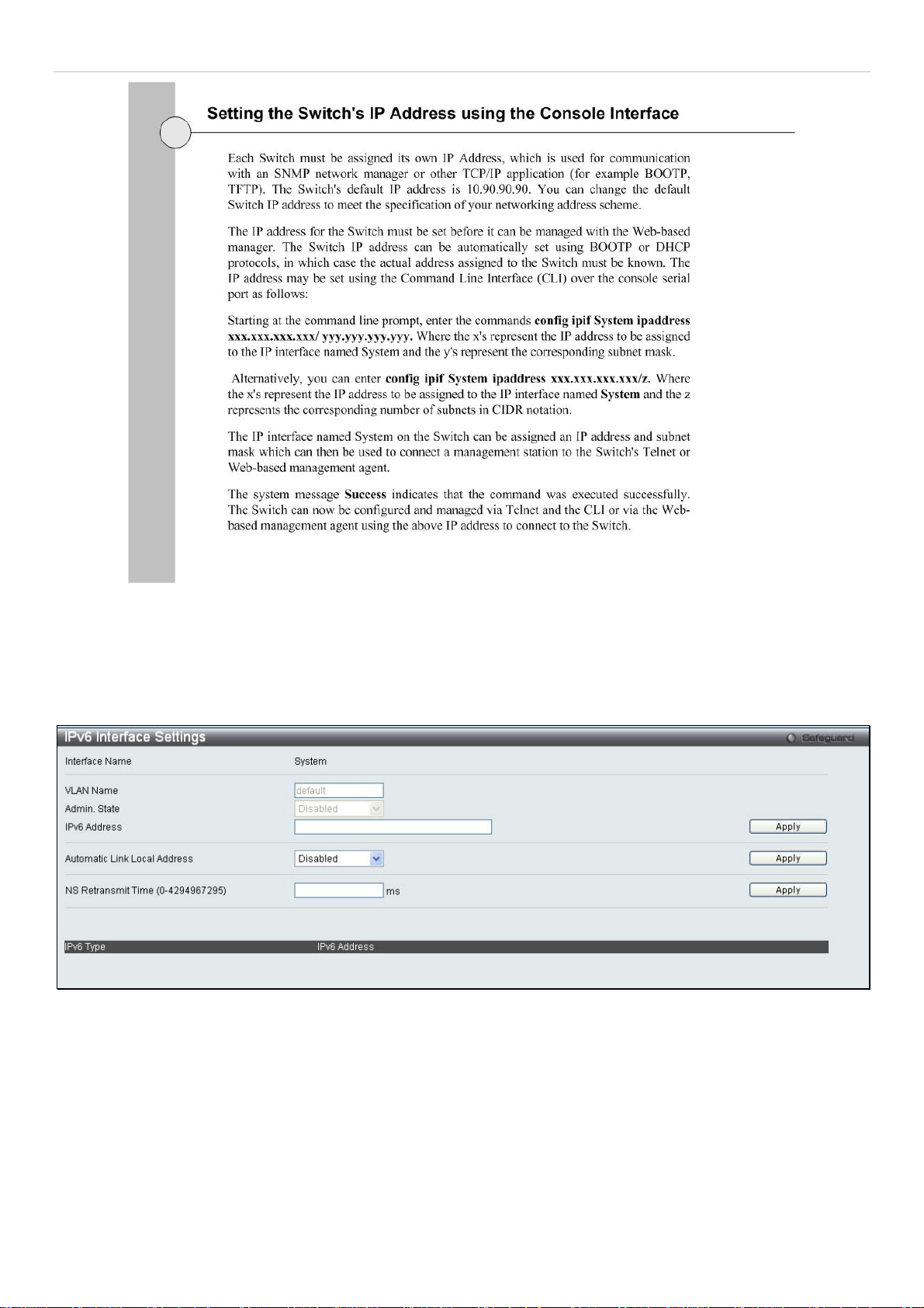
IPv6 Address Settings
Users can display the Switch’s current IPv6 interface settings.
To view the following window, click Configuration > IPv6 Interface Settings:
Figure 2 - 5. IPv6 Interface Settings window
To configure IPv6 interface settings, enter an IPv6 Address and click
the bottom of the window.
After making the desired changes, click the
The following parameters may be configured or viewed:
Apply
button.
16
. The new entry will appear in the table at
Apply
®
xStack
Parameter Description
DES-3200-10/18/28/28F Layer 2 Ethernet Managed Switch User Manual
Interface Name
VLAN Name
Admin. State
IPv6 Address
Automatic Link
Local Address
NS Retransmit
Time (0-
4294967295)
The name of the IPv6 interface being displayed or modified.
Display the VLAN name of the IPv6 interface.
Display the current administrator state.
Enter the IPv6 address of the interface to be modified.
Toggle between Enabled and Disabled. Enabling this is helpful when no external source of network
addressing information is available.
Enter a value between 0 and 4294967295. This is the neighbor solicitation’s retransmit timer in
milliseconds. The default is zero.
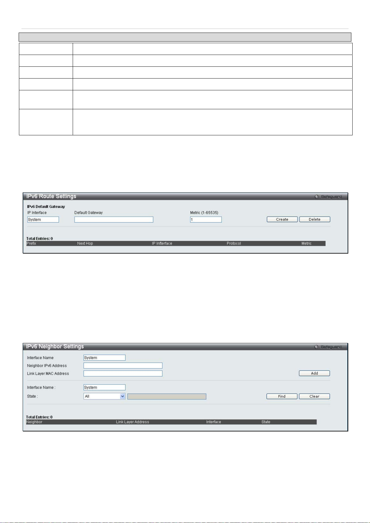
IPv6 Route Settings
The user can configure the Switch’s IPv6 Route Table.
To view the following window, click Configuration > IPv6 Route Settings:
Figure 2 - 6. IPv6 Route Settings window
Enter an IP Interface, an IPv6 address in the Default Gateway field and then click the Create button. In addition, the
Metric can be entered between 1 and 65535. The new IPv6 route will be displayed in the table at the bottom of the
window.
IPv6 Neighbor Settings
The user can configure the Switch’s IPv6 neighbor settings. The Switch’s current IPv6 neighbor settings will be
displayed in the table at the bottom of this window.
To view the following window, click Configuration > IPv6 Neighbor Settings:
Figure 2 - 7. IPv6 Neighbor Settings window
Enter the Interface Name, Neighbor IPv6 Address, and the Link Layer MAC Address and then click the
To look for an IPv6 Neighbor Settings table entry, enter the Interface Name, select the desired State (All, Address, Static, or
Dynamic) in the middle section of this window, and then click the
To delete all the entries being displayed on the table at the bottom of this window, click the
The following parameters may be configured or viewed:
17
Find
button.
Clear
button.
Add
button.
®
xStack
Parameter Description
DES-3200-10/18/28/28F Layer 2 Ethernet Managed Switch User Manual
Interface Name
Neighbor IPv6
Address
Link Layer MAC
Address
State
Enter the name of the IPv6 neighbor. To search for all the current interfaces on the Switch, go to
the second Interface Name field in the middle part of the window, tick the All check box, and then
click the Find button.
Enter the neighbor IPv6 address.
Enter the link layer MAC address.
Use the drop-down menu to select All, Address, Static, or Dynamic.
Port Configuration
This section contains information for configuring various attributes and properties for individual physical ports,
including port speed and flow control.
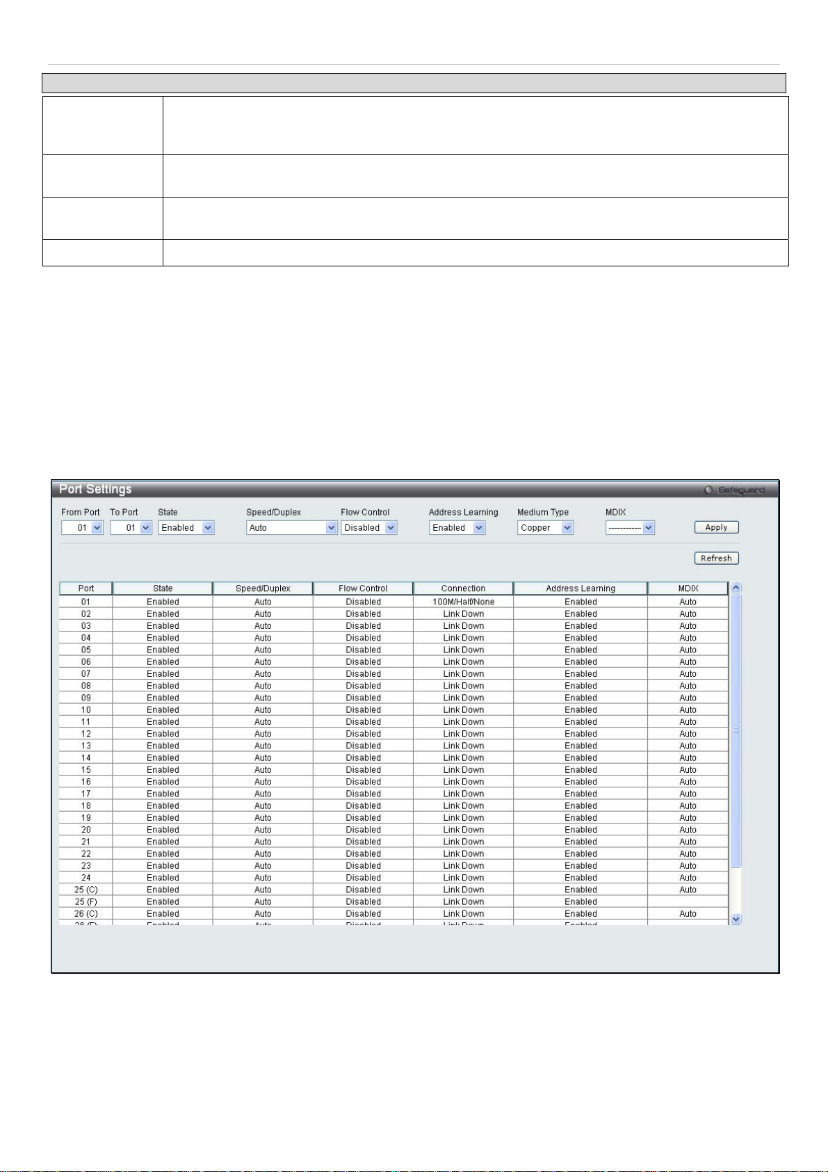
Port Settings
Various port settings, including State, Speed/Duplex, Flow Control, Address Learnng, Medium Type, and MDIX can be
configured on the Switch.
To view the following window, click Configuration > Port Configuration > Port Settings:
Figure 2 - 8. Port Settings window
To configure switch ports, choose the port or sequential range of ports using the From Port and To Port pull-down
menus. Use the remaining pull-down menus to configure the parameters described below:
18

®
xStack
DES-3200-10/18/28/28F Layer 2 Ethernet Managed Switch User Manual
Parameter Description
From Port/To
Use the pull-down menus to select the port or range of ports to be configured.
Port
State
Speed/Duplex
Flow Control
Toggle this field to either enable or disable a given port or group of ports.
Toggle the Speed/Duplex field to either select the speed and duplex/half-duplex state of the port.
Auto denotes auto-negotiation between 10 and 100 Mbps devices, in full- or half-duplex. The
Auto setting allows the port to automatically determine the fastest settings the device the port is
connected to can handle, and then to use those settings. The other options are Auto, 10M Half,
10M Full, 100M Half and 100M Full, 1000M Full_Master, 1000M Full_Slave and 1000M Full.
There is no automatic adjustment of port settings with any option other than Auto.
The Switch allows the user to configure two types of gigabit connections; 1000M/Full_M and
1000M/Full_S. Gigabit connections only support full duplex connections and take on certain
characteristics that are different from the other choices listed.
The 1000M Full_Master and 1000M Full_Slave parameters refer to connections running a
1000BASE-T cable for connection between the Switch port and other device capable of a gigabit
connection. The master setting (1000M Full_Master) will allow the port to advertise capabilities
related to duplex, speed and physical layer type. The master setting will also determine the
master and slave relationship between the two connected physical layers. This relationship is
necessary for establishing the timing control between the two physical layers. The timing control
is set on a master physical layer by a local source. The slave setting (1000M Full_Slave) uses
loop timing, where the timing comes from a data stream received from the master. If one
connection is set for 1000M Full_Master, the other side of the connection must be set for 1000M
Full_Slave. Any other configuration will result in a link down status for both ports.
Displays the flow control scheme used for the various port configurations. Ports configured for
full-duplex use 802.3x flow control, half-duplex ports use backpressure flow control, and Auto
ports use an automatic selection of the two. The default is Disabled.
Address
Learning
Medium Type
When Enabled, destination and source MAC addresses are automatically listed in the forwarding
table. The default setting is Enabled.
This applies only to the Combo ports. If configuring the Combo ports this defines the type of
transport medium used. SFP ports should be set at Fiber and the Combo 1000BASE-T ports
should be set at Copper.
MDIX
This can be specified as Auto, Normal, or Cross. In Normal state, the port is in MDIX mode and
can be connected to a PC NIC using a straight cable. If it is in Cross state, the port is in MDI
mode, and can be connected to a port (in MDIX mode) on another switch through a straight
cable.
Click Apply to implement the new settings on the Switch.
19
®
xStack
DES-3200-10/18/28/28F Layer 2 Ethernet Managed Switch User Manual
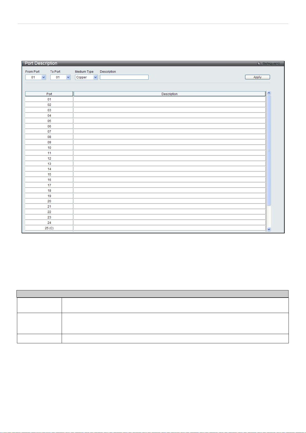
Port Description Settings
The Switch supports a port description feature where the user may name various ports on the Switch.
To view the following window, click Configuration > Port Configuration > Port Description Settings:
Figure 2 - 9. Port Description Settings window
Use the From Port and To Port pull-down menus to choose a port or range of ports to describe, and then enter a
description of the port(s).
The Medium Type applies only to the Combo ports. If configuring the Combo ports this defines the type of transport
medium used. SFP ports should be nominated Fiber and the Combo 1000BASE-T ports should be nominated Copper.
The result will be displayed in the appropriate switch port number slot (C for copper ports and F for fiber ports).
The following parameters can be configured:
Parameter Description
From Port/To
Port
Medium Type
Description
Click Apply to implement the new settings on the Switch.
Use the pull-down menus to select the port or range of ports to be configured.
This only applies to the Combo ports. If configuring the Combo ports, this defines the type of
transport medium used. SFP ports should be set at Fiber and the Combo 1000BASE-T ports
should be set at Copper.
The description of the the ports.
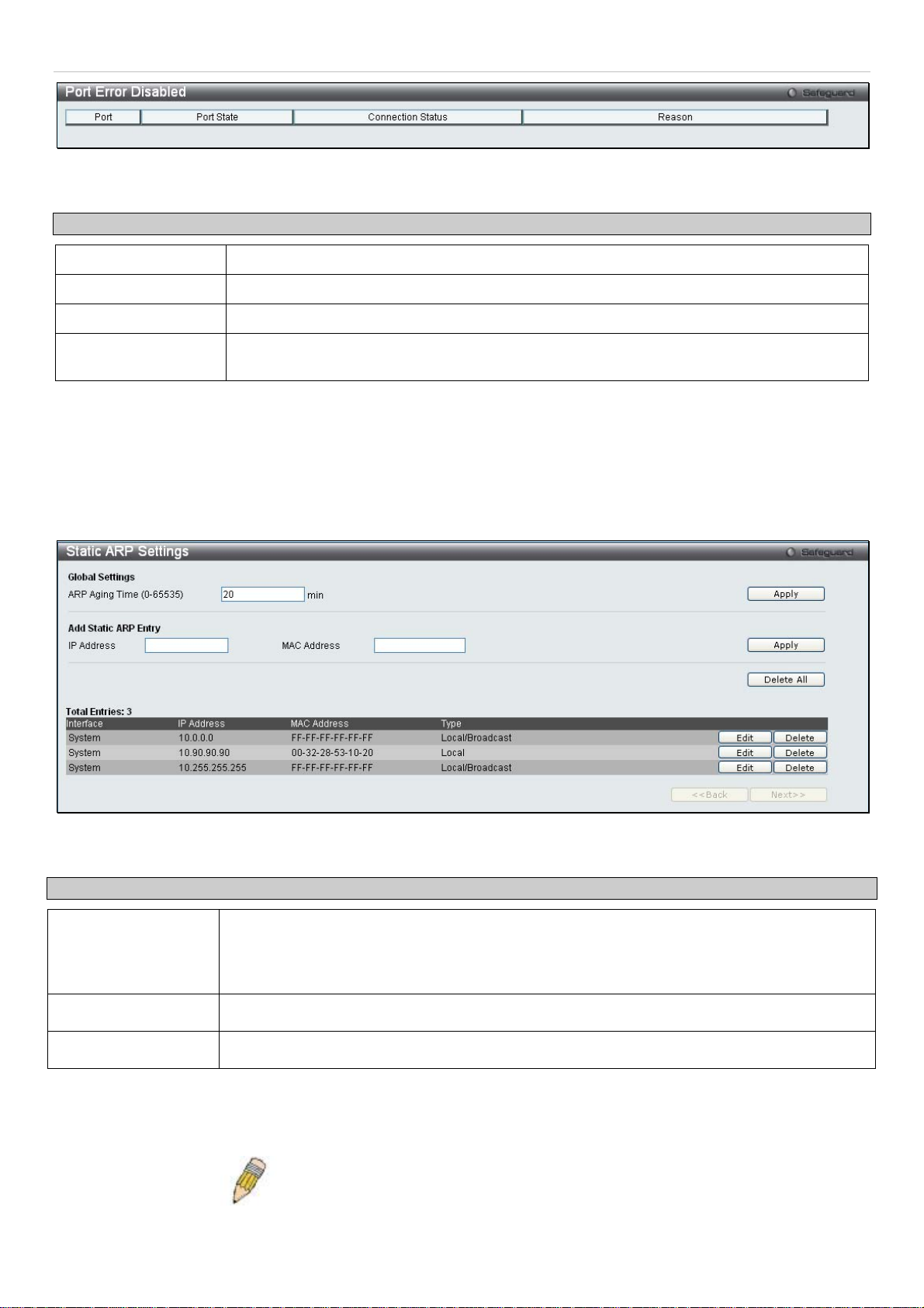
Port Error Disabled
The following window will display information about ports that have had their connection status disabled for reasons
such as STP loopback detection or link down status.
To view this window, click Configuration > Port Configuration > Port Error Disabled:
20
®
xStack
The following parameters are displayed:
Parameter Description
DES-3200-10/18/28/28F Layer 2 Ethernet Managed Switch User Manual
Figure 2 - 10. Port Error Disabled window
Port
Port State
Connection Status
Reason
Displays the port that has been error disabled.
Describes the current running state of the port, whether Enabled or Disabled.
This field will read the uplink status of the individual ports, whether Enabled or Disabled.
Describes the reason why the port has been error-disabled, such as a STP loopback
occurrence.
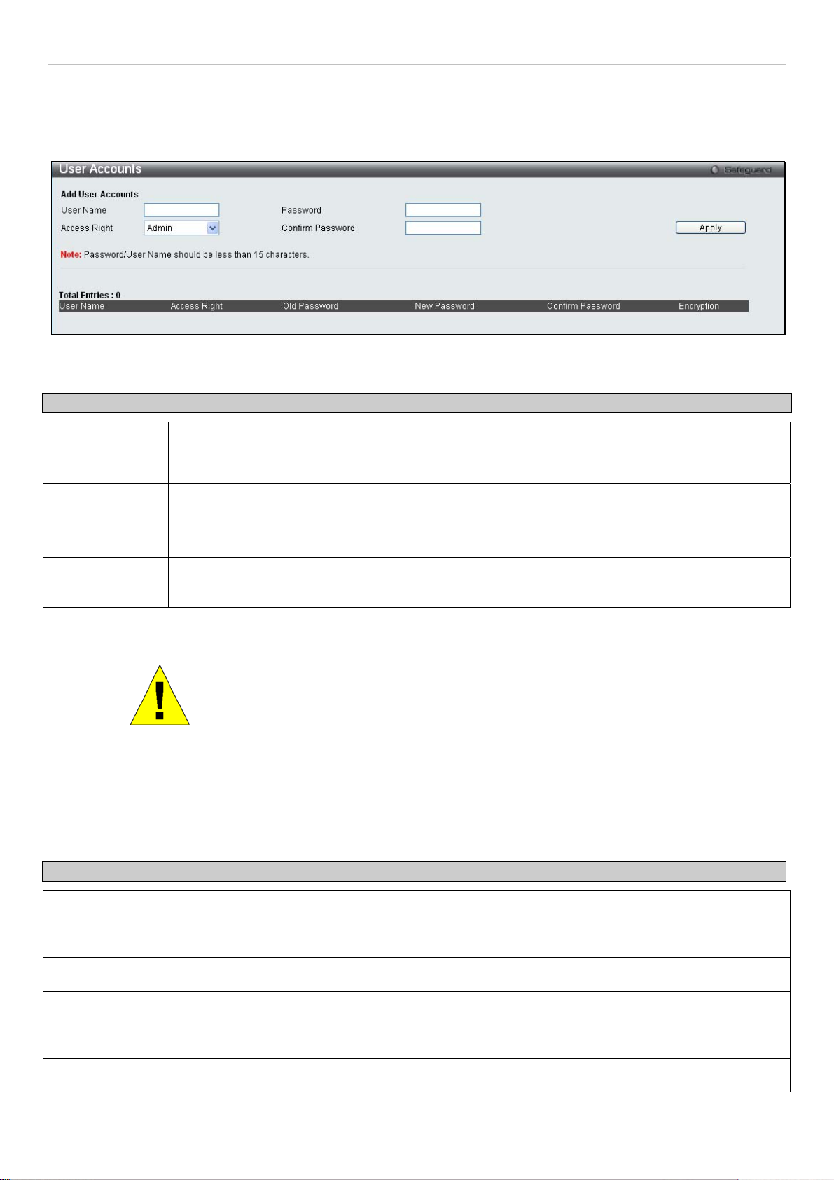
Static ARP Settings
The Address Resolution Protocol (ARP) is a TCP/IP protocol that converts IP addresses into physical addresses. This
table allows network managers to view, define, modify and delete ARP information for specific devices. Static entries
can be defined in the ARP Table. When static entries are defined, a permanent entry is entered and is used to
translate IP address to MAC addresses.
To view this window, click Configuration > Static ARP Settings
Figure 2 - 11. Static ARP Settings window
The following fields can be set:
Parameter Description
ARP Aging Time
(0-65535)
IP Address
MAC Address
After entering the IP Address and MAC Address of the Static ARP entry, click Apply to implement the new entry. To
completely clear the Static ARP Settings, click the Delete All button. To modify a static ARP entry, click the
corresponding Edit button in the table. To delete a static ARP entry, click the corresponding Delete button in the table.
The user may globally set the maximum amount of time, in seconds, that an Address
Resolution Protocol (ARP) entry can remain in the Switch’s ARP table, without being
accessed, before it is dropped from the table. The value may be set in the range of 0 to
65535 seconds, with a default setting of 20 seconds.
The IP address of the ARP entry.
The MAC address of the ARP entry.
NOTE: The Switch supports up to 255 static ARP entries.
21
®
xStack
DES-3200-10/18/28/28F Layer 2 Ethernet Managed Switch User Manual
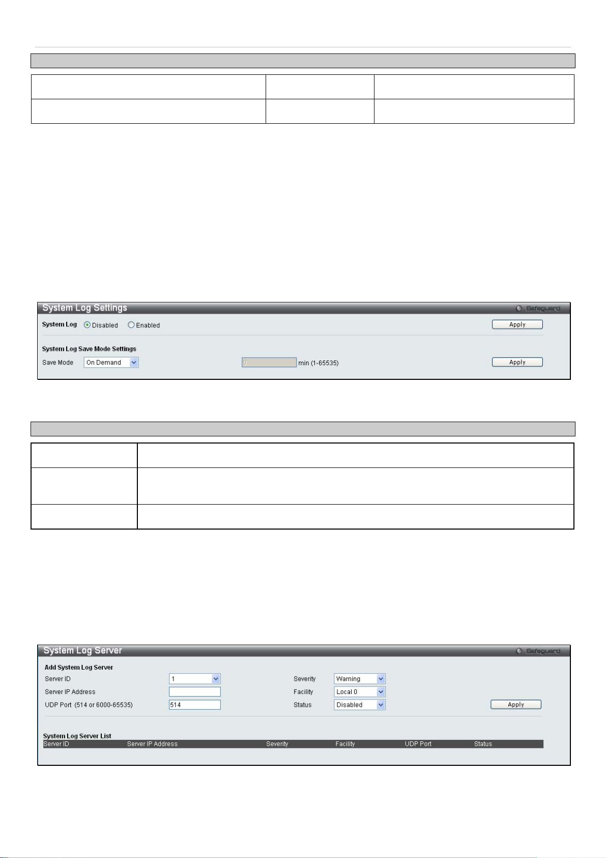
User Accounts
Use this window to control user privileges, create new users, and view existing User Accounts.
To view this window, click Configuration > User Accounts:
Figure 2 - 12. User Accounts window
The following fields can be set:
Parameter Description
User Name
Password
Access Right
Confirm
Password
To add a new user, enter the appropriate information and click Apply. To modify or delete an existing user, click on
the Edit button for that user.
The name of the user, an alphanumeric string of up to 15 characters.
Enter a password for the new user.
There are two levels of user privileges, Admin and User. Some features and selections available
to users with Admin privileges may not be available to those with User level privileges.
(Table 2 - 1 below summarizes Admin and User level privileges)
Retype the new password.
NOTICE: In case of lost passwords or password corruption, please refer to the
“Password Recovery Procedure” Appendix in the DES-3200-10/18/28/28F CLI
Reference Manual which will guide you through the steps necessary to resolve
this issue.
Admin and User Privileges
There are two levels of user privileges, Admin and User. Some menu selections available to users with Admin
privileges may not be available to those with User privileges.
The following table summarizes the Admin and User privileges:
Management Admin User
Configuration Yes Read-only
Network Monitoring Yes Read-only
Community Strings and Trap Stations Yes Read-only
Update Firmware and Configuration Files Yes No
System Utilities Yes No
Factory Reset Yes No
22
®
xStack
User Account Management
Add/Update/Delete User Accounts Yes No
View User Accounts Yes No
DES-3200-10/18/28/28F Layer 2 Ethernet Managed Switch User Manual
Table 2 - 1. Admin and User Privileges
System Log Configuration
This section contains information for configuring various attributes and properties for System Log Configurations,
including System Log Settings and System Log Host.
System Log Settings
This window allows the user to enable or disable the System Log and specify the System Log Save Mode Settings.
To configure the system log settings, click Configuration > System Log Configuration > System Log Settings
Figure 2 - 13. System Log Settings window
The following parameters can be set:
Parameter Description
System Log
Save Mode
min (1-65535)
To modify the system log settings on this window, enter the appropriate information and click Apply.
Use the radio buttons to either enable or disable the system log feature.
Use this drop-down menu to choose the method that will trigger a log entry. Choose among
On Demand, Time Interval, and Log Trigger.
Enter a time interval, in minutes, for which a log entry is to be made.
System Log Server
The Switch can send Syslog messages to up to four designated servers using the System Log Server.
To configure the system log settings, click Configuration > System Log Configuration > System Log Server:
The following parameters can be set:
Figure 2 - 14. System Log Server window
23

®
xStack
DES-3200-10/18/28/28F Layer 2 Ethernet Managed Switch User Manual
Parameter Description
Server ID
Severity
Server IP Address
Facility
Syslog server settings index (1-4).
This drop-down menu allows you to select the level of messages that will be sent. The options
are Warning, Informational, and All.
The IP address of the Syslog server.
Some of the operating system daemons and processes have been assigned Facility values.
Processes and daemons that have not been explicitly assigned a Facility may use any of the
"local use" facilities or they may use the "user-level" Facility. Those Facilities that have been
designated are shown in the following: Bold font indicates the facility values that the Switch is
currently employing.
Numerical Facility Code Numerical Facility Code
0
1
2
3
4
5
7
8
9
10
11
kernel messages
user-level messages
mail system
system daemons
security/authorization messages
messages generated internally by
syslog line printer subsystem
network news subsystem
UUCP subsystem
clock daemon
security/authorization messages
FTP daemon
12
13
14
15
16
17
18
19
20
21
22
23
NTP subsystem
log audit
log alert
clock daemon
local use 0 (local0)
local use 1 (local1)
local use 2 (local2)
local use 3 (local3)
local use 4 (local4)
local use 5 (local5)
local use 6 (local6)
local use 7 (local7)
UDP Port
Type the UDP port number used for sending Syslog messages. The default is 514.
(514 or 6000-65535)
Status
Choose Enabled or Disabled to activate or deactivate.
To add a new entry, enter the appropriate information and click Apply.
24
®
xStack
DES-3200-10/18/28/28F Layer 2 Ethernet Managed Switch User Manual
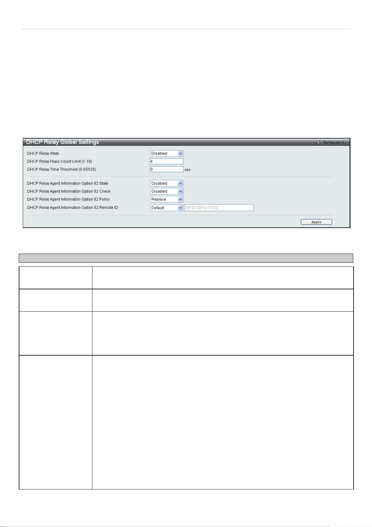
DHCP Relay
The relay hops count limit allows the maximum number of hops (routers) that the DHCP messages can be relayed
through to be set. If a packet’s hop count is equal to or more than the hop count limit, the packet is dropped. The
range is between 1 and 16 hops, with a default value of 4. The relay time threshold sets the minimum time (in seconds)
that the Switch will wait before forwarding a BOOTREQUEST packet. If the value in the seconds field of the packet is
less than the relay time threshold, the packet will be dropped. The range is between 0 and 65,535 seconds, with a
default value of 0 seconds.
DHCP Relay Global Settings
To enable and configure DHCP Relay Global Settings on the Switch, click Configuration > DHCP Relay > DHCP
Relay Global Settings:
Figure 2 - 15. DHCP Relay Global Settings window
The following fields can be set:
Parameter Description
DHCP Relay State
DHCP Relay Hops
Count Limit (1-16)
DHCP Relay Time
Threshold (0-65535)
DHCP Relay Agent
Information Option 82
State
This field can be toggled between Enabled and Disabled using the pull-down menu. It is
used to enable or disable the DHCP Relay service on the Switch. The default is Disabled
This field allows an entry between 1 and 16 to define the maximum number of router hops
DHCP messages can be forwarded across. The default hop count is 4.
Allows an entry between 0 and 65535 seconds, and defines the maximum time limit for
routing a DHCP packet. If a value of 0 is entered, the Switch will not process the value in
the seconds field of the BOOTP or DHCP packet. If a non-zero value is entered, the Switch
will use that value, along with the hop count to determine whether to forward a given
BOOTP or DHCP packet.
This field can be toggled between Enabled and Disabled using the pull-down menu. It is
used to enable or disable the DHCP Agent Information Option 82 on the Switch. The default
is Disabled.
Enabled – When this field is toggled to Enabled the relay agent will insert and remove
DHCP relay information (option 82 field) in messages between DHCP servers and clients.
When the relay agent receives the DHCP request, it adds the option 82 information, and the
IP address of the relay agent (if the relay agent is configured), to the packet. Once the
option 82 information has been added to the packet it is sent on to the DHCP server. When
the DHCP server receives the packet, if the server is capable of option 82, it can implement
policies like restricting the number of IP addresses that can be assigned to a single remote
ID or circuit ID. Then the DHCP server echoes the option 82 field in the DHCP reply. The
DHCP server unicasts the reply to the back to the relay agent if the request was relayed to
the server by the relay agent. The switch verifies that it originally inserted the option 82
data. Finally, the relay agent removes the option 82 field and forwards the packet to the
switch port that connects to the DHCP client that sent the DHCP request.
Disabled - If the field is toggled to Disabled the relay agent will not insert and remove DHCP
relay information (option 82 field) in messages between DHCP servers and clients, and the
25

®
xStack
DES-3200-10/18/28/28F Layer 2 Ethernet Managed Switch User Manual
check and policy settings will have no effect.
DHCP Relay Agent
Information Option 82
Check
DHCP Relay Agent
Information Option 82
Policy
DHCP Relay Agent
Information Option 82
Remote ID
This field can be toggled between Enabled and Disabled using the pull-down menu. It is
used to enable or disable the Switches ability to check the validity of the packet’s option 82
field.
Enabled – When the field is toggled to Enable, the relay agent will check the validity of the
packet’s option 82 field. If the switch receives a packet that contains the option-82 field from
a DHCP client, the switch drops the packet because it is invalid. In packets received from
DHCP servers, the relay agent will drop invalid messages.
Disabled - When the field is toggled to Disabled, the relay agent will not check the validity of
the packet’s option 82 field.
This field can be toggled between Replace, Drop, and Keep by using the pull-down menu.
It is used to set the Switches policy for handling packets when the DHCP Agent Information
Option 82 Check is set to Disabled. The default is Replace.
Replace - The option 82 field will be replaced if the option 82 field already exists in the
packet received from the DHCP client.
Drop - The packet will be dropped if the option 82 field already exists in the packet received
from the DHCP client.
Keep -The option 82 field will be retained if the option 82 field already exists in the packet
received from the DHCP client.
This field is for you to enter the remote ID. Tick Default to use the Switch’s system MAC
address as the remote ID.
Click Apply to implement any changes that have been made.
NOTE: If the Switch receives a packet that contains the option-82 field from a DHCP
client and the information-checking feature is enabled, the switch drops the packet
because it is invalid. However, in some instances, you might configure a client with the
option-82 field. In this situation, you should disable the information-check feature so
that the switch does not remove the option-82 field from the packet. You can configure
the action that the switch takes when it receives a packet with existing option-82
information by configuring the DHCP Agent Information Option 82 Policy.
The Implementation of DHCP Information Option 82 on the Switch
The config dhcp_relay option_82 command configures the DHCP relay agent information option 82 setting of the
switch. The formats for the circuit ID sub-option and the remote ID sub-option are as follows:
NOTE: For the circuit ID sub-option of a standalone switch, the module field is always
zero.
26

®
xStack
DES-3200-10/18/28/28F Layer 2 Ethernet Managed Switch User Manual
Circuit ID sub-option format:
a. b. c. d. e. f. g.
1 6 0 4 VLAN Module Port
1 byte 1 byte 1 byte 1 byte 2 bytes 1 byte 1 byte
a. Sub-option type
b. Length
c. Circuit ID type
d. Length
e. VLAN: the incoming VLAN ID of DHCP client packet.
f. Module: For a standalone switch, the Module is always 0; For a stackable switch, the Module is the
Unit ID.
g. Port: The incoming port number of DHCP client packet, port number starts from 1.
Remote ID sub-option format: (default)
1. 2. 3. 4. 5.
2 8 0 6 MAC address
1 byte 1 byte 1 byte 1 byte 6 bytes
1. Sub-option type
2. Length
3. Remote ID type
4. Length
5. MAC address: The Switch’s system MAC address.
Remote ID sub-option format:(for user-configured string)
1. 2. 3. 4. 5.
2 N+2 1 N ASCII Remote ID String (up to 127 characters)
1 byte 1 byte 1 byte 1 byte N bytes
1. Sub-option type
2. Length
3. Remote ID type
4. Length
5. User configured Remote-ID
Figure 2 - 16. Circuit ID and Remote ID Sub-option Format
27
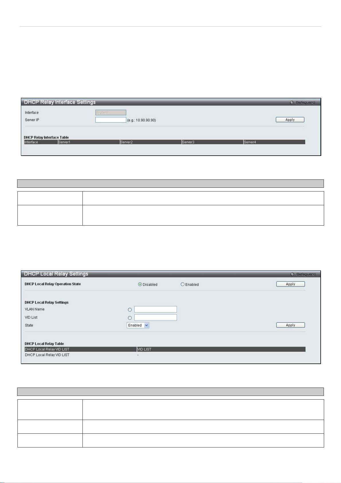
®
xStack
DES-3200-10/18/28/28F Layer 2 Ethernet Managed Switch User Manual
DHCP Relay Interface Settings
This window allows the user to set up a server, by IP address, for relaying DHCP/ BOOTP information to the Switch.
The user may enter a previously configured IP interface on the Switch that will be connected directly to the DHCP
server using the following window. Properly configured settings will be displayed in the DHCP Relay Interface Table at
the bottom of the following window. The user may add up to four server IP’s per IP interface on the Switch.
To enable and configure DHCP Relay Global Settings on the Switch, click Configuration > DHCP Relay > DHCP
Relay Interface Settings:
Figure 2 - 17. DHCP Relay Interface Settings window
The following parameters may be configured or viewed.
Parameter Description
Interface
Server IP
The IP interface on the Switch that will be connected directly to the Server.
Enter the IP address of the DHCP server. Up to four server IPs can be configured per IP
Interface
DHCP Local Relay Settings
This function on the Switch allows configuration of the DHCP local relay for VLAN.
To view this window, click Configuration > DHCP Local Relay> DHCP Local Relay Settings:
Figure 2 - 18. DHCP Local Relay Settings window
The following parameters may be configured.
Parameter Description
DHCP Local Relay
Operation State
VLAN Name
VID List
This is used to enable or disable DHCP Local Relay service on the Switch. The default is
Disabled.
Enter a name of the VLAN to be enabled by DHCP local relay.
Enter a VLAN ID to be enabled by DHCP local relay.
28
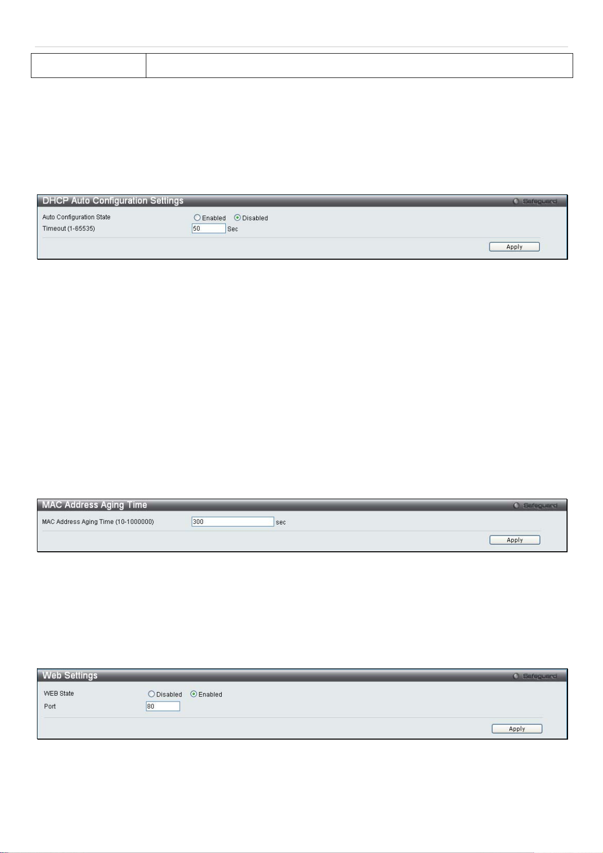
xStack
®
DES-3200-10/18/28/28F Layer 2 Ethernet Managed Switch User Manual
State
This is used to enable or disable the DHCP local relay for the specified VLAN.
DHCP Auto Configuration Settings
The DHCP automatic configuration function on the Switch will load a previously saved configuration file for current use.
When DHCP auto configuration is Enabled on the Switch, the DHCP reply will contain a configuration file and path
name. It will then request the file from the TFTP server specified in the reply.
To view this window, click Configuration > DHCP Auto Configuration Settings:
Figure 2 - 19. DHCP Auto Configuration Settings window
When DHCP automatic configuration is Enabled, the Switch becomes a DHCP client automatically after rebooting.
The DHCP server must have the TFTP server IP address and configuration file name, and be configured to deliver
this information in the data field of the DHCP reply packet. The TFTP server must be running and have the requested
configuration file in its base directory when the request is received from the Switch. Consult the DHCP server and
TFTP server software instructions for information on loading a configuration file.
If the Switch is unable to complete the automatic configuration process, the previously saved local configuration file
present in Switch memory will be loaded.
MAC Address Aging Time
This table specifies the length of time a learned MAC Address will remain in the forwarding table without being
accessed (that is, how long a learned MAC Address is allowed to remain idle). To change this, enter a value
representing the MAC address age-out time in seconds. The MAC Address Aging Time can be set to any value
between 10 and 1,000,000 seconds. The default setting is 300 seconds.
To access this window, click Configuration > MAC Address Aging Time:
Figure 2 - 20. MAC Address Aging Time window
Web Settings
Web-based management is Enabled by default. If you choose to disable this by selecting Disabled, you will lose the
ability to configure the system through the Web interface as soon as these settings are applied. The TCP ports are
numbered between 1 and 65535. The "well-known" TCP port for the Web protocol is 80.
To access this window, click Configuration > Web Settings:
Figure 2 - 21. Web Settings window
29
 Loading...