


PARTS & SERVICE MANUAL
FOR THE BUILT IN FIREPLACE
MODEL NUMBERS:
BF33ST/DX
BF39ST/DX
BF45ST/DX

TABLE OF CONTENTS
OPERATION |
PAGE 1 |
VOLTAGE SELECTOR SWITCH LOCATION |
PAGE 3 |
PARTS LIST DRAWING |
PAGE 4 |
PARTS LIST |
PAGE 5 |
WIRING DIAGRAM – LOWER SECTION |
PAGE 7 |
WIRING DIAGRAM – UPPER SECTION |
PAGE 8 |
WIRING DIAGRAM – SCHEMATIC |
PAGE 9 |
LIGHT BULB REPLACEMENT |
PAGE 10 |
MAIN ON/OFF SWITCH REPLACEMENT |
PAGE 11 |
HEATER ON/OFF SWITCH REPLACEMENT |
PAGE 12 |
FLAME MOTOR/FLAME ROD REPLACEMENT |
PAGE 13 |
VOLTAGE SELECTOR SWITCH REPLACEMENT |
|
(UNIT IS PERMENANTLY INSTALLED IN WALL) |
|
BF33ST, BF33DX |
PAGE 15 |
BF39ST, BF39DX, BF45ST, BF45DX |
PAGE 17 |
VOLTAGE SELECTOR SWITCH REPLACEMENT |
PAGE 19 |
(UNIT CAN BE REMOVED FROM WALL) |
|
HEATING ELEMENTS REPLACEMENT |
PAGE 20 |
(UNIT IS PERMENANTLY INSTALLED IN WALL) |
|
HEATING ELEMENTS REPLACEMENT |
PAGE 21 |
(UNIT CAN BE REMOVED FROM WALL) |
|
BLOWER MOTOR/BLOWER REPLACEMENT |
|
(UNIT IS PERMENANTLY INSTALLED IN WALL) |
|
BF33ST, BF33DX |
PAGE 22 |
BF39ST, BF39DX, BF45ST, BF45DX |
PAGE 24 |

BLOWER MOTOR/BLOWER REPLACEMENT |
PAGE 25 |
(UNIT CAN BE REMOVED FROM WALL) |
|
TEMPERATURE LIMIT SWITCH REPLACEMENT |
|
(UNIT IS PERMENANTLY INSTALLED IN WALL) |
|
BF33ST, BF33DX |
PAGE 26 |
BF39ST, BF39DX, BF45ST, BF45DX |
PAGE 28 |
TEMPERATURE LIMIT SWITCH REPLACEMENT |
PAGE 30 |
(UNIT CAN BE REMOVED FROM WALL) |
|
REMOTE CONTROL KIT REPLACEMENT |
PAGE 31 |
BF33ST, BF33DX, BF39ST, BF39DX, BF45ST, BF45DX
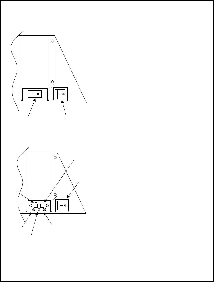
OPERATION
MAIN POWER HEATER CONTROL SWITCH
SWITCH
FIGURE 1
OFF
SWITCH
ON
SWITCH
LEVEL 3 LEVEL 1 INDICATOR
INDICATOR
LEVEL 2
INDICATOR
FIGURE 2
MANUAL CONTROLS (WITHOUT REMOTE OPTION)
The fireplace can be controlled by the manual switches located on the fireplace (FIGURE 1).
Main Power Switch
Main ON/OFF switch, activates the flame effect.
Heater Control Switch
Heater ON/OFF switch, activates heater to the high level.
MANUAL CONTROLS (WITH REMOTE OPTION)
The fireplace can also be controlled in a similar manner to the remote control with the manual switches located on the fireplace (FIGURE 2). (refer to initialization instructions on page 2)
Main Power Switch
Main ON/OFF switch supplies power to the circuit board. When the Main ON/OFF switch is switched to the ON position the Level 1 indicator light will flash.
On Switch
1.Pressing once on the remote control board “ON SWITCH” activates the Level 1 function.
Level 1: The flame effect is turned on and the first red indicator light is activated.
2.Pressing twice on the remote control board “ON SWITCH” activates the Level 2 function.
Level 2: The flame effect remains on, the heater is activated to the low heat setting, and
the first and second red indicator lights are activated.
3.Pressing three times on the remote control board
“ON SWITCH” activates the Level 3 function. Level 3: The flame effect remains on, the heater is set to the high heat setting, and all three red indicator lights are activated.
Off Switch
Pressing this button ONCE will turn the unit OFF.
1
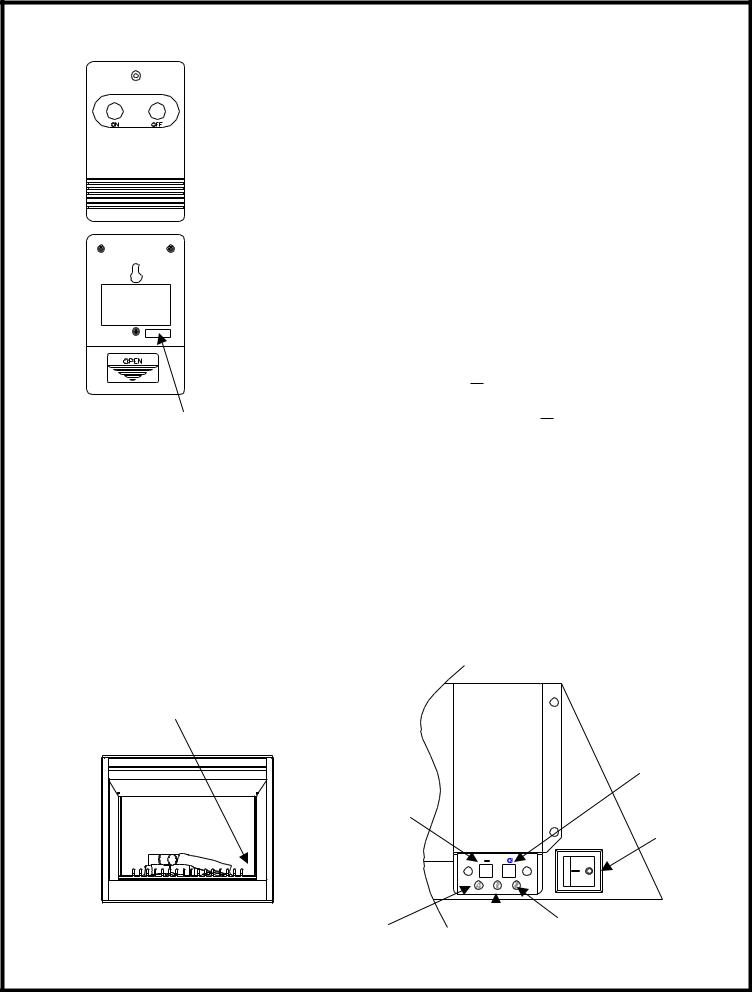
BF33ST, BF33DX, BF39ST, BF39DX, BF45ST, BF45DX
Frequency
Code
FIGURE 3
REMOTE CONTROL
The remote control has a range of approximately 50ft. (15.25m). It does not have to be pointed at the fireplace and can pass through most obstacles (including walls). It is supplied with one of 243 independent frequencies to prevent interference with other units. The frequency designation is indicated on the back of the transmitter (FIGURE 3).
Remote Control Initialization
This procedure is required every time there is a loss of power to the remote control in the fireplace (i.e. power failure, breaker tripped, main power switch is turned off)
1.Ensure that power is supplied through main service panel.
2.Access the manual controls, (remove glass doors if applicable) pull the right hand steel curtain to the side of the unit. (FIGURE 4)
3.Locate manual controls refer to FIGURE 5.
4.Activate main power switch, (“ ” position is “ON”, “ ” position is “OFF”) red Level 1 indicator light will flash.
5.Press and hold the ON switch marked “ ” for five seconds.
The red Level 2 indicator light will flash.
6.Press the ON button located on the remote control transmitter (FIGURE 3). This will synchronize the remote control transmitter and receiver.
Remote Control Usage
The remote control operates the fireplace levels sequentially. The level is increased every time the ON button on the transmitter is pressed. The fireplace can be turned off at any point by pressing the OFF button on the remote control transmitter.
Level 1: The flame effect is turned on and the first red indicator light is activated. Level 2: The flame effect remains on, the heater is activated to the low heat setting, and the first and second red indicator lights are activated.
Level 3: The flame effect remains on, the heater is set to the high heat setting, and all three red indicator lights are activated.
MANUAL CONTROLS
Off Switch
On Switch
Main Power
Switch
|
|
|
|
|
|
|
|
|
|
|
|
|
Level 3 Indicator |
|
|
FIGURE 4 |
Level 1 Indicator |
|
|
|
|||
|
|
|
|
|
|
||
|
Level 2 Indicator |
|
|
|
|||
|
|
|
FIGURE 5 |
||||
|
2 |
|
|
||||
|
|
|
|
|
|||
|
|
|
|
|
|||
BF33ST, BF33DX, BF39ST, BF39DX, BF45ST, BF45DX
RESETTING THE TEMPERTURE CUTOUT SWITCH
The heater on this fireplace is protected with a safety device to prevent overheating.
Should the heater overheat, an automatic cut out will turn the heater off and it will not come back on without being reset. It can be reset by switching the Main Power switch (FIGURE 1) to OFF and waiting 5 minutes before switching it to ON.
WALL MOUNTED CONTROLS
The fireplace can be installed with wall mounted controls. These controls include wall switches and thermostats. (see installation guide for details)
A. Wall Mounted Switches
This model may be installed such that a wall mounted switch activates the flame effect and a wall mounted heater switch activates the heater. A wall mounted switch can also be installed to operate the heater independent of the flame.
B. Wall Mounted Thermostat
This unit may be installed such that a wall mounted thermostat can adjust the heat temperature to your individual requirements. Turn the thermostat control clockwise all the way to turn on the heater. When the room reaches the desired temperature, turn the thermostat knob counter clockwise until you hear a click. Leave in this position to maintain the room temperature at this setting. For additional heat, turn the thermostat clockwise until you hear the click again and the heater will turn on. To turn the heater off, turn the thermostat counter clockwise all the way, and/or turn the manual heater switch on the unit to the OFF position.
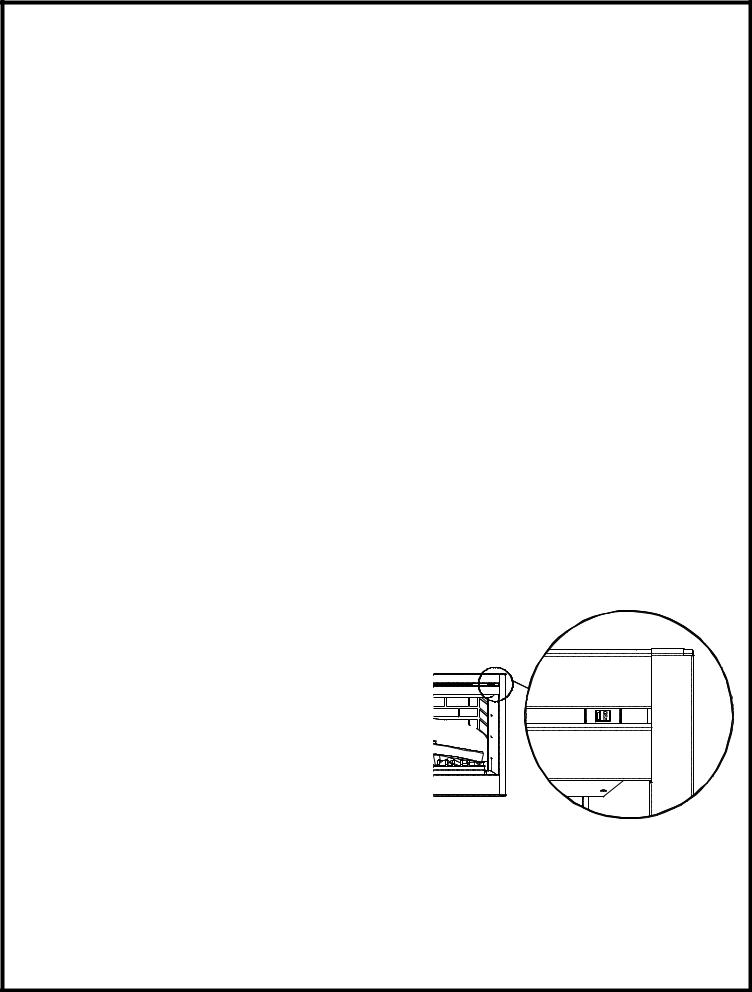
VOLTAGE SELECTOR SWITCH LOCATION
IMPORTANT:
Ensure that the incoming power supply voltage matches the setting of the voltage selector switch.
NOTE:
The voltage selector switch is located inside the exhaust panel on the top right hand corner (FIGURE 6).
CAUTION:
When changing the voltage selector switch from 240 volts to 120 volts ensure that the power supply is turned off.
NOTE:
Carefully insert a flat headed screwdriver inside the exhaust panel to change the switch from 240 volts (230 position) to 120 volts (115 position).
3

BF33ST, BF33DX, BF39ST, BF39DX, BF45ST, BF45DX |
|
|
|
8 |
7 |
5 |
6 |
|
|
|
9 |
12 |
|
|
|
13 |
|
|
11 |
|
|
|
|
|
|
|
10 |
|
|
|
15 |
3 |
|
|
|
|
|
|
14 |
1 |
|
|
|
|
|
|
2 |
|
|
|
4 |
17 |
|
|
16 |
|
|
|
|
18 |
|
|
|
4 |
|
|
|

BF33ST, BF33DX, BF39ST, BF39DX
REPLACEMENT PARTS
DIMPLEX BUILT IN FIREPLACE
REPLACEMENT PART |
BF33ST |
BF33DX |
|
1. |
LOG SET |
0438200300RP |
0438200300RP |
2. |
REFLECTOR ROD |
5900081000RP |
5900081000RP |
3. |
GROMMET |
8500000600RP |
8500000600RP |
4. |
FLICKER ASSEMBLY |
6901811200RP |
6901811200RP |
5. |
BLOWER ASSEMBLY |
5300110300RP |
5300110300RP |
6. |
BLOWER MOTOR |
5300110400RP |
5300110400RP |
7. |
HEATER ELEMENT |
2200510100RP |
2200510100RP |
8. |
CUTOUT |
2300200400RP |
2300200400RP |
9. |
VOLTAGE SELECTOR |
2500320100RP |
2500320100RP |
10.MAIN ON/OFF SWITCH |
2800070400RP |
2800070400RP |
|
11.HEATER SWITCH |
2800070700RP |
2800070700RP |
|
12.MIRROR SEMI-SILVERED |
5900161000RP |
5900161100RP |
|
13.EXTRUSION |
0438650200RP |
0438650200RP |
|
14.STEEL CURTAIN |
8800240403RP |
8800240403RP |
|
15.STEEL CURTAIN ROD |
8800250300RP |
8800250300RP |
|
16.LAMPHOLDER |
4200120700RP |
4200120700RP |
|
OPTIONAL ACCESSORIES |
|
|
|
17. REMOTE CONTROL KIT |
BFRC-KIT |
|
|
18. WALL THERMOSTAT |
TS901/TS901W |
|
|
REPLACEMENT PART |
BF39ST |
BF39DX |
|
1. |
LOG SET |
0438550200RP |
0438550200RP |
2. |
REFLECTOR ROD |
5900080900RP |
5900080900RP |
3. |
GROMMET |
8500000600RP |
8500000600RP |
4. |
FLICKER ASSEMBLY |
6901811200RP |
6901811200RP |
5. |
BLOWER ASSEMBLY |
5300110300RP |
5300110300RP |
6. |
BLOWER MOTOR |
5300110400RP |
5300110400RP |
7. |
HEATER ELEMENT |
2200510100RP |
2200510100RP |
8. |
CUTOUT |
2300200400RP |
2300200400RP |
9. |
VOLTAGE SELECTOR |
2500320100RP |
2500320100RP |
10.MAIN ON/OFF SWITCH |
2800070400RP |
2800070400RP |
|
11.HEATER SWITCH |
2800070700RP |
2800070700RP |
|
12.MIRROR SEMI-SILVERED |
5900160600RP |
5900160700RP |
|
13.EXTRUSION |
0438650100RP |
0438650100RP |
|
14.STEEL CURTAIN |
8800240103RP |
8800240103RP |
|
15.STEEL CURTAIN ROD |
8800250100RP |
8800250200RP |
|
16.LAMPHOLDER |
4200120700RP |
4200120700RP |
|
OPTIONAL ACCESSORIES |
|
|
|
17. REMOTE CONTROL KIT |
BFRC-KIT |
|
|
18. WALL THERMOSTAT |
TS901/TS901W |
|
|
5

BF45ST, BF45DX
REPLACEMENT PARTS
DIMPLEX BUILT IN FIREPLACE
REPLACEMENT PART |
BF45ST |
BF45DX |
|
1. |
LOG SET |
0438550200RP |
0438550200RP |
2. |
REFLECTOR ROD |
5900080900RP |
5900080900RP |
3. |
GROMMET |
8500000600RP |
8500000600RP |
4. |
FLICKER ASSEMBLY |
6901811200RP |
6901811200RP |
5. |
BLOWER ASSEMBLY |
5300110300RP |
5300110300RP |
6. |
BLOWER MOTOR |
5300110400RP |
5300110400RP |
7. |
HEATER ELEMENT |
2200510100RP |
2200510100RP |
8. |
CUTOUT |
2300200400RP |
2300200400RP |
9. |
VOLTAGE SELECTOR |
2500320100RP |
2500320100RP |
10.MAIN ON/OFF SWITCH |
2800070400RP |
2800070400RR |
|
11.HEATER SWITCH |
2800070700RP |
2800070700RP |
|
12.MIRROR SEMI-SILVERED |
5900160800RP |
5900160400RP |
|
13.EXTRUSION |
0438650100RP |
0438650100RP |
|
14.STEEL CURTAIN |
8800240203RP |
8800240203RP |
|
15.STEEL CURTAIN ROD |
8800250200RP |
8800250200RP |
|
16.LAMPHOLDER |
4200120700RP |
4200120700RP |
|
OPTIONAL ACCESSORIES |
|
|
|
17. REMOTE CONTROL KIT |
BFRC-KIT |
|
|
18. WALL THERMOSTAT |
TS901/TS901W |
|
|
6
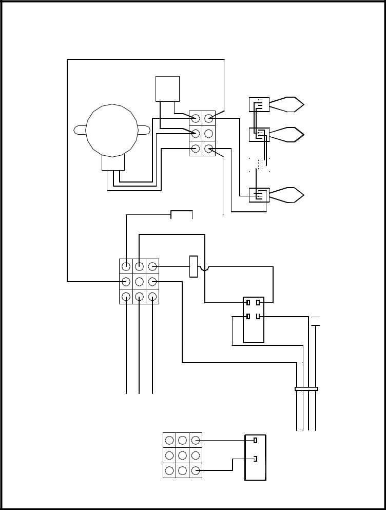
BF33ST, BF33DX, BF39ST, BF39DX, BF45ST, BF45DX
WIRING DIAGRAM - LOWER SECTION
FLICKER MOTOR
-CAPA
CITOR
BROWN WHITE BLACK
WHITE 


 BLUE WHITE
|
BLUE (3) |
MARR BLUE (4) |
|||
|
|
BLACK |
|
|
|
|
|
|
RED (1) |
MARR |
RED (2) |
|
|
|
|
||
WHITE |
TOPFROMORANGE |
TOPFROMRED TOPFROMBROWN |
|
|
(L1)BLACK |
HARNESSLOWER |
|
|
|||
|
|
|
|
|
BLACK |
|
|
|
WHITE (N) |
||
BYPASS |
RED |
|
|
HARNESS |
RED |
|
MAIN SWITCH |
|
4B |
1A |
5B |
2A |
 2 1
2 1
RED (L2)
 G
G
TIE-TWIST |
WHITE |
|
|
RED BLACK |
|
|
(N) |
GREEN |
HEATER |
(L1) |
(L2) |
SWITCH |
|
|
7
BF33ST, BF33DX, BF39ST, BF39DX, BF45ST, BF45DX
WIRING DIAGRAM - UPPER SECTION
|
-(CUT RED |
ORANGE |
BROWN |
|
|
|
|
|
WIRE) LONG OUT |
|
|
|
|
|
|
|
|
|
|
|
|
BLK |
|
|
|
5 |
3 |
1 |
|
|
|
|
|
6 |
4 |
2 |
|
|
|
|
|
|
|
|
YLW |
|
|
|
|
BLK |
|
YLW |
BLK |
BLK |
.BLW MOTOR |
|
|
|
|
|
|
BLK |
|
OUT-CUT |
WIRE) SHORT OUT-(CUT RED |
#2 ELEMENT |
|
#1 ELEMENT |
|
|
WHEEL BLOWER |
|
|
YLW |
|
BLK |
|
|
|
|
|
|
|
|
8 |
|
|
 Loading...