


.&("QJY¥ 3MP PTZ IP Camera
%8$ .PTZ336XW
User’s Manual 7FS04/20
#FGPSF JOTUBMMJOH BOE VTJOH UIF DBNFSB QMFBTF SFBE UIJT NBOVBM DBSFGVMMZ #F TVSF UP LFFQ JU IBOEZ GPS GVUVSF SFGFSFODF

4BGFUZ *OGPSNBUJPO
$"65*0/
3*4, 0' &-&$53*$ 4)0$, %0 /05 01&/
$"65*0/
50 3&%6$& 5)& 3*4, 0' &-&$53*$ 4)0$, %0 /05 3&.07& $07&3 03 #"$, /0 64&3 4&37*$&"#-& 1"354 */4*%& 3&'&3 4&37*$*/( 50 26"-*'*&% 4&37*$& 1&340//&-
8BSOJOH |
1SFDBVUJPO |
5IJT TZNCPM JOEJDBUFT UIBU EBOHFSPVT WPMUBHF |
5IJT FYDMBNBUJPO QPJOU TZNCPM JT JOUFOEFE UP BMFSU UIF |
DPOTJTUJOH B SJTL PG FMFDUSJD TIPDL JT QSFTFOU XJUIJO |
VTFS UP UIF QSFTFODF PG JNQPSUBOU PQFSBUJOH BOE |
UIJT VOJU |
NBJOUFOBODF TFSWJDJOH JOTUSVDUJPOT JO UIF MJUFSBUVSF |
|
BDDPNQBOZJOH UIF BQQMJBODF |
8"3/*/( |
1SFDBVUJPO |
5P QSFWFOU EBNBHF XIJDI NBZ SFTVMU JO GJSF PS FMFDUSJD TIPD |
0QFSBUJOH |
IB[BSE EP OPU FYQPTF UIJT BQQMJBODF UP SBJO PS NPJTUVSF |
t #FGPSF VTJOH NBLF TVSF QPXFS TVQQMZ BOE BMM PUIFS QBSUT BSF |
8"3/*/( |
QSPQFSMZ DPOOFDUFE |
t 8IJMF PQFSBUJOH JG BOZ BCOPSNBM DPOEJUJPO PS NBMGVODUJPO |
1.#F TVSF UP VTF POMZ UIF TUBOEBSE BEBQUFS UIBU JT TQFDJGJFE J JT PCTFSWFE TUPQ VTJOH UIF DBNFSB JNNFEJBUFMZ BOE DPOUBDU UIF TQFDJGJDBUJPO TIFFU 6TJOH BOZ PUIFS BEBQUFS DPVME DBVT ZPVS EFBMFS
GJSF FMFDUSJDBM TIPDL PS EBNBHF UP UIF QSPEVDU )BOEMJOH
2.*ODPSSFDUMZ DPOOFDUJOH UIF QPXFS TVQQMZ PS SFQMBDJOH CBUUFSZ t %P OPU EJTBTTFNCMF PS UBNQFS XJUI QBSUT JOTJEF UIF DBNFSB NBZ DBVTF FYQMPTJPO GJSF FMFDUSJD TIPDL PS EBNBHF UP UI t %P OPU ESPQ UIF DBNFSB PS TVCKFDU JU UP TIPDL PS WJCSBUJPO BT QSPEVDU UIJT DBO EBNBHF UIF DBNFSB
t $MFBO UIF DMFBS EPNF DPWFS XJUI FYUSB DBSF 4DSBUDIFT BOE
3.%P OPU DPOOFDU NVMUJQMF DBNFSBT UP B TJOHMF BEBQUFS EVTU DBO SVJO UIF RVBMJUZ PG UIF DBNFSB JNBHF
&YDFFEJOH UIF DBQBDJUZ NBZ DBVTF FYDFTTJWF IFBU HFOFSBUJPO
PS GJSF *OTUBMMBUJPO BOE 4UPSBHF
4.4FDVSFMZ QMVH UIF QPXFS DPSE JOUP UIF QPXFS SFDFQUBDMF
*OTFDVSF DPOOFDUJPO NBZ DBVTF GJSF
5.8IFO JOTUBMMJOH UIF DBNFSB GBTUFO JU TFDVSFMZ BOE GJSNMZ
" GBMMJOH DBNFSB NBZ DBVTF QFSTPOBM JOKVSZ
6.%P OPU QMBDF DPOEVDUJWF PCKFDUT F H TDSFX ESJWFST DPJOT
NFUBM JUFNT FUD PS DPOUBJOFST GJMMFE XJUI XBUFS PO UPQ P
UIF DBNFSB %PJOH TP NBZ DBVTF QFSTPOBM JOKVSZ EVF UP GJSF FMFDUSJD TIPDL PS GBMMJOH PCKFDUT
7.%P OPU JOTUBMM UIF VOJU JO IVNJE EVTUZ PS TPPUZ MPDBUJPOT %PJOH TP NBZ DBVTF GJSF PS FMFDUSJD TIPDL
8.*G BOZ VOVTVBM TNFMMT PS TNPLF DPNF GSPN UIF VOJU TUPQ VTJOH UIF QSPEVDU *NNFEJBUFMZ EJTDPOOFDU UIF QPXFS TPSDF BOE DPOUBDU UIF TFSWJDF DFOUFS $POUJOVFE VTF JO TVDI B DPOEJUJPO NBZ DBVTF GJSF PS FMFDUSJD TIPDL
9.*G UIJT QSPEVDU GBJMT UP PQFSBUF OPSNBMMZ DPOUBDU UIF OFBSFTU TFSWJDF DFOUFS /FWFS EJTBTTFNCMF PS NPEJGZ UIJT QSPEVDU JO BOZ XBZ
10.8IFO DMFBOJOH EP OPU TQSBZ XBUFS EJSFDUMZ POUP QBSUT PG UIF QSPEVDU %PJOH TP NBZ DBVTF GJSF PS FMFDUSJD TIPDL
t %P OPU JOTUBMM UIF DBNFSB JO BSFBT PG FYUSFNF UFNQFSBUVSF
FYDFFEJOH UIF BMMPXFE SBOHF
t"WPJE JOTUBMMJOH JO IVNJE PS EVTUZ FOWJSPONFOUT
t"WPJE JOTUBMMJOH JO QMBDFT XIFSF SBEJBUJPO JT QSFTFOU
t"WPJE JOTUBMMJOH JO QMBDFT XIFSF UIFSF BSF TUSPOH NBHOFUJD GJFMET BOE FMFDUSJD TJHOBMT
t"WPJE JOTUBMMJOH JO QMBDFT XIFSF UIF DBNFSB XPVME CF TVCKFDU UP TUSPOH WJCSBUJPOT
t/FWFS FYQPTF UIF DBNFSB UP SBJO PS XBUFS

*NQPSUBOU 4BGFUZ *OTUSVDUJPOT
3FBE UIFTF JOTUSVDUJPOT "MM TBGFUZ BOE PQFSBUJOH JOTUSVDUJPOT TIPVME CF SFBE CFGPSF JOTUBMMBUJPO PS PQFSBUJPO
,FFQ UIFTF JOTUSVDUJPOT 5IF TBGFUZ PQFSBUJOH BOE VTF JOTUSVDUJPOT TIPVME CF SFUBJOFE GPS GVUVSF SFGFSFODF
)FFE BMM XBSOJOHT "MM XBSOJOHT PO UIF QSPEVDU BOE JO UIF PQFSBUJOH JOTUSVDUJPOT TIPVME CF BEIFSFE UP
'PMMPX BMM JOTUSVDUJPOT "MM PQFSBUJOH BOE VTF JOTUSVDUJPOT TIPVME CF GPMMPXFE
%P OPU VTF UIJT EFWJDF OFBS XBUFS 'PS FYBNQMF OFBS B CBUIUVC XBTI CPXM LJUDIFO TJOL MBVOESZ UVC JO B XFU CBTFNFOU OFBS B TXJNNJOH QPPM FUD
$MFBO POMZ XJUI ESZ DMPUI 6OQMVH UIJT QSPEVDU GSPN UIF XBMM PVUMFU CFGPSF DMFBOJOH %P OPU VTF MJRVJE DMFBOFST
%P OPU CMPDL BOZ WFOUJMBUJPO PQFOJOHT *OTUBMM JO BDDPSEBODF XJUI UIF NBOVGBDUVSFS T JOTUSVDUJPOT 4MPUT BOE PQFOJOHT JO UIF DBCJOFU BSF QSPWJEFE GPS WFOUJMBUJPO UP FOTVSF SFMJBCMF PQFSBUJPO PG UIF QSPEVDU BOE UP QSPUFDU JU GSPN PWFS IFBUJOH 5IF PQFOJOHT TIPVME OFWFS CF CMPDLFE CZ QMBDJOH UIF QSPEVDU PO CFE TPGB SVH PS PUIFS TJNJMBS TVSGBDFT 5IJT QSPEVDU TIPVME OPU CF QMBDFE JO B CVJMU JO JOTUBMMBUJPO TVDI BT B CPPLDBTF PS SBDL VOMFTT QSPQFS WFOUJMBUJPO JT QSPWJEFE BOE UIF NBOVGBDUVSFST JOTUSVDUJPOT IBWF CFFO BEIFSF UP
%P OPU JOTUBMM OFBS BOZ IFBU TPVSDFT TVDI BT SBEJBUPST IFBU SFHJTUFST PS PUIFS BQQBSBUVT JODMVEJOH BNQMJGJFST UIBU QSPEVDF IFBU
%P OPU EFGFBU UIF TBGFUZ QVSQPTF PG UIF QPMBSJ[FE PS HSPVOEJOH UZQF QMVH " QPMBSJ[FE QMVH IBT UXP CMBEFT XJUI
POF XJEFS UIBO UIF PUIFS " HSPVOEJOH UZQF QMVH IBT UXP CMBEFT BOE B UIJSE HSPVOEJOH QSPOH 5IF XJEF CMBEF PS UIF UIJSE QSPOH BSF QSPWJEFE GPS ZPVS TBGFUZ *G UIF QSPWJEFE QMVH EPFT OPU GJU JOUP ZPVS PVUMFU DPOTVMU BO
FMFDUSJDJBO GPS SFQMBDFNFOU
1SPUFDU UIF QPXFS DPSE GSPN CFJOH XBMLFE PO PS QJODIFE QBSUJDVMBSMZ BU QMVHT DPOWFOJFODF SFDFQUBDMFT BOE
UIF QPJOU XIFSF UIFZ FYJU GSPN UIF BQQBSBUVT
0OMZ VTF BUUBDINFOUT BDDFTTPSJFT TQFDJGJFE CZ UIF NBOVGBDUVSFS
6TF POMZ XJUI DBSU TUBOE USJQPE CSBDLFU PS UBCMF TQFDJGJFE CZ UIF NBOVGBDUVSFS PS TPME XJUI UIF BQQBSBUVT 8IFO B DBSU JT VTFE VTF DBVUJPO XIFO NPWJOH UIF DBSU BQQBSBUVT DPNCJOBUJPO UP BWPJE JOKVSZ GSPN UJQ PWFS
6OQMVH UIF BQQBSBUVT EVSJOH MJHIUOJOH TUPSNT PS XIFO VOVTFE GPS MPOH QFSJPET PG UJNF
3FGFS BMM TFSWJDJOH UP RVBMJGJFE TFSWJDF QFSTPOOFM 4FSWJDJOH JT SFRVJSFE XIFO UIF BQQBSBUVT IBT CFFO EBNBHFE JO BOZ XBZ TVDI BT QPXFS TVQQMZ DPSE PS QMVH JT EBNBHFE MJRVJE IBT CFFO TQJMMFE PS PCKFDUT IBWF GBMMFO JOUP UIF
BQQBSBUVT UIF BQQBSBUVT IBT CFFO FYQPTFE UP SBJO PS NPJTUVSF EPFT OPU PQFSBUF OPSNBMMZ PS IBT CFFO ESPQQFE
%JTQPTBM PG 0ME "QQMJBODFT
8IFO UIJT DSPTTFE PVU XIFFM CJO TZNCPM JT BUUBDIFE UP B QSPEVDU JU NFBOT UIF QSPEVDU JT DPWFSFE CZ UIF
&VSPQFBO %JSFDUJWF &$
"MM FMFDUSJDBM BOE FMFDUSPOJD QSPEVDUT TIPVME CF EJTQPTFE PG TFQBSBUFMZ GPSN UIF NVOJDJQBM XBTUF TUSFBN iO BDDPSEBODF UP MBXT EFTJHOBUFE CZ UIF HPWFSONFOU PS UIF MPDBM BVUIPSJUJFT
5IF DPSSFDU EJTQPTBM PG ZPVS PME BQQMJBODF XJMM IFMQ QSFWFOU QPUFOUJBM OFHBUJWF DPOTFRVFODFT GPS UIF
FOWJSPONFOU BOE IVNBO IFBMUI
'PS NPSF EFUBJMFE JOGPSNBUJPO BCPVU EJTQPTBM PG ZPVS PME BQQMJBODF QMFBTF DPOUBDU ZPVS DJUZ PGGJDF XBTUF EJTQPTBM TFSWJDF PS UIF TIPQ XIFSF ZPV QVSDIBTFE UIF QSPEVDU
5IJT FRVJQNFOU IBT CFFO UFTUFE BOE GPVOE UP DPNQMZ XJUI UIF MJNJUT GPS B $MBTT " EJHJUBM EFWJDF QVSTVBOU UP QBSU PG UIF '$$ 3VMFT
5IFTF MJNJUT BSF EFTJHOFE UP QSPWJEF SFBTPOBCMF QSPUFDUJPO BHBJOTU IBSNGVM JOUFSGFSFODF XIFO UIF FRVJQNFOU JT PQFSBUFE JO B DPNNFSDJBM FOWJSPONFOU
5IJT FRVJQNFOU HFOFSBUFT VTFT BOE DBO SBEJBUF SBEJP GSFRVFODZ FOFSHZ BOE JG OPU JOTUBMMFE BOE VTFE JO BDDPSEBODF XJUI UIF JOTUSVDUJPO NBOVBM NBZ DBVTF
IBSNGVM JOUFSGFSFODF UP SBEJP DPNNVOJDBUJPOT 0QFSBUJPO PG UIJT FRVJQNFOU JO B SFTJEFOUJBM BSFB JT MJLFMZ UP DBVTF IBSNGVM JOUFSGFSFODF JO XIJDI DBTF UIF VTFS
XJMM CF SFRVJSFE UP DPSSFDU UIF JOUFSGFSFOFDF BU IJT PXO FYQFOTF
|
|
|
Contents |
|
1 |
Introduction................................................................................................................................. |
5 |
||
|
1.1 Components...................................................................................................................................... |
5 |
||
2 |
Installation .............................................................................................................................................. |
6 |
||
|
2.1 |
Preparing the camera.................................................................................................................... |
6 |
|
|
2.1.1 |
Mounting the camera............................................................................................................... |
7 |
|
|
2.2 |
Cabling the camera................................................................................................................... |
.... 8 |
|
|
2.3 |
Connections ................................................................................................................................. |
10 |
|
|
2.4 Resetting the camera to default settings.............................................................................. |
10 |
||
3 |
Web viewer.............................................................................................................................................. |
12 |
||
|
3.1 Access from a browser................................................................................................................... |
12 |
||
|
3.2 Access from the Internet ............................................................................................................. |
13 |
||
|
3.3 Setting the admin password over a secure connection................................................... |
13 |
||
|
3.4 |
Live View Page............................................................................................................................... |
14 |
|
|
3.5 |
Playback........................................................................................................................................... |
16 |
|
|
3.6 |
Camera Setup................................................................................................................................. |
18 |
|
|
3.6.1 |
Basic Configuration................................................................................................................ |
18 |
|
|
3.6.2 |
Video and Image ................................................................................................................... |
23 |
|
|
3.6.3 |
Audio......................................................................................................................................... |
34 |
|
|
3.6.4 |
Event......................................................................................................................................... |
35 |
|
|
3.6.5 |
Dome Configuration ........................................................................................................... |
51 |
|
|
3.6.6 |
System .................................................................................................................................... |
58 |
|
|
3.7 |
Help.................................................................................................................................................. |
76 |
|
Appendix.................................................................................................................................................... |
77 |
|||
|
A.1 |
Troubleshooting ......................................................................................................................... |
77 |
|
|
A.2 |
Alarm Connection..................................................................................................................... |
78 |
|
|
A.3 |
Preventive Maintenance......................................................................................................... |
78 |
|
|
A.4 System Requirement for Web Browser ............................................................................. |
78 |
||
|
A.5 |
General Performance Considerations ............................................................................... |
78 |
|
|
A.6 |
Product Specification............................................................................................................. |
79 |
|
Warranty .................................................................................................................................................. |
81 |
|||
Limits and Exclusions ............................................................................................................................ |
82 |
|||
4

1 Introduction
The camera supports the network service for a sensor image witha progressive scan, which can be monitored on a real-time screen regardless of distances and locations. By using its dedicated program, many users can have access to the camera at once or a single user can monitor various cameras at the same time. It also enables users to play, store and retrieve a monitoring image by using a PC. All the settings and real-time monitoring screens are also provided through access to the web.
The camera is fully featured for security surveillance and remote monitoring needs. It is based on the DSP compression chip and makesit available on the network as real-time, full frame rate Motion H.265, H.264 and JPEG video streams.
The alarm input and alarm output can be used to connect various third-party devices, such as door sensors and alarm bells.
1.1 Components
This system comes with the following components;
• |
PTZ dome camera |
1 |
• Quick setup and download guides |
1 |
|
• |
2P screw type connector |
1 |
• |
5P screw type connector |
1 |
• |
12VDC adaptor |
1 |
• |
PoE injector |
1 |
• |
RJ-45 waterproof cover |
1 |
• |
Installation adaptor |
1 |
NOTE: Check your package to make sure that you received the complete system, including all components listed above.
5
2 Installation
2.1 Preparing the camera
A mounting accessory is required to complete the installation and is sold separately.
The wall or ceiling mount must be attached to a structural object such as hardwood, concrete that will support the weight of the mount and dome camera.
1.The use of a solid backboard is recommended when attachinggypsumto walls. The mounting surface must withstand five times the camera weight.
2.Do not let the cables get caught in improper places or the electric line cover can be damaged. This may cause a short or fire.
3.For the installation process, remove the protection film and the tape from attached the dome camera.
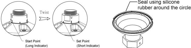
4.A silicone rubber sealant must be applied to seal the housing to secure waterproofing.
CAUTION 1: A silicone rubber sealant must be appliedto seal the housing to secure waterproofing.
CAUTION 2: When installing the camera in an environment colder than 14°F ( -10°C), reset the camera 30 ~ 60 minutes after the installation.
6

2.1.1 Mounting the camera
The wall mounting plate must be attached to a structural object such as concrete that lwil support the weight of the mount and dome camera.
1.Using the mounting template or the mounting accessory itself, mark and drill the necessary holes in the mounting surface.
2.Pull all cables through the mounting accessory. See 2.2 Cabling the camera for more information.
3.Attach the wall mounting bracket to the mounting surface using plastic anchors and M8x35 screws. For a ceiling mounting bracket installation, use the plastic anchors to secure it to the mounting surface.
4.Wind both of the pipe ends thread with Teflon tape about 20 times for sealing. Use a silicone rubber sealant to seal the area where the mounting bracket and the pipe meet.
5.Place a bead of silicone sealant around the mounting bracket’s mounting flange, press it to the surface and line up the flange hole with drilled holes.
6.Open the access plate on the mounting accessory and pull out the cables through the rectangular access hole.
7.Attach the 1.5” adapter to the mounting bracket and fix it using the set screw.
8.Attach the camera’s safety wire to the mounting bracket and organize the cables.
9.Connect all the cables to the camera. See 2.2 Cabling the camera. Close the access plate off the mounting bracket.
10.Connect the camera to the mounting bracket by turning it clockwise into the adapter, and fix it using the set screw of the adapter.
7
2.2 Cabling the camera
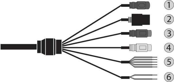
Follow the table and diagram below to connect your camera to all external devices.
No. |
|
|
Connector |
|
Wire Color |
|
Description |
|
|
|
|
|
|
|
|
1 |
|
|
Power jack |
|
Black |
|
Camera power |
|
|
|
|
(12vdc) |
|||
|
|
|
|
|
|
|
|
|
|
|
|
|
|
|
|
2 |
|
|
RJ-45 |
|
Black |
|
Ethernet |
|
|
|
|
|
|
|
|
3 |
|
|
RCA jack |
|
Black |
|
Audio input |
|
|
|
|
|
|
|
|
4 |
|
|
RCA jack |
|
Gray |
|
Audio output |
|
|
|
|
|
|
|
|
|
|
|
|
|
Yellow |
|
Alarm input 1 |
|
|
|
|
|
|
|
|
|
|
|
|
|
White |
|
Alarm input 2 |
|
|
|
|
|
|
|
|
5 |
|
|
5-pin cable |
|
Violet |
|
Alarm input 3 |
|
|
|
|
|
|
|
|
|
|
|
|
|
Brown |
|
Alarm input 4 |
|
|
|
|
|
|
|
|
|
|
|
|
|
Gray |
|
GND |
|
|
|
|
|
|
|
|
6 |
|
|
2-pin cable |
|
Red |
|
Alarm output |
|
|
|
|
|
|
||
|
|
|
Black |
|
GND |
||
|
|
|
|
|
|
||
|
|
|
|
|
|
|
|
The camera must be installed by qualified service personnelfollowing all local and federal electrical and building codes.
•Connecting to the RJ-45
Connect a standard RJ-45 cable to the network port of the camera. Generally, a crossover cable is used for direct connection to PC, while a direct cable is used for connection to a hub.
•Connecting alarms A1, A2, A3, A4 (alarm input 1, 2, 3, 4)
8
You can use external devices to signal the camera to reactto events. Mechanical or electrical switches can be wired to the A1, A2, A3, A4Alarm( Input 1, 2, 3, 4) and G (Ground) connectors.
NOTE: All the connectors marked G or GND is common.
Connect the ground side of the alarm input and/or alarm output to the G (Ground) connector.
•AO (alarm output)
The camera can activate external devices such as buzzers or lights. Connect the device to the AO (alarm output) and G (ground) connectors.
•Connecting audio
Connect the speaker to the audio output line and external mic to the audio input line.
•Connecting the power
o12VDC
Connect the power of12VDC for the camera. Connect the positive (+) pole to the ‘+’ position and the negative (-) pole to the ‘-’ position.
NOTE: Be careful not to reverse the polarity when you connect the power cable.
oPoE and 12VDC
Connect the power of 12VDC for the camera. Connect the positive (+) pole to the ‘+’ position and the negative (-) pole to the ‘-’ position.
NOTE: Be careful not to reverse the polarity when you connect the power cable. NOTE: If you use PoE to supply power to the camera, you must useaPoE injector or switch greater than 30W.
9

2.3Connections
SD card insertion
Users can insert and remove an SD card as shown in the following picture.
1.Open the SD card cover under the camera’s lens.
2.Insert or remove the SD card as needed.
3.Tightly close the SD card cover to ensure it is waterproof.
2.4 Resetting the camera to default settings
To reset the camera to its original factory settings, open the camera’s web viewer and go to the Setup > System > Maintenance. You can also use theReset button on the camera, as described below:
10
Using the reset button:
Follow the instructions below to reset the camera to the factory default settings using the Reset button.
1.Switch off the camera by disconnecting the power adapter.
2.Open the SD card cover.
3.Press and hold the reset button on the board with your finger while reconnecting the power.
4.Hold the reset button down for about 2 seconds.
5.Release the reset button.
6.The camera resets to factory defaults and restarts after completing the factory reset.
7.Close the SD card cover tightly to ensure waterproofing.
CAUTION: When performing afactory reset, you will lose all settings (Default IP 192.168.30.220)
11
3 Web viewer
The camera can be used withthe Windows® operating system and browsers. The recommended browsers are Internet Explorer, Safari, Firefox, Opera and Google Chrome with Windows.
NOTE: To view streaming video in Microsoft Internet Explorer, set your browser to allow ActiveX controls.
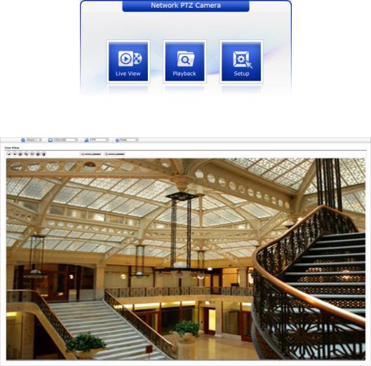
3.1 Access from a browser
1.Start a browser (Internet Explorer).
2.Enter the IP address or hostname of thecamera in the Location/Address field of your browser.
3.You can see a starting page. Click Live View, Playback, or Setup to enter the web page.
4. The cameras Live View page appears in your browser.
12
3.2 Access from the Internet
Once connected, the camera is accessible on your local network (LAN). To access the camera from the Internet you must configure your broadband router to allow incoming data traffic to the camera. To do this, enable the NAT traversal feature, which will attempt to automatically configure the router to allow access to thecamera. This is enabled from Setup > System > Network > NAT. For more information, please see “System > Network > NAT” of User Manual.
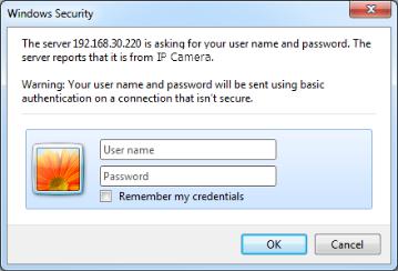
3.3 Setting the admin password over a secure connection
To gain access to the product, the password for the default administrator user must be set. This is done in the Admin Password dialog, which is displayed when thecamera is accessed for the setup for the first time. Enter your admin name and password, set by the administrator.
NOTE: The default administrator user name and password is“admin”. If the password is lost, the camera must be reset to the factory default settings. Please see “Resetting to the factory default settings”.
To prevent network eavesdropping when setting the admin password, this can be done via an encrypted HTTPS connection, which requires an HTTPS certificate (see NOTE below). To set the password via a standard HTTP connection, enter it directly in the first dialog shown above. To set the password via an encrypted HTTPS connection, please see“System > Security > HTTPS” of User Manual.
NOTE: HTTPS (Hypertext Transfer Protocol over SSL) is a protocol used to encrypt the traffic between web browsersand servers. The HTTPS certificate controls the encrypted exchange of information.
13
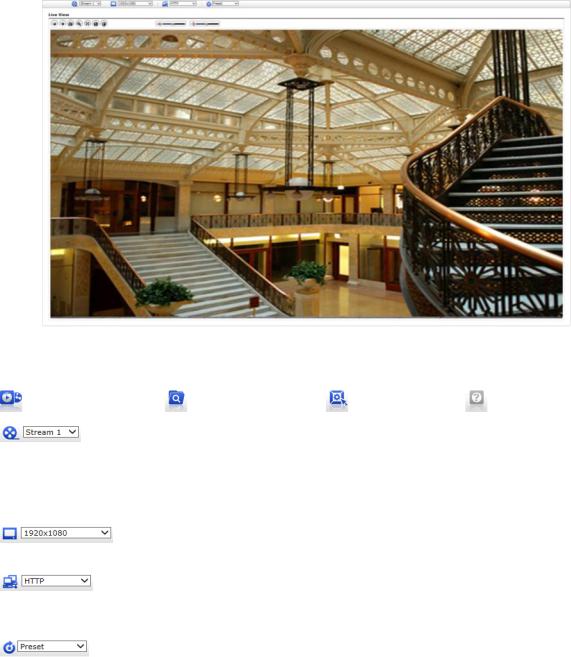
3.4 Live View Page
The Live View page comes in several screen modes. Users are allowed to select the most suitable one out of those modes. Adjust the modefollowing your PC specifications and monitoring purposes.
1. General controls |
|
|
|
|
|
Live View Page |
Playback Page |
Setup Page |
Help Page |
||
The video drop-down-list |
allows |
you |
to select |
a customized o |
|
preprogrammed video stream |
on the |
Live View |
page. Stream |
profiles are |
|
configured under Setup > Basic Configuration > Videoand Image. For more information, please see “Basic Configuration > Video and Image” of the User Manual.
The resolution drop-down-list allows you to select the most suitableone out of video resolutions to be displayed on the Live View page.
The protocol drop-down-list allows you to select which combination of protocols and methods to use depending on your viewing requirements, and the properties of your network.
The preset drop-down-list allows you to select the preset number for the PTZ camera being used. This icon is inactivated if the PTZ settings are not set.
14

2.Control toolbar
The live viewer toolbar is available in the web browser page only. It displays the follo wing buttons:
The Stop button stops the video stream being played. Pressing the key again toggles the play and stop.
The Play button connects to the camera or starts playing a video stream.
The Pause button pauses the video stream being played.
The Snapshot button takes a snapshot of the current image. The location where the image is saved can be specified.
The Digital Zoom button activates a zoom-in or zoom-out function for a video image on the live screen.
The Full-Screen button causes the video image to fill the entire screen area. No other windows will be visible. Press the ’Esc’ button on the computer keyboard to cancel the full-screen view.
The Manual Trigger button activates a pop-up window to manually start or stop the event.
The PTZ button activates a pop-up window for Pan, Tilt and Zoom control.
The Screen Move button moves to the desired position on the screen. Move the clicked point to the center of the screen. When dragging, it moves to the center of the
box and zooms in.
The Relay Output button manually triggers relay out. (Thicons appears only if “Enable alarm out” is selected in “Event > Event Out > Alarm Out”.)
The Speaker button activates/deactivates external speakers.
The Mic button activates/deactivates microphone input.
Use this scale to control the volume of the speakers and microphones.
3.Video Streams
The camera provides several images and video stream formats. Your requirements and the properties of your network will determine the type you use.
The Live View page in thecamera provides access to H.264, H.265 and Motion JPEG video streams, and to the list of available video streams. Other applications and clients can also access these video streams/images directly, without going via the Live wVie page.
15
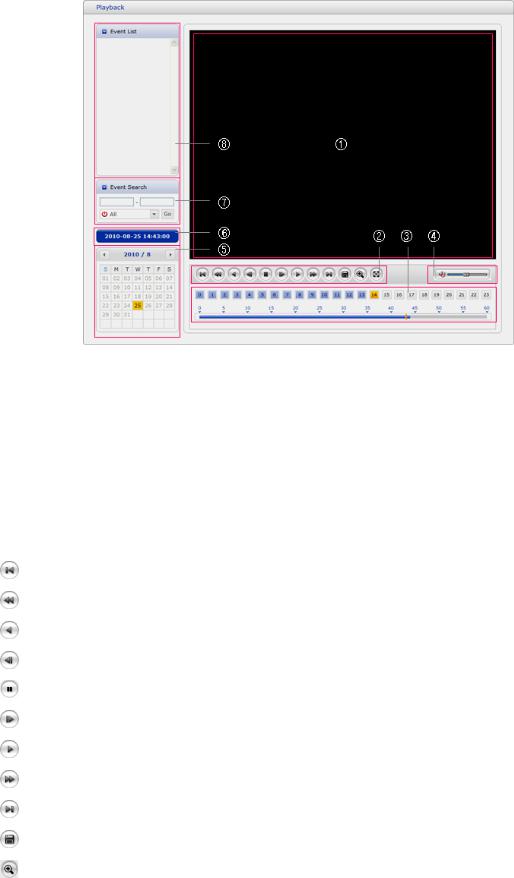
3.5 Playback
The Playback window contains a list of recordings made to the memory card. It shows each recording’s start time, length, the event type used to start the recording, calendar and timeslice bar indicates if the recording exists or not.
The description of the playback window follows.
1.Video Screen
You can see the video screen when playing the video clip in the SD memory.
2.Playback Buttons
To view a recording data in the SD local storage, select it from the list and click the Playback buttons.
Go to the first: go to the beginning of the video clip.
Fast backward play: fast play backward of the video clip.
Backward play: play backward of the video clip.
Step backward play: go back one frame of the video clip.
Pause: pause playback of the video clip.
Step forward play: go forward one frame of the video clip.
Forward Play: play forward the video clip.
Fast forward play: play fast forward of the video clip.
Go to the last: go to the end of the video clip.
Clip copy: copy the video clip.
Zoom In: zoom in the video clip.
 Full Screen: display a full screen of the video. 3. Time Chart
16
Display an hour-based search screen for the chosen date. If there is recording data, a blue section will be displayed on a 24-hour basis. If you select a specific hour in the chart, a yellow square on the hour will be displayed.
4.Speaker Control Bar
Use this scale to control the volume of the speakers.
5.Search Calendar
Search results from the SD local storage in the camera connected are displayed monthly. If there is a recorded data for a specific date, a blue square on the date will be displayed. If you select a specific date in the calendar, a yellow square on the date will be displayed.
6.Play Time
Displays the time of the video playing.
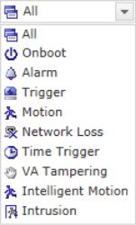
7.Event Search Window
Select a search option in the drop-down list and click the GO button. You can also enter the period for searching. If you click Start Date or End Date zone, displays Search Calendar.
8.Event List Window
Event List displays the event(s) that were recorded in the SD local storage. Select a list and click the play button. The video clip will be played.
17

3.6 Camera Setup
This section describes how to configure the camera.
The administrator has unrestricted acess to all the Setup tools, whereas Operators have access to the settings of Basic Configuration, which are Live View, Videoand Image, Audio, Event, Dome Configuration, and System.
You can configure the camera by clicking Setup either in the first connection page or the top second-right button of the Live View page. Accessing thecamera from a computer for the first time opens the Admin Password dialog box. Enter your administrator or operator id and password to get into the setup page.
NOTE: If the password is lost, the camera must be reset to the factory default settings. Please see “Resetting to the factory default setting”.
3.6.1 Basic Configuration
You can see the device information on this information page.
18
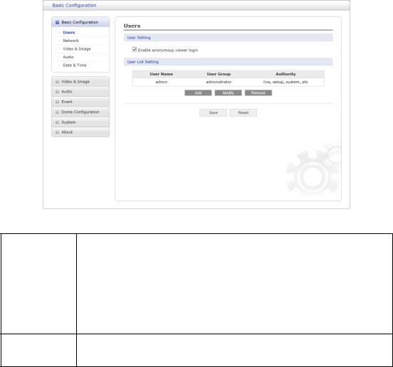
Users
User access control is enabled by default. The administrator can set up other users, by giving user names and passwords. It is also possible to allow anonymous viewer login, which means that anybody may access the Live View page, as described below:
The user list displays the authorized users and user groups (levels):
|
User Group |
|
|
Authority |
|
|
|
|
|
|
|
|
Guest |
|
|
The lowest level of access, which only allows access to the Live |
|
|
|
|
View page. |
|
|
|
|
|
|
|
|
|
|
|
|
|
|
|
|
|
|
View the Live View page, create and modify events, and adjust |
|
|
Operator |
|
|
certain other settings. Operatorshave no access to System |
|
|
|
|
|
Options. |
|
Administrato An administrator has unrestricted access to the Setup too
rand can determine the registration of all other users.
Enable anonymous viewer login:Check the box to use the webcasting features. Refer to “Video and Image > Webcasting” for more details.
Please refer to “System > Security > Users” for more details about User setup.
19
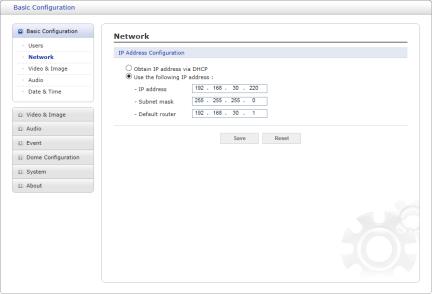
Network
The camera supports both IP version 4 and IP version 6. Both versions may be enabled simultaneously, and at least one ersionv must always be enabled. When using IPv4, the IP address for the camera can be set automatically via DHCP, or a static IP address can be set manually. If IPv6 is enabled, the camera receives an IP address according to the configuration
in the network router. There is also an option of using the Internet Dynamic DNS Service. For more information on setting the network, please see “System > Network > Basic”.
•Obtain IP address via DHCP: Dynamic Host Configuration Protocol (DHCP) is a protocol that lets network administrators centrally manage and automate the assignment of IP addresses on a network. DHCP is enabled by default. Although a DHCP server is mostly used to set an IP address dynamically, it is also possible to use it to set a static, known IP address for a specific MAC address.
oUse the following IP address: To use a static IP address for the camera, check the radio button and then make the following settings:
oIP address: Specify a unique IP address for your camera.
oSubnet mask: Specify the mask for the subnet the camera is located on.
•Default router: Specify the IP address of the default router (gateway) used for connecting devices attached to different networks and network segments.
NOTES:
1.DHCP should only be enabled if using dynamic IPaddress notification, or if your DHCP server can update a DNS server, which then allows you to access thecamera by name (hostname). If DHCP is enabled and you cannot access the unit, you may have to reset it to the factory default settings and then perform the installation again.
2.The ARP/Ping service is automatically disabled two minutes after the unit is started, or as soon as an IP address is set.
3.Pinging the unit is still possible when this service is disabled.
4.Please refer to “System > Network > Basic” for more details about the Network setup.
20
Video and Image
Users can setup and change the setting of an individual video stream on this page.
Please refer to “Video and Image > Basic” for more details about Video and Image setup.
21
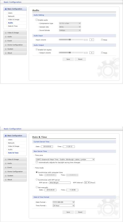
Audio
The camera can transmit audio to other clients using an external microphone and can play audio received from other clients by attaching a speaker. Usercan setup and changethe setting of Audio on this page.
Please refer to “Audio” for more details about the Audio setup.
Date and Time
Users can set time directly or assign a time server to get the current time, as well as determine Date and Time format on this page.
Please refer to “System > Date and Time” for more details about the Date and Time setup.
22
3.6.2 Video and Image
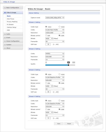
Basic
Sensor Setting:
•Capture mode: User can select sensor capture mode between NTSC and PAL (Some models are fixed to NTSC or PAL).
Stream 1 Setting:
•Codec: The codec supported in Stream 1 is H.264 and H.265.
There are 3 pre-programmed stream profiles available for quick set-up. Choose the form of video encoding you wish to use from the drop-down list:
oH.264 High Profile: Primary profile for broadcast and disc storage applications, particularly for high-definition television applications (for example, this is the profile adopted by the Blu-ray Disc storage format and the DVB HDTV broadcast service).
oH.264/H.265 Main Profile: Primary profile for low-cost applications that require
additional error robustness, this profile is used rarely in videoconferencing and
mobile applications; it does add additional error resilience tools to the Constrained Baseline Profile. The importance of this profile is fading after the Constrained Baseline Profile has been defined.
oH.264 Baseline Profile: Originally intended as the mainstream consumer profile for broadcast and storage applications, the importance of this profile faded
23
when the High Profile was developed for those applications.
•Resolution: This enables users to determine a basic screen size when having access through the Web Browser or PC program. The screen size control comes in several modes. Users can change the selected screen size anytime while monitoring the screen on a real-time basis.
•Bitrate control: The bit rate can be set as a Constrained Bit Rate (CBR) or Constrained Variable Bit Rate (CVBR). Limiting the maximum bit rate helps control the bandwidth used by the H.264 video stream. Leaving the Maximum bit rate as unlimited maintains consistently good image quality but increases bandwidth usage when there is more activity in the image. Limiting the bit rate to a defined value prevents excessive bandwidth usage, but images are degraded when the limit is exceeded.
oCBR: Constrained Bit Rate.
oCVBR: VBR with maximum bitrate which is set in Bitrate.
•Bitrate: Maximum bitrate in the range of 100Kbps ~ 10Mbps.
•Frame rate: Upon the real-time play, users should select a frame refresh rate per second. If the rate is high, the image will become smooth. On the other hand, if the rate is low, the image will not be natural, but it can reduce a network load.
•GOP size: Select the GOP (Group of Picture) size. If users want to have a high quality of fast image one by one, please decrease the value. For general monitoring, please do not change the basic value. Such an act may cause a problem to the system performance. For the details of the GOP setting, please contact the service center.
Stream 2 Setting:
Sometimes the image size is large due to low light or complex scenery. Adjusting the frame rate and quality helps to control the bandwidth and storage used by the Motion JPEG video
stream in these situations. Limiting the frame rate and quality optimizes bandwidth and storage usage but may give poor image quality. To prevent increased bandwidth and storage usage, the Resolution, Frame rate, and Frame Quality should be set to an optimal value.
•MJPEG Resolution: Same as the Stream 1 settings.
•MJPEG Frame rate: Same as the Stream 1 settings.
•MJPEG Quality: Select the picture quality. If users want to have a high quality of fast image one by one, please decrease the value. For general monitoring, please do not change the basic value. Such an act may cause a problem to the system performance.
Stream 3, Stream 4 Setting: Same as ‘Stream 1’ settings.
Click ‘Save’ to save the settings, or click ‘Reset’ to clear all the changes.
24
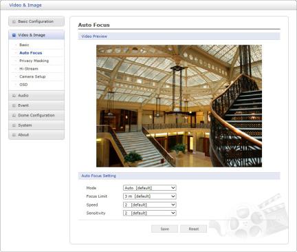
Auto Focus
•Mode: Determines the focus operation method.
oAuto: Autofocus is always active.
oManual: Manual focus is always a fixed focus.
oOne Push: Manual focus mode except that autofocus is activated only after the camera movement stops and lasts for about 5 seconds.
•Focus Limit: Minimum distance for Auto Focus operation. Object nearer than this limit may not be focused.
•Speed: Focus speed can be adjusted in the range of 1 ~ 7.
•Sensitivity: Focus sensitivity can be adjusted in the range of 0 ~ 4.
NOTES:
1.Avoid continuous, 24-hour use of the autofocus. This will shorten the lifespan of the lens.
2.The autofocus function might not work properly under the following conditions:
a.Bright or flashing lights.
b.Low illumination of the target area.
c.Slow-shutter action.
d.Dark object.
e.Excessive illumination of the target area.
f.If a short-distance object and a long-distance object are in the target area.
g.If there is no contract gap.
h.If the camera is taking a picture of a thin horizontal line.
Click ‘Save’ to save the settings, or click ‘Reset’ to clear all the changes.
25
 Loading...