


Desa Tech M125AT, M170AT, M200AT, PKHD125T, PKHD170T Owner's Manual
...PORTABLE FORCED AIR HEATERS
OWNER’S MANUAL
HEATER SIZES:
125,000, 170,000 AND 200,000 BTU/HR
KEROSENE/DIESEL HEATER WITH BUILT-IN THERMOSTAT
IMPORTANT: Read and understand this manual before assembling, starting or servicing heater. Improper use of heater can cause serious injury. Keep this manual for future reference.
TABLE OF CONTENTS
Safety Information ............................................... |
2 |
Preventative Maintenance Schedule................... |
8 |
Unpacking ........................................................... |
3 |
Troubleshooting................................................... |
8 |
Fuels.................................................................... |
3 |
Service Procedures........................................... |
10 |
Product Identification........................................... |
3 |
Specifications .................................................... |
15 |
Theory of Operation ............................................ |
4 |
Wiring Diagrams................................................ |
16 |
Ventilation............................................................ |
4 |
Technical Service .............................................. |
17 |
Assembly............................................................. |
4 |
Replacement Parts............................................ |
17 |
Operation............................................................. |
5 |
Accessories....................................................... |
17 |
Operation with Portable Generator...................... |
7 |
Illustrated Parts Breakdown and Parts List ....... |
18 |
Storing, Transporting or Shipping........................ |
7 |
Warranty and Repair Service ............................ |
28 |
Fill In For Your Records
Model No. __________________
(Located on side panel)
Serial No. __________________
(Located on fuel tank)
Date of Purchase: ____________
Save this manual for future reference. For more information, visit www.desatech.com

SAFETY INFORMATION
 WARNING:Thisproductcontainsand/orgenerateschemicals known to the State of California to cause cancer or birth defects or other reproductive harm.
IMPORTANT: Read this owner’s manual carefully and completely beforetryingtoassemble,operate or service this heater. Improper use of this heater can cause seriousinjuryordeathfromburns,fire, explosion, electrical shock and carbon monoxide poisoning.
 DANGER: Carbon monoxide poisoning may lead to death!
Carbon Monoxide Poisoning: Early signs of carbon monoxide poisoning resemble the flu, with headaches, dizziness and/or nausea. If you have these signs, the heater may not be working properly. Get fresh air at once! Have heater serviced. Some people are more affected by carbon monoxide than others. These include pregnant women, persons with heart or lung disease or anemia, those under the influence of alcohol and those at high altitudes.
Make certain you read and understand all warnings. Keep this manual for reference. It is your guide to safe and proper operation of this heater.
1.Useonlykerosene,#1/#2diesel/fueloil,JETA or JP-8 fuels to avoid risk of fire or explosion. Never use gasoline, naphtha, paint thinners, alcohol or other highly flammable fuels.
2.Fueling
a)Personnel involved with fueling shall be qualified and thoroughly familiar with the manufacturer's instructions and applicable regulations regarding the safe fueling of heating units.
b)Only the type of fuel specified on the heater's data plate shall be used.
c)All flame, including the pilot light, if any, shall be extinguished and the heater allowed to cool, prior to fueling.
d)During fueling, all fuel lines and fuel-line connections shall be inspected for leaks. Any leaks shall be repaired prior to returning the heater to service.
e)At no time shall more than one day's supply of heater fuel be stored inside a building in the vicinity of the heater. Bulk fuel storage shall be outside the structure.
f)All fuel storage shall be located a minimum of 762 cm (25 feet) from heaters, torches, welding equipment and similar sources of ignition (exception: the fuel reservoir integral with the heater unit).
g)Whenever possible, fuel storage shall be confined to areas where floor penetrations donotpermitfueltodripontoorbeignited by a fire at lower elevation.
h)Fuel storage shall be in accordance with the authority having jurisdiction.
3.Use only the electrical voltage and frequency specified on model plate.
4.Heater must be grounded. Use only a properly grounded three-wire extension cord. Plug into grounded outlet only.
5.Use only in areas free of flammable vapors or high dust content.
6.Minimum clearance from any combustible materials: 8 feet (244 cm) from hot air outlet; 6 feet (183 cm) from top; and 4 feet (120 cm) from sides and inlet.
7.Locate heater on a stable and level surface while hot or operating or a fire may occur.
8.Use only in well-vented areas. Before using heater,provideatleasta2800squarecm(three- square-foot) opening of fresh, outside air for each 30 kw (100,000 Btu/Hr) of rating.
9.Keep children and animals away from heater at all times.
10.Never start heater when combustion chamber ishotoriffuelhasaccumulatedincombustion chamber.
11.When used with thermostat, heater may start at anytime.
12.When heater is moved or stored, it must be in a level position or fuel spillage may occur.
13.Use heater only in accordance with local ordinances and codes.
14.Never use gasoline, crankcase drainings, naphtha,paintthinners,alcoholorotherhighly flammable fuels.
15.Never use heater where gasoline, paint thinner or other highly flammable vapors are present.
16.Never use heater in living or sleeping areas.
17.Never leave a heater plugged in without adult supervision if children or animals are likely to be present.
2 |
www.desatech.com |
113170-01E |
SAFETY INFORMATION
Continued
18.Never move, handle, refuel or service a hot, operating or plugged-in heater.
19.Never attach duct work to front or rear of heater.
20.Never attach heater to external fuel tank.
21.Heaters used in the vicinity of tarpaulins, canvas or similar enclosure materials shall be located a safe distance from such materials. The recommended minimum safe distance is 304.8 cm (10 feet). It is further recommended that these enclosure materials be of a fire retardant nature. These enclosure materials shall be securely fastened to prevent them from igniting or from upsetting the heater due to wind action.
22.Unplug heater when not in use.
23.Never block air inlet (rear) or air outlet (front) of heater.
24.Warning to New York City Residents
For Use Only At Construction Sites in accordance with applicable NYC codes under NYCFD certificate of approval #4803, #4899, #4908, #4909 or #4934.
UNPACKING
1.Remove all packing items applied to heater for shipment.
2.Remove all items from carton.
3.Check items for any shipping damage. If heater is damaged, promptly inform dealer where you bought heater.
FUELS
 WARNING: Use only kerosene, #1/#2 diesel/fuel oil, JET
A or JP-8 fuels to avoid risk of fire or explosion. Never use gasoline, oil drained from crankcases, naphtha, paint thinners,alcoholorotherhighly flammable fuels.
Use only kerosene, #1/#2 diesel/fuel oil, JET A or JP-8 fuels. Heavier fuels such as No. 2 fuel oil or No. 2 diesel fuel may also be used but will result in:
•noticeable odor
•additional fuel filter maintenance
•theneedfor nontoxic,anti-iceradditivesin very cold weather
Do not use fuels heavier than No. 2 grade or heavy oils such as oil drained from crankcases. These heavy oils will not ignite properly and will contaminate the heater.
IMPORTANT: Use a KEROSENE ONLY (blue) or DIESEL ONLY (yellow) storage container. Be sure storage container is clean. Foreign matter such as rust, dirt or water will cause the ignition control assembly to shut down heater. Foreign matter may also require heater's fuel system to be frequently cleaned.
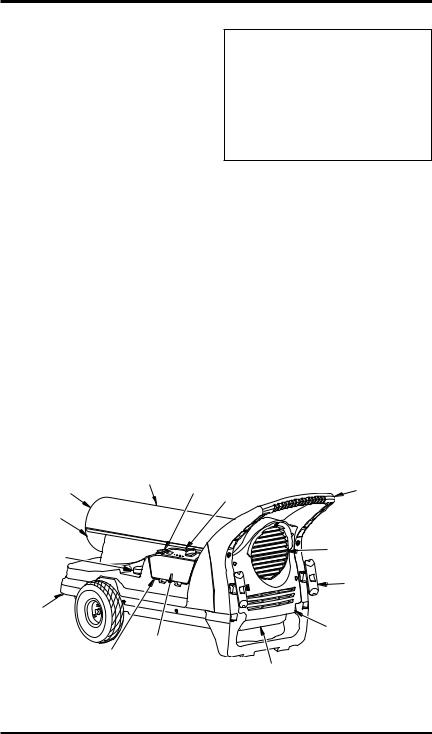
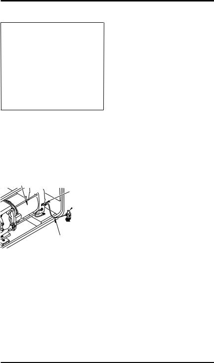
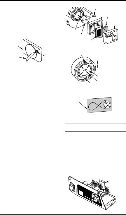
PRODUCT IDENTIFICATION
Hot Air |
Upper Shell |
ON/OFF |
|
Switch |
|||
Outlet |
|
||
|
|
||
Lower |
|
|
|
Shell |
|
|
|
Fuel Cap/ |
|
|
|
Gauge |
|
|
Thermostat |
Handle |
Knob |
|
|
Fan |
|
Guard |
|
Extension |
|
Cord Wrap |
Shroud
Ignition Control |
|
|
Control Cover Assembly (On |
|
|
Inside of Control |
Fuel Tank |
|
Cover) |
||
|
Rear Panel
Figure 1 - 125T, 170T and 200T Models
113170-01E |
www.desatech.com |
3 |
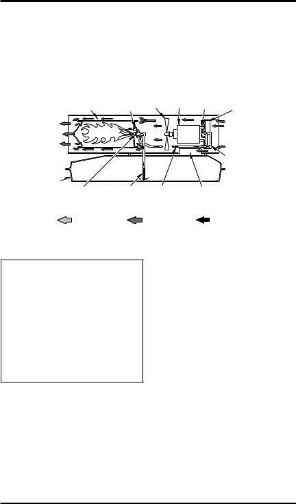
THEORY OF OPERATION
The Fuel System: The air pump forces air through the air line. The air is then pushed through the nozzle. This air causes fuel to be lifted from the tank. A fine mist of fuel is sprayed into the combustion chamber.
The Air System: The motor turns the fan. The fan pushes air into and around the combustion chamber. This air is heated and provides a stream of clean, hot air.
The Ignition System: The ignition control assembly provides power to the ignitor. This ignites the fuel/air mixture in the combustion chamber.
The Flame-Out Control System: This system causes the heater to shut down if the flame goes out.
Combustion Chamber |
Ignitor |
Fan Motor |
Air Pump Air Intake Filter |
Clean |
|
|
Cool Air In |
Heated |
|
|
|
Air Out |
|
|
|
|
|
|
Air Output Filter |
Fuel |
|
|
|
Tank Nozzle |
Fuel |
Air Line |
Ignition Control |
|
Filter |
To Burner |
Assembly |
Air For Fuel |
|
Air For |
|
|
Combustion |
Fuel |
|
System |
|
||
|
And Heating |
|
|
|
|
|
Figure 2 - Cross Section Operational View
VENTILATION
 WARNING:Provideafreshair opening of at least three square feet (2,800 square cm) for each
100,000 BTU/HR rating. Provide extra fresh air if more heaters are being used. The minimum ventilation requirements must be followedtoavoidrisksassociated withcarbonmonoxidepoisoning.
Make certain these requirements are met prior to operating heater.
Example: A 58.6 kw (200,000 Btu/Hr) heater requires one of the following:
•a two-car garage door [4.88 meter (16 feet) opening] raised 12.7 cm (5 inches)
•a single-car garage door [2.74 meter (9 feet) opening] raised 20.3 cm (8 inches)
•two, 76.2 cm (30 inch) windows raised 38.1 cm (15 inches)
ASSEMBLY
These models are furnished with wheels and a rear handle.Wheels,handleandthemountinghardware are found in the shipping carton.
Tools Needed
•Medium Phillips Screwdriver
•Rubber Mallet/Hammer
•Flat Blade Screwdriver
1.Slide axle through holes in shroud. Install washers, wheel spacers and wheels on axle as shown in Figure 3, page 5.
IMPORTANT: When installing wheels, point extended hub of wheels toward shroud (see Figure 3, page 5).
2.Place cap nuts on axle ends. Gently tap with hammer to secure.
3.Install extension cord wraps into handle.
4.Slide handle onto shroud leaving a one inch gap between parts.
5.Place washers onto screws and insert screws into holes in handles.
6.Visually confirm that all six screws are threaded into the shroud. Push the handle completely into the shroud.
7.Tighten all screws.
4 |
www.desatech.com |
113170-01E |
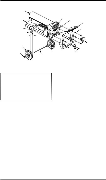
ASSEMBLY
Hot Air Outlet
Shroud
Shroud
Axle Hole
Wheel 

Spacer
Washer
Wheel
Continued
Air Inlet
Rear Panel
Handle
Washer
Extension
 Cord Wrap
Cap Nut |
Extended Hub |
|
|
|
Axle |
Screw
Figure 3 - Wheel and Handle Assembly
OPERATION
IMPORTANT:ReviewandunderstandthewarningsintheSafety Information section, page 2. They are needed to safely operate this heater. Follow all local ordinances and codes when using this heater.
TO START HEATER
1.Follow all ventilation and safety information.
2.Locateheatertoprovidemaximumcirculation of the heated air. Follow all location requirements noted in Safety Information, page 2.
3.Fill fuel tank with fuel. Use only kerosene, #1/#2 diesel/fuel oil, JET A or JP-8 fuels to avoid risk of fire or explosion. Never use gasoline, naphtha, paint thinners, alcohol or other flammable fuels.
4.Attach fuel cap/gauge.
5.Plug heaterʼs power cord into approved, grounded,three-wireextensioncord.Extension cord must be at least six feet (1.8 meters) long.
Extension Cord Size Requirement
6to10feet(1.8to3meters)long,use18AWG (0.75 mm2) rated cord
11 to 100 feet (3.3 to 30.5 meters) long, use 16 AWG (1.0 mm2) rated cord
101 to 200 feet (30.8 to 61 meters) long, use 14 AWG (1.5 mm2) rated cord
6.Plug extension cord into standard 120 volt/60 hertz, 3-prong grounded outlet.
7.Turn thermostat knob to the right (clockwise) to the warmest position.
8.Push ON/OFF switch to the ON (|) position. Light will come on. Note:Ignitor will preheat for five seconds, then heater will start.
9.Afterheaterisrunning,adjustthermostatknob tothedesiredsetting.Note:Acoldheatermay affectthethermostatsetting.Thisthermostatis a general-heating control. It is not intended for precisetemperaturecontrol.Adjustthermostat until heater cycles at the desired setting.
TO STOP HEATER
1.Push ON/OFF switch to the OFF (O) position.
2.Unplug heater.
TO RESET HEATER
1.Push ON/OFF switch to the OFF (O) position and wait 10 seconds. (Wait two minutes if heater has been running.)
2.Repeat steps under To Start Heater.
113170-01E |
www.desatech.com |
5 |
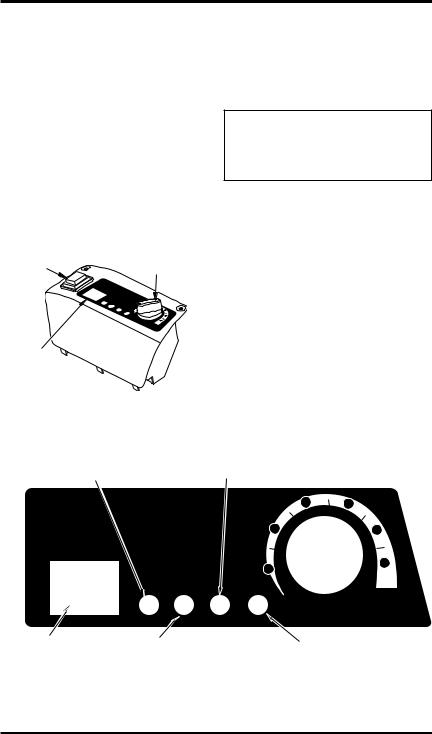
OPERATION
Continued
RL, RE AND PKHD SERIES MODELS |
|||
ONLY |
|
|
|
Temperature Display |
|
||
These models are equipped with a digital tem- |
|||
perature display. The temperature being shown |
|||
represents the air nearest to the control cover. The |
|||
temperature of the air in surrounding areas may |
|||
be much different from the temperature being |
|||
displayed. The display may show [ - - ] when the |
|||
thermostat control or temperature sensor are dis- |
|||
connected from the ignition control or if they are |
|||
or damaged. If this occurs, the safety control will |
|||
continue to operate as before, however, the unit |
|||
will not cycle off during operation. See Figure 4. |
|||
Lighted |
ON/OFF |
Thermostat |
|
Switch |
|
||
|
Control |
||
|
|
||
|
T |
|
|
|
Temempe |
ra |
|
|
p |
|
|
|
eraturature |
|
|
|
|
2 |
3 |
|
|
1 |
4 |
|
|
LO |
5 |
|
|
Te |
6 |
|
|
ostatoat |
|
|
|
|
HI |
Temperature |
|
|
|
Display |
|
|
|
Figure 4 - Control Cover with |
|||
|
Temperature Display |
||
LED Indicator Lights ThesemodelsareequippedwithLEDlightsinorder to help monitor your heater and to help diagnose anypotentialproblemsassociatedwithyourheater. Make sure you have read all of the instructions and see Troubleshooting, page 8, before attempting to rectify any problems with your heater.
 WARNING: Never service heater while it is plugged in, operating or hot. Severe burns and electrical shock can occur.
LOGIC ENHANCED IGNITION These models have an electronically controlled ignition system that is able to detect problems during startup and is able to apply an automatic “choke” to increase the likelihood of ignition. If the heater does not ignite within the first second the motor will slow down momentarily. If your heater does not light after the first “choke” it will repeat once. If the heater does not ignite after the second “choke” it will shutdown and remain in shutdown mode until the unit is reset. Please refer to Troubleshooting, page 8 in order to properly diagnose the problem.
Ignitor - indicates a problem with the ignitor and can be caused by a damaged or broken ignitor or an ignitor that is wired incorrectly.
Flame - will illuminate after heater is shut down due to problems associated with the flame or the photocell that monitors the flame.
Temperature
Temperatura
Vo |
|
|
|
|
|
|
|
l |
|
|
|
|
|
|
|
tage |
Flame |
|
|
|
|||
|
• |
|
|
|
|
|
|
Ignitor |
|
|
|
• |
Encend |
|
|
Te |
|
|
|
|
|
||
|
|
|
|
|
DémaStar |
|
|
• |
nsión |
Llama |
|
i |
|
||
|
|
|
|
|
|||
|
|
|
|
|
|
do/ |
|
|
|
• |
|
• |
rre/ t/Run |
||
Allumeu |
|
|
|
|
|
||
Encended |
Te |
|
|
|
Ma |
|
|
|
|
|
|
Operac |
|||
r |
|
|
|
Flamme |
r |
|
|
|
nsio |
|
|
||||
|
|
|
|
|
|
che |
i |
|
|
|
|
|
|
|
|
or |
|
n |
|
|
ón |
||
34
25
1 |
6 |
|
|
LO |
HI |
Thermostat |
|
|
Termostato |
112935-01
Temperature
Display
Voltage - monitors line voltage during normal operation and indicates improper line voltage. If line voltage falls below 108V or above 132V the heater will shut down.
Start/Run - blinks during “preheat” for 10-15 seconds before ignition and will stay on during normal operation.
Figure 5 - LED Indicator Lights
6 |
www.desatech.com |
113170-01E |
OPERATION WITH PORTABLE GENERATOR
 WARNING: Before operating heater or any appliance from a portable generator, verify that generatorhasbeenproperlyconnectedtoearthground.Improper grounding or failure to ground generator can result in electrocution if a ground fault occurs. Refertoowner’smanualsupplied by generator manufacturer for proper grounding procedures.
The operating voltage range of the heater is 108 to 132 Volts (120 Volts +/- 10%). Prior to plugging heater into generator the output voltage should be verified(ifgeneratorisequippedwiththeautomatic idle feature, the output voltage should be measured withthegeneratorrunningatfullspeed).Ifthevoltagedoesnotmeasureinthisrangetheheatershould not be plugged into the generator.
Refer to Operation, page 5, for starting, stopping and resetting heater procedures.
Alternator 

 Ground Lug
Copper
 or Brass
Grounding
Point
Ground Wire (#10 AWG
- Stranded-Copper)
Figure 6 - Typical Generator Grounding Method (Generator construction may vary from that shown)
STORING, TRANSPORTING OR SHIPPING
Note: If shipping, transport companies require fuel tanks to be empty.
1.Remove drain plug from bottom side of fuel tank and drain all fuel.
2.Replace drain plug.
3.If any debris is noted in old fuel, add 1 or 2 quarts of clean kerosene to tank, stir and drain again. This will prevent excess debris from clogging filters during future use.
4.Properly dispose of old and dirty fuel. Check with local automotive service stations that recycle oil.
5.If storing, store heater in dry place. Make sure storage place is free of dust and corrosive fumes.
IMPORTANT: Do not store kerosene over summer months for use during next heating season. Using old fuel could damage heater.
113170-01E |
www.desatech.com |
7 |

PREVENTATIVE MAINTENANCE SCHEDULE
 WARNING: Never service heater while it is plugged in, operating or hot. Severe burns and electrical shock can occur.
Item |
How Often |
How To |
|
|
|
Fuel tank |
Flushevery150-200hoursofoperation |
See Storing, Transporting, or |
|
or as needed |
Shipping, page 7 |
Air output and lint filters |
Replace every 500 hours of operation |
See Air Output, Air Intake and |
|
or once a year |
Lint Filters, page 10 |
Air intake filter |
Washanddrywithsoapandwaterevery |
See Air Output, Air Intake and |
|
500 hours of operation or as needed |
Lint Filters, page 10 |
Fuel filter |
Clean twice a heating season or as |
See Fuel Filter, page 11 |
|
needed |
|
Ignitor |
No maintenance required |
|
Fan blades |
Clean every season or as needed |
See Fan, page 10 |
Motor |
Not required/permanently |
|
|
lubricated |
|
TROUBLESHOOTING
 WARNING: Never service heater while it is plugged in, operating or hot. Severe burns and electrical shock can occur.
FAULT CONDITION |
POSSIBLE CAUSE |
REMEDY |
||
|
|
|
|
|
Motor does not start five seconds |
|
|
|
|
after heater is plugged in |
|
|
|
|
INDICATOR LIGHT |
1. |
No power to heater |
1. |
Check circuit breaker in elec- |
• Ignitor |
2. |
ON/OFF switch not in the ON |
|
trical panel |
|
2. |
VerifytheON/OFFswitchisin |
||
|
|
(|) position |
|
ON (|) position and light is on |
|
3. |
Thermostat setting is too low |
3. |
Turn thermostat knob to a |
|
|
|
|
higher setting |

 WARNING: High voltage!
4. |
Bad electrical connection be- |
4. |
Check all electrical connec- |
|
tween motor and ignition con- |
|
tions. See Wiring Diagrams, |
|
trolassemblyorignitioncontrol |
|
page 16 |
|
assembly and power cord |
5. |
If fan does not turn freely, see |
5. |
Binding pump rotor |
||
6. |
Blown fuseon ignition control |
|
Pump Rotor, page 14 |
6. |
SeeIgnitionControlAssembly, |
||
|
assembly |
|
page 14 |
7. |
Defective ignition control |
7. |
Replace ignition control |
|
assembly |
|
assembly |
8. |
Defective motor |
8. |
Replace motor |
8 |
www.desatech.com |
113170-01E |

TROUBLESHOOTING
Continued
FAULT CONDITION |
POSSIBLE CAUSE |
REMEDY |
||
|
|
|
|
|
Motor starts and runs but heater |
|
|
|
|
does not ignite |
|
|
|
|
INDICATOR LIGHT |
1. |
No fuel in tank |
1. |
Fill tank with kerosene |
• Flame |
2. |
Pump pressure incorrect |
2. |
See Pump Pressure Adjust- |
|
3. |
Dirty fuel filter |
|
ment, page 10 |
|
3. |
See Fuel Filter, page 11 |
||
|
4. |
Obstruction in nozzle |
4. |
See Nozzle Assembly, page 12 |
|
5. |
Water in fuel tank |
5. |
Drain and flush fuel tank with |
|
|
|
|
clean kerosene. See Storing, |
|
|
|
|
Transporting or Shipping, |
|
|
|
|
page 7 |
|
|
|
|
|
WARNING: High voltage! |
|
|
||
|
|
|
|
|
|
|
|
|
|
• |
Ignitor |
6. Bad electrical connection |
6. |
Check electrical connections. |
|||||
|
|
|
between ignitor and ignition |
|
See Wiring Diagrams, page 16 |
||||
|
|
|
control assembly |
7. |
Replace ignitor, see page 11 |
||||
|
|
7. |
Defective ignitor |
||||||
|
|
8. |
Defective ignition control |
8. |
Replace ignition control |
||||
|
|
|
assembly |
|
assembly |
||||
• |
Voltage |
9. Line voltage is below 108V or |
9. |
Check for proper line voltage |
|||||
|
|
|
above 132v |
|
|
|
|
||
|
|
|
|
|
|
|
|
|
|
Heaterignitesbutignitioncontrol |
|
|
|
|
|
|
|
|
|
assembly shuts heater off after a |
|
|
|
|
|
|
|
|
|
short period of time |
|
|
|
|
1. |
See Pump Pressure Adjust- |
|||
INDICATOR LIGHT |
1. Pump pressure incorrect |
||||||||
• Flame |
2. |
Dirty air intake, air output |
|
ment, page 10 |
|||||
|
|
2. |
See Air Output,Air Intake and |
||||||
|
|
|
and/or lint filter |
|
Lint Filters, page 10 |
||||
|
|
3. |
Dirty fuel filter |
3. |
See Fuel Filter, page 11 |
||||
|
|
4. |
Obstruction in nozzle |
4. |
See Nozzle Assembly, page 12 |
||||
|
|
5. |
Photocellassemblynotproperly |
5. |
Make sure photocell boot is |
||||
|
|
|
installed (not seeing the flame) |
|
properly seated in bracket |
||||
|
|
6. |
Dirty photocell lens |
6. |
Clean photocell lens |
||||
|
|
|
|
|
|
|
|||
|
|
|
|
|
WARNING: High voltage! |
|
|||
|
|
|
|
|
|
|
|||
• |
Voltage |
7. Bad electrical connection be- |
7. |
Check electrical connections. |
|||||
|
|
|
tween photocell and ignition |
|
See Wiring Diagrams, page 16 |
||||
|
|
|
control assembly |
8. |
Replace photocell |
||||
|
|
8. |
Defective photocell |
||||||
|
|
9. |
Defective ignition control |
9. |
Replace ignition control |
||||
|
|
|
assembly |
|
assembly |
||||
|
|
10.Line voltage is below 108Vor |
10.Check for proper line voltage. |
||||||
|
|
|
above 132v |
|
Disconnect power equipment |
||||
|
|
|
|
|
|
|
that may be used on same |
||
|
|
|
|
|
|
|
line |
||
113170-01E |
www.desatech.com |
9 |
SERVICE PROCEDURES
 WARNING: To avoid risk of burnandelectricalshock,never attempttoserviceheaterwhileit is plugged in, operating or hot.
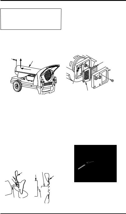
UPPER SHELL REMOVAL
1.Removescrewsalongeachsideofheaterusing phillipsscrewdriver.Thesescrewsattachupper and lower shells together. See Figure 7.
2.Lift upper shell off.
3.Remove fan guard.
Screw |
Upper Shell |
|
|
|
2 |
|
1 |
Figure 7 - Upper Shell Removal
FAN
IMPORTANT: Remove fan from motor shaft before removing motor from heater. The weight of the motor resting on the fan could damage the fan pitch (see Figure 8).
1.Remove upper shell (see Figure 7).
2.Use 1/8" allen wrench to loosen setscrew which holds fan to motor shaft.
3.Slip fan off motor shaft.
4.Clean fan using a soft cloth moistened with kerosene or solvent.
5.Dry fan thoroughly.
6.Replacefanonmotorshaft.Placefanhubflush with end of motor shaft (see Figure 9).
7.Placesetscrewonflatofshaft.Tightensetscrew firmly (40-50 inch-pounds/4.5-5.6 n-m).
8.Replace upper shell.
Fan |
Setscrew |
|
|
Motor |
Fan |
||
|
|||
|
|
Setscrew
Motor Shaft
Figure 8 - Fan, Motor
Shaft and Setscrew
Location


 Flush
Flush
Motor
Shaft
Figure 9 - Fan
Cross Section
AIR OUTPUT, AIR INTAKE AND LINT FILTERS
1.Remove upper shell (see Figure 7).
2.Remove filter end cover screws using 5/16" nut-driver (see Figure 10).
3.Remove filter end cover.
4.Replace air output and lint filters.
5.Wash orreplace air intake filter (see Preventative Maintenance Schedule, page 8).
6.Replace filter end cover.
7.Replace upper shell.
IMPORTANT: Do not oil filters.
Air Intake
Filter
Filter
 End
End
Cover
Lint Filter
Air Output Filter
Figure 10 - Air Output, Air Intake and Lint
Filters
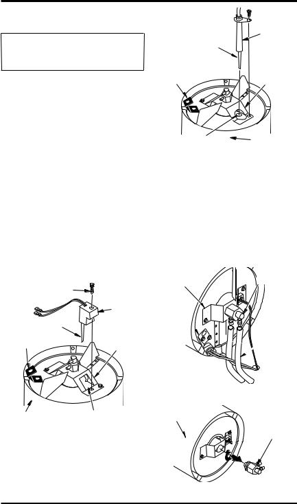
PUMP PRESSURE ADJUSTMENT
1.Remove fan guard using medium phillips screwdriver.
2.Remove pressure gauge plug from filter end cover (see Figure 11).
3.Install accessory pressure gauge (part number HA1180).
4.Start heater (see Operation, page 5). Allow motor to reach full speed.
Relief


 Valve
Valve
Pressure
Gauge
Plug
Figure 11 - Pressure Gauge Plug
Removal
10 |
www.desatech.com |
113170-01E |
SERVICE PROCEDURES
Continued
5.Adjust pressure. Turn relief valve to right to increase pressure. Turn relief valve to left to decrease pressure. See specifications below for correct pressure (see Figure 12).
6.Remove pressure gauge. Replace pressure gauge plug in filter end cover.
|
Pump |
Pressure |
|
|
Gauge |
||
Model |
Pressure |
||
|
|||
125T |
6.0 PSI |
|
|
170T |
6.0 PSI |
|
|
200T |
6.2 PSI |
|
Figure 12 - Adjusting Pump Pressure
FUEL FILTER
1.Unplug heater.
2.Remove control cover screws using medium phillips screwdriver.
3.Remove control cover.
4.Pull upper fuel line off fuel filter neck (see Figure 13).
5.Carefully pry bushing, fuel filter and lower fuel line out of fuel tank (see Figure 13).
6.Wash fuel filter with clean fuel and replace in tank.
7.Attach upper fuel line to fuel filter neck.
8.Replace control cover.
Screw
Control Cover
Fuel Filter, |
Bushing and |
Lower Fuel Line |
Upper Fuel Line
Figure 13 - Fuel Filter Removal
 WARNING: HIGH VOLTAGE
WARNING:Toavoidriskofburn and electrical shock, never attempttoserviceheaterwhileitis plugged in, operating or hot.
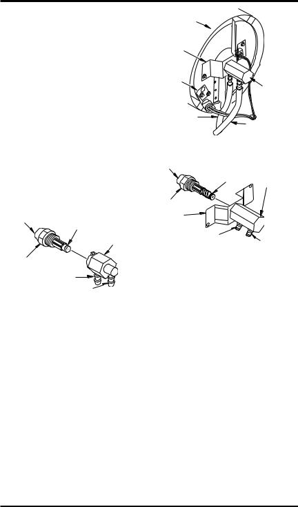
IGNITOR
1.Remove upper shell (See Upper Shell Removal, page 10).
2.Remove fan (see page 10).
3.Remove 2 control cover screws with a phillips screwdriver. Remove control cover (see Figure 13).
4.Disconnect ignitor wires from ignition control assembly (see Figure 14). Pull the ignitor wires up through the hole in the lower shell.
5.Disconnect fuel line hose and air line hose. Remove photocellfrom photocellbracket (see Figure 14).
6.Remove combustion chamber. Stand combustion chamber on end with nozzle adapter bracket on top (see Figure 15, page 12).
7.Remove ignitor screw with a 1/4" nut driver for models using ignitor HA1000 or 5/16" nut driver for models using ignitor HA1100. Carefully remove ignitor from nozzle adapter bracket.
8.Carefully remove replacement ignitor from styrofoam packing.
Combustion |
|
|
|
|
|
|
|
|
Nozzle Adapter |
|
|
|
|
|
|
|
|
Bracket |
|
Chamber |
|
|
|
|
|
|
|
|
|
Air Line Hose |
|
|
|
|
|
|
|
|
Ignitor |
|
|
|
|
|
|
|
|
|
Ignitor |
Photocell |
|
|
|
|
|
|
|
|
Wire |
Bracket |
|
|
|
|
|
|
|
|
|
Fuel Line |
|
|
|
|
|
|
|
|
|
Hose |
|
|
|
|
|
|
|
|
|
Photocell |
|
|
|
|
|
|
|
|
|
Assembly |
|
|
|
|
|
|
|
|
Ignitor |
|
|
|
|
|
|
|
|
|
|
|
|
|
|
|
|
|
|
|
Wire |
T |
V |
|
|
|
|
|
|
|
|
Temperat |
ol |
|
|
|
|
|
|
|
|
emperaure |
Ig |
|
|
|
|
|
|
|
|
tura |
nitortage• |
Flame |
|
|
|
|
|
|
|
|
All• |
Ten |
|
|
|
|
|
|
|
|
umEnc |
si |
• |
|
|
|
3 |
|
|
|
euen |
ón |
Lla En |
|
1 |
|
Ignition |
||
|
|
|
|
mF Dcie |
5 |
|
|||
|
rde |
•T |
2 |
4 |
|
|
|||
|
d |
en |
a• émarnS |
|
|
||||
|
|
or |
s |
la |
rda/tart |
|
|
|
|
|
|
|
io |
e/O |
|
|
|
|
|
|
|
|
n |
mme |
Mp |
|
|
|
|
|
|
|
|
arc |
|
|
|
|
|
Control Cover |
|
|
|
|
|
|
stato |
HI |
Control |
|
|
|
|
|
|
|
|
6 |
|
|
|
|
|
|
|
|
|
|
Assembly |
Figure 14 - Disconnecting Ignitor Wires |
|||||||||
from Ignition Control Assembly |
|||||||||
(170T Model Shown) |
|||||||||
113170-01E |
www.desatech.com |
11 |
SERVICE PROCEDURES
Continued
 CAUTION: Do not bend or strike ignitor element. Handle with care.
9.Carefully guide ignitor into opening in nozzle adapter bracket. Do not strike ignitor element. Attach ignitor to nozzle adapter bracket with screw using a 1/4" nut driver for models using ignitor HA1000 (see Figure 15) or 5/16" nut driver for models using HA1100 ignitor (see Figure 16). Torque .90 to 1.69 N-m (8 to 15 in-lbs) Do not over torque.
10.Replace combustion chamber.
11.Route the ignitor wires back down through the hole in the lower shell. Connect wires to the ignition control assembly (see Figure 14, page 11).
12.Replace control cover (see Figure 13, page 11).
13.Connect and route fuel line hose and air line hoseto nozzleadapter assembly.See Fueland Air Line Replacement and Proper Routing, page 13.
14.Replace photocell in photocell bracket. Route wires as shown in Figure 17.
15.Replace fan (see page 10).
16.Replace upper shell (see page 10).
Ignitor Screw/Washer |
|
|
Assembly |
|
|
|
Ignitor |
|
Ignitor Element |
Nozzle |
|
Photocell |
||
Adapter |
||
Bracket |
||
Bracket |
||
|
Combustion |
Nozzle Adapter |
Chamber |
Bracket Opening |
Figure 15 - Ignitor HA1000 Replacement |
|
|
Ignitor |
Ignitor Element |
|
Photocell |
Nozzle |
Adapter |
|
Bracket |
Bracket |
Nozzle Adapter |
Combustion |
Bracket Opening |
Chamber |
Figure 16 - Ignitor HA1100 Replacement |
|
NOZZLE ASSEMBLY
125T and 170T Models Only
1.Remove upper shell (see Upper Shell Removal, page 10).
2.Remove fan (see Fan, page 10).
3.Remove fuel and air line hoses from nozzle assembly (see Figure 17).
4.Turn nozzle assembly 1/4 turn to left and pull toward motor to remove (see Figure 18).
Combustion
Chamber 
Nozzle
Adapter
Bracket
Photocell
Bracket 
Nozzle/
Adapter
Assembly
Fuel Line
 Hose
Hose
Air Line Hose 
Figure 17 - Removing Air and Fuel Line Hoses (125T and 170T Models Only)
Combustion |
|
Chamber |
Nozzle/ |
|
Adapter |
|
Assembly |
Figure 18 - Removing Nozzle/Adapter
Assembly
12 |
www.desatech.com |
113170-01E |
SERVICE PROCEDURES
Continued
5.Place plastic hex-body into vise and lightly tighten.
6.Carefullyremovenozzlefromthenozzleadapter using 5/8" socket wrench (see Figure 19).
7.Blow compressed air through face of nozzle. This will free any dirt in nozzle area.
8.Inspect nozzle sleeve for damage.
9.Replace nozzle into nozzle adapter until nozzle seats. Tighten 1/3 turn more using 5/8" socketwrench4.5to5.1N-m(40to45in-lbs). See Figure 19).
10.Attach nozzle assembly to nozzle adapter bracket (see Figure 18, page 12).
11.Attach fuel and airline hoses to nozzle assembly. See Fuel and Airline Replacement and Proper Routing.
12.Replace fan (see Fan, page 10).
13.Replaceuppershell(seeUpperShellRemoval, page 10).
Nozzle Face |
Nozzle |
Sleeve |
|
||
|
|
Nozzle |
|
|
Adapter |
Nozzle |
|
|
Air Line Fitting |
|
|
Fuel Line Fitting |
|
|
Figure 19 - Nozzle and Nozzle Adapter |
||
200T Model Only |
|
|
1.Remove combustion chamber and ignitor by following steps 1 through 7 under Ignitor, page 11.
2.Carefully place the ignitor in a safe location.
3.Remove two nozzle adapter bracket screws (see Figure 20).
4.Place hex-shaped aluminum nozzle adapter into vise (do not overtighten).
5.Carefully remove nozzle from nozzle adapter using 5/8" socket wrench (see Figure 21).
6.Blow compressed air through face of nozzle. This will remove any debris in nozzle.
7.Inspect nozzle seal for damage.
8.Replace nozzle into nozzle adapter until nozzle seats. Tighten 80-110 inch-pounds.
9.Attach nozzle adapter bracket to combustion chamber with two screws removed in step 3.
10.Repeat steps 9 through 16 under Ignitor, page 11.
Combustion |
|
|
|
Chamber |
|
|
|
Nozzle |
|
|
|
Adapter |
|
|
|
Bracket |
|
|
|
Photocell |
|
|
|
Bracket |
|
|
Nozzle/ |
|
|
|
|
|
|
|
Adapter |
|
|
|
Assembly |
Air Line |
|
Fuel Line Hose |
|
Hose |
|
|
|
Figure 20 - Removing Air and Fuel Line |
|||
Hoses (200T Model Only) |
|||
Nozzle Face |
Nozzle |
|
|
|
|
Nozzle |
|
|
|
Sleeve |
|
|
|
Adapter |
|
|
|
|
|
Nozzle |
|
|
|
Nozzle |
|
|
|
Adapter |
|
|
|
Bracket |
Air Line |
Fuel Line |
|
|
Fitting |
|
|
|
|
Fitting |
|
|
|
|
|
Figure 21 - Nozzle and Nozzle Adapter |
|||
FUEL AND AIR LINE REPLACEMENT |
|||
AND PROPER ROUTING |
|||
1.Remove upper shell (see Upper Shell Removal, page 10).
2.Remove control cover screws using phillips screwdriver (see Figure 13, page 11).
3.Remove control cover.
4.Inspectfuelandairlinehosesforcracksand/or holes. If fuel line hose is damaged, disconnect from nozzle adapter (see Figure 17, page 12 or Figure 20 according to model) and from fuel filter (see FuelFilter, page 11). If air line hose is damaged, disconnect from nozzle adapter (seeFigure 17,page12orFigure 20 according to model and from barb fitting on pump end cover (see Figure 22, page 14).
5.Install new air and/or fuel line. Attach one end of air line hose to barb fitting on pump end cover (see Figure 22, page 14) and the other end to nozzle adapter (see Figure 17, page 12 or Figure 20 according to model). Attach one end of fuel line hose to fuel filter (see Fuel Filter, page 11) and the other end to nozzle adapter (see Figure 17, page 12 or Figure 20
according to model).
113170-01E |
www.desatech.com |
13 |
SERVICE PROCEDURES
Continued
Note:RoutehosesasshowninFigure17,page 12 or Figure 20 according to model. Hoses are not to touch photocell bracket.
6.Replace control cover.
7.Replaceuppershell(seeUpperShellRemoval, page 10).
Pump End |
|
|
Cover |
|
|
Air Hose |
Barb |
|
Fitting |
||
|
||
Figure 22 - Air Hose to Barb Fitting |
||
PUMP ROTOR |
|
|
(Procedure if Rotor is Binding) |
||
1.Remove upper shell (see Upper Shell Removal, page 10).
2.Remove fan guard.
3.Remove filter end cover screws using 5/16" nut driver (see Figure 23).
4.Remove filter end cover and air filters.
5.Remove pump plate screws using 5/16" nutdriver.
6.Remove pump plate.
7.Remove rotor, insert and blades (see Figure 23).
8.Check for debris in pump. If debris is found, blow out with compressed air.
9.Install insert and rotor.
10.Check gap on rotor. Adjust to .076/.101 mm (.003"/.004") if needed (see Figure 24).
Note: Rotate rotor one full turn to ensure the gap is .076/.101 mm (.003"/.004") at tightest position. Adjust if needed.
11.Install blades, pump plate, air filters and filter end cover.
12.Replace fan guard and upper shell (see Upper Shell Removal, page 10).
13.Adjust pump pressure (see Pump Pressure Adjustment, page 10).
Note: If rotor is still binding, proceed as follows.
14.Perform steps 1 through 6.
15.Place fine grade sandpaper (600 grit) on flat surface.Sandrotorlightlyin“figure8”motion four times (see Figure 25).
16.Reinstall insert and rotor.
17.Perform steps 10 through 12.
Pump Plate
Blade  Air
Air
Intake
Filter
Filter End
Cover
Insert
Rotor
Air Output Filter
Figure 23 - Rotor Location
Gap Adjusting Screw
.003"/.004"
(.076-.101 mm)
 Gap Measured
With Feeler
Gauge
Rotor
Blade
Gap Adjusting Screw
Figure 24 - Gap Adjusting Screw
Locations
Sandpaper
Figure 25 - Sanding Rotor IGNITION CONTROL ASSEMBLY

 WARNING: High voltage!
1.Unplug heater.
2.Remove control cover screws (2) using phillips screwdriver to expose ignition control assembly (see Figure 11, page 10).
3.Remove fuse from fuse holder.
4.Replace with new fuse (DESA Heating Prod- uctspartnumber113752-01).Donotsubstitute a fuse with a higher current rating. Use an equivalent 6.3 amp time lag, 5 x 20 mm fuse.
5.Replace control cover (see Figure 11, page 10).
Fuse Holder
 Fuse
Fuse
T |
|
|
|
|
|
|
|
|
|
|
emp |
V |
|
|
|
|
|
|
|
|
|
T |
era |
ol |
|
|
|
|
|
|
|
|
emperature |
Ign tag |
|
|
|
|
|
|
|
||
|
tura |
it |
e• |
|
|
|
|
|
|
|
|
|
Aor |
T |
Flame |
|
|
|
|
|
|
|
|
ll•E |
en |
|
|
|
3 |
|
||
|
|
um |
si |
|
• |
|
|
|
|
|
|
|
ncen ón |
L |
|
En |
|
||||
|
|
u |
|
|
la |
|
|
|||
|
|
rd |
• |
m |
Dci |
|
|
|||
|
|
|
ed |
Te |
|
a |
|
enS |
|
|
|
|
|
o |
n |
|
• émardta |
|
|
||
|
|
|
r |
s |
|
|
|
ra/rt |
|
|
|
|
|
|
io |
|
Flam |
e/O |
|
|
|
|
|
|
|
n |
Mp |
|
|
|||
|
|
|
|
|
|
|
me |
arc |
|
|
|
|
|
|
|
|
|
|
|
|
6 |
|
|
|
|
|
|
|
|
|
os |
HI |
|
|
|
|
|
|
|
|
|
tato |
|
|
|
|
|
|
|
|
|
|
|
112935-01 |
Figure 26Replacing Fuse
14 |
www.desatech.com |
113170-01E |

SPECIFICATIONS
Model Size |
125T |
170T |
200T |
Output Rating (Btu/Hr) |
125,000 |
170,000 |
200,000 |
Fuel |
Use only kerosene, #1/#2 diesel/fuel oil, JET A or JP-8 fuels* |
||
Fuel Tank Capacity (U.S. Gal./Liters) |
13.5/51 |
13.5/51 |
13.5/51 |
Fuel Consumption |
|
|
|
(Gal. Per Hr/Liters Per Hr) |
.90/3.41 |
1.25/4.73 |
1.4/5.3 |
Pump Pressure (psi) |
6.0 |
6.0 |
6.2 |
Electric Requirements |
120 V/60 HZ |
120 V/60 HZ |
120 V/60 HZ |
Amperage (Normal Run) |
3.6 |
3.6 |
3.6 |
Maximum Motor Speed (RPM) |
3400 |
3400 |
3400 |
Hot Air Output (CFM) |
520 |
580 |
600 |
Motor Horsepower |
1/5 |
1/5 |
1/4 |
Shipping Weight |
81/36.74 |
82/37.2 |
87/39.46 |
(Approximate Pounds/Kilograms) |
|
|
|
Heater Weight without Fuel |
73/33.11 |
74/33.57 |
79/35.86 |
(Approximate Pounds/Kilograms) |
|
|
|
* Use of #2 diesel/fuel oil will result in noticeable odor and could require additional fuel filter maintenance. Use in extreme cold temperatures may require nontoxic anti-icer additives.
113170-01E |
www.desatech.com |
15 |
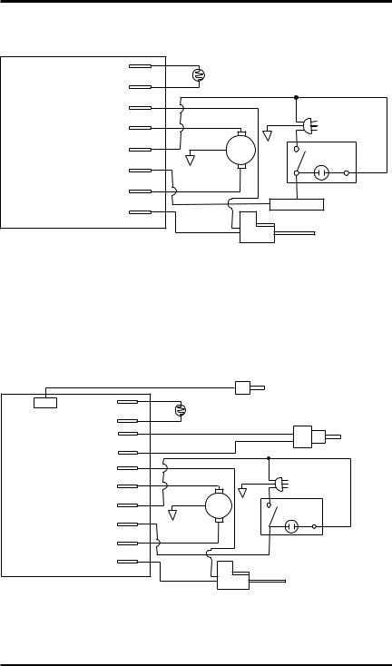
WIRING DIAGRAMS
MODELS RH125AT, M125AT, RH170AT, M170AT AND M200AT ONLY
Ignition Control Assembly
Photocell
Photocell
Ignitor
Motor Return
AC Neutral (L2)
120V (L1)
Motor
Ignitor
Blue
Blue |
Photocell |
|
|
|
|
|
|
|
|
White |
|
|
|
|
|
|
|
|
|
|
|
White |
|
Green |
Power Plug |
||
|
|
|
|
Black |
120V/60Hz |
|
|
Green |
Motor |
|
|
|
|
|
|
5 |
|
|
||
|
|
|
Yellow |
|
|
|
|
|
|
4 |
|
1 |
|
|
|
|
|
|
||
|
|
|
|
|
|
|
|
Red |
|
|
Black |
|
ON/OFF Switch |
|
Black |
|
|
|
||
|
|
|
Thermostat |
with Light |
||
|
|
|
|
|
||
|
Yellow |
Ignitor |
|
|
|
|
|
|
|
|
|
|
|
125T MODELS: RHD125AT, RL125AT, RE125AT, PKHD125T, TKU125T, UKU125T, RD125T
170T MODELS: RHD170AT, RL170AT, RE170AT, PKHD170T, TKU170T, UKU170T, RD170T
200T Models: RHD200AT, RE200AT, RH200AT, RL200AT, PKHD200T, TKU200T, UKU200T, RD200T
Control Assembly |
113471-01 |
Ignition |
|
Photocell
Photocell
Temp.
Temp.
Ignitor
Motor Return
AC Neutral (L2)
120V (L1)
Motor
Ignitor
|
Temperature |
Blue |
Sensor |
|
|
Blue |
Photocell |
|
|
|
Thermostat |
|
Control |
|
White |
White |
Green |
Green Motor |
Black |
5 |
|
|
Yellow/T |
4
Red
Black
Power Plug
120V/60Hz
1
ON/OFF Switch
with Light
Yellow/T Ignitor
16 |
www.desatech.com |
113170-01E |
TECHNICAL SERVICE
You may have further questions about installation, operation or troubleshooting. If so, contact DESA Heating Productsʼ Technical Service Department at 1-866-672-6040.When calling please have your model and serial numbers of your heater ready.
You can also visit DESAHeating Productsʼtechnical services web site at www.desatech.com.
ACCESSORIES
Purchase accessories and parts from your nearest dealer or service center. If they can not supply these accessories or parts, either contact your nearest parts dealer or DESA Heating Products at 1-866-672-6040 for referral information. Parts CentralsarelistedintheAuthorizedServiceCenter booklet supplied with heater.
REPLACEMENT PARTS
Note: Use only original replacement parts. This will protect your warranty coverage for parts replaced under warranty.
PARTS UNDER WARRANTY
Contact authorized dealers of this product. If they canʼt supply original replacement part(s), call DESAHeating ProductsʼTechnical Service Dept. at 1-866-672-6040.
When calling DESA Heating Products, have ready:
•your name
•your address
•model and serial numbers of your heater
•how heater was malfunctioning
•purchase date
Usually, we will ask you to return the part to the factory.
PARTS NOT UNDER WARRANTY
Contact authorized dealers of this product. If they canʼt supply original replacement part(s), call DESA Heating Products at 1-866-672-6040 for referral information. Parts dealers are listed in the Authorized Service Center booklet supplied with heater.
When calling DESA Heating Products, have ready:
•model and serial numbers of your heater
•the replacement part number
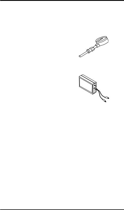
AIR GAUGE KIT - HA1180
For all models. Special tool to check pump pressure.
IGNITION CONTROL ASSEMBLY/ PHOTOCELL TESTER - HA1170
For all models. Special tool used to test the ignition control assembly and photocell.
113170-01E |
www.desatech.com |
17 |

ILLUSTRATED PARTS BREAKDOWN
125T MODELS:
RH125AT, RHD125AT, RL125AT, M125AT, RE125AT, PKHD125T, TKU125T, UKU125T, RD125T
170T MODELS:
RH170AT, RHD170AT, RL170AT, M170AT, RE170AT, PKHD170T, TKU170T, UKU170T, RD170T
13 |
|
3 |
1 |
|
9
710
4 |
5 |
|
|
|
6 |
|
8 |
11 |
|
|
|
|
||
|
23 |
19 |
|
|
24 |
|
|
12 |
|
|
|
|
15 |
23 |
|
|
13 |
25 |
|
|
|
|
34 |
|
31 |
|
|
26 |
|
|
|
|
|
|
|
20 |
29 |
|
|
|
|
|
||
32 |
21 |
22 |
|
|
|
|
|
||
|
|
|
|
36 |
|
|
|
|
28 |
18 |
|
|
|
|
|
|
|
|
14 |
|
|
|
|
13 |
|
|
|
|
16 |
30 |
|
|
|
|
|
|
|
|
2 |
|
|
|
27 |
|
|
|
35 |
|
33 |
|
|
|
|
|
17

18 |
www.desatech.com |
113170-01E |
 Loading...