


 Loading...
Desa VUM50SR, VUM36SR, VCM-42U, VCM-36U, VUM42SR User Manual
...UNVENTED (VENT-FREE) UNIVERSAL FIREBOX OWNER’S OPERATION AND INSTALLATION MANUAL
Models (V)Um36(Sr,SI,HR,HI), VCM-36U, (V)Um42(Sr,SI,HR,HI),
VCM-42U, (V)Um50(Sr,SI,HR,HI), VCM-50U
 WARNING: If the information in this manual is not followedexactly, a fire orexplosion may resultcausing property damage, personal injury or loss of life.
—Do not store or use gasoline or other flammable vapors and liquids in the vicinity of this or any other appliance.
—WHAT TO DO IF YOU SMELL GAS
•Do not try to light any appliance.
•Donottouchanyelectricalswitch;donotuseany phone in your building.
•Immediatelycallyourgassupplierfromaneighbor’s phone. Follow the gas supplier’s instructions.
•If you cannot reach your gas supplier, call the fire department.
—Installationandservicemustbeperformedbyaqualified installer, service agency or the gas supplier.
INSTALLER: Leave this manual with the appliance. CONSUMER: Retain this manual for future reference.
For more information, visit www.desatech.com
 WARNING: Improper installation, adjustment, alteration, service or maintenance can cause injury or property damage. Refer to this manual for correct installation and operational procedures. For assistance or additional information consult a qualified installer, service agency or the gas supplier.
 WARNING: Carefully review the instructions supplied with the decorative type unvented room heater for the minimum fireplace size requirement.
Do not install the appliance in this firebox, unless this firebox meets the minimum dimensions required for the installation.
 WARNING: For use only with a listed, gasfired unvented decorative room heater not to exceed 40,000 Btu/H.
Do not build a wood fire.
TABLE OF CONTENTS
Safety................................................................... |
2 |
Installation.......................................................... |
10 |
Local Codes......................................................... |
4 |
Technical Service............................................... |
23 |
Product Features.................................................. |
4 |
Replacement Parts............................................. |
23 |
Locating Firebox................................................... |
4 |
Parts................................................................... |
24 |
Product Specifications.......................................... |
5 |
Warranty............................................... |
Back Cover |
Air For Combustion and Ventilation...................... |
8 |
|
|
Safety
This appliance may be installed in an aftermarket,* permanently located, manufactured (mobile) home, where not prohibited by local codes.
* Aftermarket: Completion of sale, not for purpose of resale, from the manufacturer
This firebox has been tested under Z21.91b-2004 for use with approved ANSI Z21.11.2 decorative type unvented room heater.
IMPORTANT: Read this owner’s manualcarefullyandcompletely before trying to assemble, operate or service this fireplace. Improper use of this fireplace can cause serious injury or death from burns, fire, explosion,electricalshockandcarbon monoxide poisoning.
 DANGER:Carbonmonoxide
poisoning may lead to death!
2 |
www.desatech.com |
122274-01F |
Safety
Continued
 WARNING: Any change to this firebox or its controls can be dangerous.
 WARNING: Do not allow fans to blow directly into the firebox.
Avoidanydraftsthatalterburner flame patterns. Ceiling fans can create drafts that alter burner flame patterns. Altered burner patterns can cause sooting.
 WARNING:Donotuseablower insert, heat exchanger insert orotheraccessorynotapproved for use with this firebox.
Due to high temperatures, the applianceshouldbelocatedout oftrafficandawayfromfurniture and draperies.
Do not place clothing or other flammable material on or near the appliance. Never place any objects in the firebox or on logs.
Firebox front and screen becomes very hot when running firebox.Keepchildrenandadults away from hot surfaces to avoid burns or clothing ignition. Firebox will remain hot for a time after shutdown. Allow surfaces to cool before touching.
Carefully supervise young children when they are in the room with firebox.
Keepthefireplaceareaclearand freefromcombustiblematerials, gasoline, and other flammable vapors and liquids.
You must operate this fireplace with the provided fireplace screen and hood in place. Make sure these parts are in place and screens are closed before runninginstalledgaslogheater.
Replace hood with DESA Heating, LLC model 109511-01 50", 109511-02 42", or 109511-03 36" only. This hood has been designed to keep the operation of your fireplace safe and efficient.
1.Do not use this firebox as a wood burning fireplace. Use only decorative unvented room heaters (log sets).
2.Do not add extra logs or ornaments such as pinecones,vermiculiteorrockwool.Using these added items can cause sooting.
3.Use only the provided hood. See Parts, page 30.
4.Vent-free gas log heaters installed in these fireboxes require fresh air ventilation to run properly. See Air for Combustion and Ventilation, page 8.
5.Do not run vent-free heaters installed in these fireboxes
•where flammable liquids or vapors are used or stored
•under dusty conditions
6.Do not use this firebox to cook food or burn paper or other objects.
7.Turn unit off and let cool before servicing.
Only a qualified service person should service and repair firebox.
8.Operating vent-free heaters installed in these fireboxes above elevations of 4,500 feet could cause pilot outage.
9.Do not use the firebox if it has been under water.
10.Before using furniture polish, wax, carpet cleaner or similar products, turn heater off. If heated, the vapors from these products may create a white powder residue within burner box or on adjacent walls and furniture.
11.Provide adequate clearances around air openings.
122274-01F |
www.desatech.com |
3 |

Local Codes
Install and use firebox with care. Follow all local codes. In the absence of local codes, use the latest edition of The National Fuel Gas Code ANSI Z223.1/NFPA 54*. Firebox must be electrically grounded in accordance with the National Electrical Code, ANSI/NFPA70
(latest edition).
*Available from:
American National Standards Institute, Inc.
1430 Broadway
New York, NY 10018
National Fire Protection Association, Inc.
Batterymarch Park
Quincy, MA 02269
State of Massachusetts: The installation must be made by a licensed plumber or gas fitter in the Commonwealth of
Massachusetts.
Sellers of unvented propane or natural gas-fired supplemental room heaters shall provide to each purchaser a copy of 527 CMR 30 upon sale of the unit.
Vent-free gas products are prohibited for bedroom and bathroom installation in the Commonwealth of Massachusetts.
Product Features
Operation
This firebox is designed for use with approved
ANSI Z21.11.2 decorative type unvented room heaters. (Physical size limitations apply. Refer to minimum firebox requirements supplied with log heater.) It requires no outside venting or chimney making installation easy and inexpensive.
Locating Firebox
Planning
Plan where you will install the firebox.This will save time and money later when you install the firebox. Before installation, consider the following:
1.Where firebox will be located. Allow for wall and ceiling clearances (see Installation Clearances, page 11).
2.Everything needed to complete installation.
3.These models CANNOT be installed in a bedroom unless maximum Btu rating of installed vent-free log set is less than 10,000 Btu/hr.
4.Proper air for combustion and ventilation (page 8).
4 |
www.desatech.com |
122274-01F |

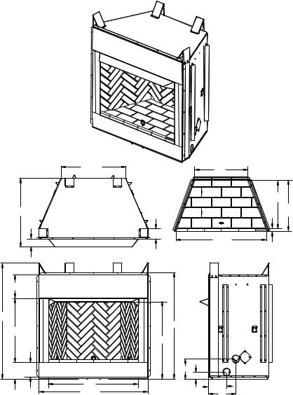
Product Specifications
36" Models (V)UM36 Series and VCM-36U
|
|
29" |
|
22" |
|
30 |
1 |
/2" |
|
|
18 3/8" 19 13/16" |
|
|
|
(Ref.) |
||
|
|
|
|
|
|
|
|
4 |
7/8" |
34 3/4" |
1 5/16" |
|
|
3 3/4" |
|
||
|
|
|
36" HEARTH |
|
|
|
|
|
|
|
11 1/8"
54 1/2"
50"
30"
|
|
|
|
365/16" |
7 |
7 |
/8" |
7" |
97/16" |
|
|
35/16" |
||
|
|
|
|
|
|
|
|
36" |
7 3/8" |
|
|
|
45 1/8" |
111/8" |
Figure 1 - 36" Models (V)UM36 Series and VCM-36U
122274-01F |
www.desatech.com |
5 |
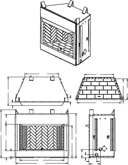
Product Specifications
Continued
42" Models (V)UM42 Series and VCM-42U
30 |
5/16" |
25" |
|
|
|
|
|
|
|
|
22 1/2" |
32 3/8" |
|
|
23 13/16" |
|
|
(Ref.) |
|
|
|
|
|
|
|
4 7/8" |
|
3 3/4" |
|
40 3/4" |
1 5/16" |
|
|
42" HEARTH |
|
|
|
|
11 1 /8"
54 1/2"
|
50" |
30" |
|
|
36 5/16" |
7 7/8" 7" |
9 7/16" |
|
3 5/16" |
42" |
8 3/4" |
51 1/8" |
13" |
Figure 2 - 42" Models (V)UM42 Series and VCM-42U
6 |
www.desatech.com |
122274-01F |
Product Specifications
Continued
50" Models (V)UM50 Series and VCM-50U
38 |
5/16" |
33" |
|
|
|
|
|
|
|
|
22 1/2" |
32 3/8" |
|
|
23 13/16" |
|
|
(Ref.) |
|
|
|
|
|
|
|
4 7/8" |
|
3 3/4" |
|
40 3/4" |
1 5/16" |
|
|
50" HEARTH |
|
|
|
|
|
11 1/8" |
|
|
|
54 1/2" |
|
50" |
|
30" |
|
|
|
|
|
|
|
|
|
365/16" |
|
7 7/8" 7" |
|
97/16" |
|
|
|
35/16" |
|
50" |
|
8 3/4" |
|
59 1/8" |
13" |
|
|
Figure 3 - 50" Models (V)UM50 Series and VCM-50U
122274-01F |
www.desatech.com |
7 |

Air For Combustion and Ventilation
 WARNING: This heater shall notbeinstalledinaroomorspace unlesstherequiredvolumeofindoor combustion air is provided by the method described in the
National Fuel Gas Code, ANSI Z223.1/NFPA54,theInternational Fuel Gas Code, or applicable localcodes.Readthefollowinginstructionstoinsureproperfresh airforthisandotherfuel-burning appliances in your home.
Today’s homes are built more energy efficient than ever. New materials, increased insulation and new construction methods help reduce heat loss in homes. Home owners weather strip and caulk around windows and doors to keep the cold air out and the warm air in. During heating months, home owners want their homes as airtight as possible.
While it is good to make your home energy efficient, your home ne eds to breathe. Fresh air must enter your home. All fuel-burning appliances need fresh air for proper combustion and ventilation.
Exhaust fans, fireplaces, clothes dryers and fuelburningappliancesdrawairfromthehouse to operate. You must provide adequate fresh air for these appliances. This will insure proper venting of vented fuel-burning appliances.
PROVIDING ADEQUATE VENTILATION
The following are excerpts from National Fuel Gas Code, ANSI Z223.1/NFPA 54, Air for Combustion and Ventilation.
All spaces in homes fall into one of the three following ventilation classifications:
1.Unusually Tight Construction
2.Unconfined Space
3.Confined Space
Theinformationonpages8 through 10 willhelp you classify your space and provide adequate ventilation.
Unusually Tight Construction
The air that leaks around doors and windows may provide enough fresh air for combustion and ventilation. However, in buildings of unusually tight construction, you must provide additional fresh air.
Unusually tight construction is defined as construction where:
a.walls and ceilings exposed to the outside atmosphere have a continuous water vapor retarder with a rating of one perm (6 x 10-11 kg per pa-sec-m2) or less with openings gasketed or sealed and
b.weather stripping has been added on openable windows and doors and
c.caulking or sealants are applied to areas such as joints around window and door frames, between sole plates and floors, between wall-ceiling joints, between wall panels, at penetrations for plumbing, electrical and gas lines and at other openings.
If your home meets all of the three criteria above, you must provide additional fresh air. See Ventilation Air From Outdoors, page 10.
If your home does not meet all of the three criteria above, proceed to Determining Fresh-Air Flow For Firebox Location.
Confined and Unconfined Space
The National Fuel Gas Code, ANSI Z223.1/ NFPA 54 defines a confined space as a space whose volume is less than 50 cubic feet per
1,000 Btu per hour (4.8 m3 per kw) of the aggregate input rating of all appliances installed in that space and an unconfined space as a space whose volume is not less than 50 cubic feet per 1,000 Btu per hour (4.8 m3 per kw) of the aggregate input rating of all appliances installed in that space. Rooms communicating directly with the space in which the appliances are installed*, through openings not furnished with doors, are considered a part of the unconfined space.
* Adjoining rooms are communicating only if there are doorless passageways or ventilation grills between them.
determining fresh-air flow for Firebox location
Determining if You Have a Confined or Unconfined Space
Use this work sheet to determine if you have a confined or unconfined space.
Space: Includes the room in which you will install heater plus any adjoining rooms with doorless passageways or ventilation grills between the rooms.
8 |
www.desatech.com |
122274-01F |
Air for combustion and ventilation
Continued
1.Determine the volume of the space (length x width x height).
Length x Width x Height =__________cu. ft. (volume of space)
Example: Space size 22 ft. (length) x 18 ft.
(width) x 8 ft. (ceiling height) = 3,168 cu. ft.
(volume of space)
If additional ventilation to adjoining room is supplied with grills or openings, add the volume of these rooms to the total volume of the space.
2.Multiply the space volume by 20 to determine the maximum Btu/Hr the space can support.
_ ________ (volume of space) x 20 = (Maximum Btu/Hr the space can support)
Example: 3,168 cu. ft. (volume of space) x 20 = 63,360 (maximum Btu/Hr space can support)
3.Add the Btu/Hr of all fuel burning appliances in the space.
If the actual Btu/Hr used is less than the maximum Btu/Hr the space can support, the space is an unconfined space. You will need no additional fresh air ventilation.
 WARNING:Iftheareainwhich theheatermaybeoperateddoes notmeettherequiredvolumefor indoorcombustionair,combustion and ventilation air shall be provided by one of the methods described in the National Fuel GasCode,ANSIZ223.1/NFPA54, the International Fuel Gas Code, or applicable local codes.
Vent-free fireplace |
__________ Btu/Hr |
Gas water heater* |
__________ Btu/Hr |
Gas furnace |
__________ Btu/Hr |
Vented gas heater |
__________ Btu/Hr |
Gas fireplace logs |
__________ Btu/Hr |
Other gas appliances* +__________ Btu/Hr Total =__________ Btu/Hr
* Do not include direct-vent gas appliances.
Direct-vent draws combustion air from the outdoors and vents to the outdoors.
Example: |
|
|
|
Gas water heater |
|
40,000 |
Btu/Hr |
Vent-free fireplace |
+ |
39,000 |
Btu/Hr |
Total |
= |
79,000 |
Btu/Hr |
4.Compare the maximum Btu/Hr the space can support with the actual amount of Btu/Hr used.
_ _______ Btu/Hr (maximum the space can support)
_ _______ Btu/Hr (actual amount of Btu/Hr used)
Example: 63,360 Btu/Hr (maximum the space can support)
79,000 Btu/Hr (actual amount of Btu/Hr used)
The space in the example is a confined space because the actual Btu/Hr used is more than the maximum Btu/Hr the space can support. You must provide additional fresh air. Your options are as follows:
A.Rework worksheet, adding the space of an adjoining room. If the extra space provides an unconfined space, remove door to adjoining room or add ventilation grills between rooms.
See Ventilation Air From Inside Building.
B.Vent room directly to the outdoors. See
Ventilation Air From Outdoors, page 10.
C.Install a lower Btu/Hr fireplace, if lower Btu/ Hr size makes room unconfined.
VENTILATION AIR
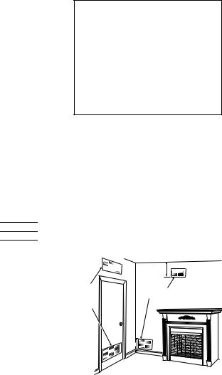
Ventilation Air From Inside Building
This fresh air would come from an adjoining unconfined space. When ventilating to an adjoining unconfined space, you must provide two permanent openings: one within 12" of the ceiling and one within 12" of the floor on the wall connecting the two spaces (see options 1 and 2, Figure 4). You can also remove door into adjoining room (see option 3, Figure 4 ).
Follow the National Fuel Gas Code, ANSI Z223.1/NFPA 54, Air for Combustion and Ventilation for required size of ventilation grills or ducts.
|
|
12" |
|
Ventilation |
|
Ventilation Grills |
|
Grills Into |
|
||
Adjoining |
Or |
Into Adjoining Room, |
|
Room, |
Option 2 |
||
Remove |
|||
Option 1 |
|
||
Door into |
|
||
|
|
||
|
Adjoining |
|
|
|
Room, |
|
|
|
Option |
|
|
|
3 |
|
|
|
|
12" |
Figure 4 - Ventilation Air from Inside Building
122274-01F |
www.desatech.com |
9 |
air for combustion and ventilation
Continued
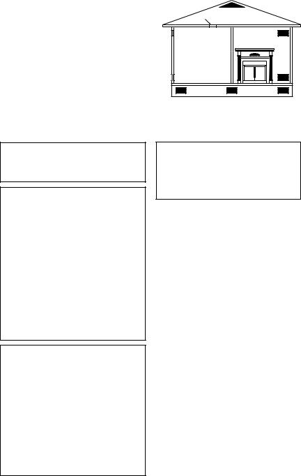
Ventilation Air From Outdoors
Provide extra fresh air by using ventilation grills or ducts. You must provide two permanent openings: one within 12" of the ceiling and one within 12" of the floor. Connect these items directly to the outdoors or spaces open to the outdoors. These spaces include attics and crawl spaces. Follow the National Fuel Gas Code, ANSI Z223.1/NFPA 54, Air for Combustion and Ventilation for required size of ventilation grills or ducts.
IMPORTANT: Do not provide openings for inlet or outlet air into attic if attic has a thermo- stat-controlled power vent. Heated air entering the attic will activate the power vent.
Outlet |
|
Ventilated |
|
Attic |
|
Air |
|
|
|
|
|
|
|
|
Outlet |
|
|
Air |
|
To Attic |
|
|
|
|
|
To |
|
|
Crawl |
Inlet |
|
Space |
|
|
|
Air |
|
|
|
Inlet Air |
Ventilated |
|
Crawl Space |
|
|
|
Figure 5 - Ventilation Air from Outdoors
Installation
 WARNING: A qualified servicepersonmustinstallfirebox. Follow all local codes.
 WARNING: Never install firebox
•in a bedroom or bathroom*
•in a recreational vehicle
•where curtains, furniture, clothing, or other flammable objects are less than 36" from frontor42"fromtopoffirebox; forsideclearancesseeFigure 4, page 11
•in high traffic areas
•in windy or drafty areas
*Unlessinstalledlogsetisrated at 10,000 Btu/Hr or less.
 CAUTION: Log heaters installed in this firebox create warmaircurrents.Thesecurrents move heat to wall surfaces next to firebox. Installing firebox next tovinylorclothwallcoveringsor operating firebox where impurities(suchas,butnotlimitedto,tobacco smoke, aromatic candles, cleaning fluids, oil or kerosene lamps, etc.) in the air exist, may discolor walls or cause odors.
NOTICE: The firebox identificationlabel(includingmodelnumber, serial number, clearances, etc.) is located on a chain under the bottom refractory.
IMPORTANT: Vent-free gas log heaters add moisture to the air.Although this is beneficial, installing firebox in rooms without enough ventilation air may cause mildew to form from too much moisture. See, page 8.
IMPORTANT: Make sure the firebox is level. If firebox is not level, log set will not work properly.
Note: Your firebox is designed to be used in zero clearance installations. Wall or framing material can be placed against any exterior surface on the rear, sides, top or bottom of your firebox, except where standoff spacers are integrally attached. If standoff spacers are attached to your firebox, these spacers can be placed directly against wall or framing materials. Use the dimensions shown for rough opening to create the easiest installation.
Use dimensions shown for rough openings to create the easiest installation (see Built-In Firebox Installation, page 12).
10 |
www.desatech.com |
122274-01F |
Installation
Continued
INSTALLATION CLEARANCES
 WARNING: Maintain the minimum clearances. If you can, provide greater clearances from floor, ceiling, and adjoining wall.
Carefully follow the instructions below. This will ensure safe installation.
Minimum Wall and Ceiling Clearances (see Figure 6)
A.Clearances from the side of the fireplace cabinet to any combustible material and wall should follow diagram in Figure 6.
Example: The face of a mantel, bookshelf, etc. is made of combustible material and protrudes 3 1/2" from the wall. This combustible material must be 4" from the side of the fireplace cabinet (see Figure 4).
B.Clearances from the top of the firebox opening to the ceiling should not be less than 42".
C.When the firebox is installed directly on carpeting, tile or other combustible material, other than wood flooring, the firebox should be installed on a metal or wood panel extending the full width and depth of the enclosure.
Mantel Clearances for Built-In Installation
If placing custom mantel above built-in firebox, you must meet the minimum allowable clearance between mantel shelf and top of firebox opening shown in Figure 7. These are the minimum allowable mantel clearances for a safe installation. Use larger clearances wherever possible to minimize the heating of objects and materials placed on the mantel.
 CAUTION: Do not allow the vent-freegaslogheatertotouch or extend beyond the fireplace screen.
NOTICE: Surface temperatures of adjacent walls and mantels become hot during operation. Walls and mantels above the firebox may become hot to the touch. If installed properly, these temperatures meet the requirement of the national product standard. Follow all minimum clearances shown in this manual.
D.Clearances from the bottom of firebox to the floor is 0".
These fireboxes can be installed as freestanding units against a wall with approved cabinet mantels that may be available from your retailer or supplier, or as a built-in unit. The clearances are the same for either installation method.
Example |
* |
Wall board or facing material (above firebox) may be of combustible material, including decorative mantel ornaments or other similar projections off of the facing material.
Framing
Material
Firebox
Wire-mesh
Screen
Mantel Shelf
Note: Any portion of the mantel shelf must NOT
extend beyond this profile.
12"
6 3/4"
1 1/2"
|
|
|
|
|
|
|
|
|
|
Note: All vertical |
|
Supplied |
measurements are |
||
from top of fireplace |
|||
Firebox Hood |
hood opening to |
||
|
Noncombustible |
||
|
Material May |
||
|
Project Off this 12" 16" 20" |
||
|
Surface above |
||
|
the Firebox Hood |
||
Must Be Used bottom of mantel shelf. |
|
at All Times |
These minimum |
|
|
|
clearances replace any |
|
other recommended |
|
clearances supplied |
|
with your ANSI Z21.11.2 |
|
approved gas logs. |
|
|
Figure 7 - Minimum Mantel Clearances |
|
*Minimum 16" from Side Wall |
|||
for Built-In Installation |
|||
Figure 6 - Minimum Clearance for |
|||
|
|||
Combustible to Wall |
|
||
122274-01F |
www.desatech.com |
11 |
Loading...