


DIRECT-VENT FIREPLACE
OWNER’S OPERATION AND
INSTALLATION MANUAL
DEDICATED REAR ANDTOPVENT FIREPLACES
MODELS: (V) CD36R(N,P) (E) MODELS: (V) CD36T(N,P) (E)
WARNING: If the information in this manual is not followed exactly, a fire or explosion may result causing property damage, personal injury, or loss of life.
FORYOUR SAFETY
Do not store or use gasoline or other flammable vapors and liquids in the vicinity of this or any other appliance.
FORYOUR SAFETY
WHATTO DO IFYOU SMELL GAS
•Do not try to light any appliance.
•Do not touch any electrical switch.
•Do not use any phone in your building.
•Immediatly call your gas wupplier from a neighbor’s phone. Follow the gas supplier’s instructions.
•If you cannot reach your gas supplier, call the fire department.
WARNING: Improper installation adjustment, alteration, service, or maintenance can cause injury or property damage. Refer to this manualforcorrectinstallationand operational procedures. For assistanceoradditionalinformation consult a qualified installer, service agency, or the gas supplier.
Installation and service must be performed by a qualified installer, service agency, or the gas supplier.
This appliance may be installed in an aftermarket*, permanently located, manufactured (modile) home, where not prohibited by state or local codes.
This appliance is only for use with the type od gas indicated on the rating plate.This appliance is not convertible for use with other gases, unless a certified kit is used.
*Aftermarket: Completion of sale, not for purpose of resale, from the manufacturer.
State of Massachusetts:The installation must be made by a licensed plumber or gas fitter in the Commonwealth of Massachusetts.
Save this manual for future reference. For more information, visit www.desatech.com
SAFETY INFORMATION
 WARNING: This product contains and/or generates chemicals known to the State of California to cause cancer or birth defects, or other reproductive harm.
IMPORTANT: Read this owner’s manual carefully and completely before trying to assemble, operate, or service this fireplace. Improper use of this fireplace can cause serious injury or death from burns, fire, explosions, electrical shock, and carbon monoxide poisoning.
 DANGER: Carbon monoxide poisoning may lead to death!
This fireplace must be installed by a qualified (certified or licensed) service person. It has a sealed gas combustion chamber that uses a coaxial pipe (pipe within a pipe and having the same center) venting system. It brings in fresh air for combustion through the outer pipe and combustion gases are exhausted through the inner pipe. If the glass door assembly and venting pipe are not properly seated, connected, and sealed, carbon monoxide leakage (spillage) can occur.
Carbon Monoxide Poisoning: Early signs of carbon monoxide poisoning resemble the flu, with headaches, dizziness, or nausea. If you have these signs, the fireplace may not have been installed properly. Get fresh air at once! Have fireplace inspected and serviced by a qualified service person. Some people are more affected by carbon monoxide than others. These include pregnant women,peoplewithheartorlungdiseaseoranemia,thoseunderthe influence of alcohol, and those at high altitudes.
Propane/LPandNaturalGas:Propane/LPandnaturalgasesare oderless.An odor-making agent is added to the gas. The odor helps you detect a gas leak. However, the odor added to the gas can fade. Gas may be present even though no odor exists.
Make certain you read and understand all warnings. Keep this manual for reference. It is your guide to safe and proper operation of this fireplace.
 WARNING: Any change to this fireplace or its controls can be dangerous.
1.This appliance is only for use with the type of gas indicated on the rating plate. This appliance is not convertible for use with other gases unless a certified kit is used.
2.For a propane/LP fireplace, do not place propane/LP supply tank(s) inside any structure. Locate propane/LP tank(s) outdoors. To prevent performance problems, do not use propane/LP fuel tank of less than 100 lbs. capacity.
3.If you smell gas:
•shut off gas supply
•do not try to light any appliance
•do not touch any electrical switch; do not use any phone in your building
•immediately call your gas supplier from a neighbor’s phone. Follow the gas supplier’s instructions
•ifyoucannotreachyourgassupplier,callthefiredepartment.
4.Never install the fireplace
•in a recreational vehicle
•in windy or drafty areas where curtains or other combustible (flammable)objectscanmakecontactwiththefireplacefront
•in high traffic areas
www.desatech.com |
116035-01B |
SAFETY INFORMATION
PRODUCT IDENTIFICATION 3 LOCAL CODES
SAFETY INFORMATION
Continued
5.This fireplace reaches high temperatures, Keep children and adults away from hot surfaces to avoid burns or clothing ignition. Fireplace will remain hot for a time after shutdown. Allow surfaces to cool before touching.
6.Carefully supervise young children when they are in the room with fireplace.
7.Do not modify this fireplace under any circumstances. Any parts removed for servicing must be replaced prior to operating fireplace.
8.Turn fireplace off and let cool before servicing, installing, or repairing. Only a qualified service person should install, service or repair this fireplace. Have fireplace inspected annually by a qualified service person.
9.You must keep control compartments, burners, and circulating air passages clean. More frequent cleaning may be needed due to excessive lint and dust from carpeting, bedding material, etc. Turn off the gas valve and pilot light before cleaning fireplace.
10.Have venting system inspected annually by a qualified service person. If needed, have venting system cleaned or repaired. See Cleaning and Maintenance, page##.
11.Keep the area around your fireplace clear of combustible materials, gasoline, and other flammable vapor and liquids. Do not run fireplace where these are used or stored. Do not place items such as clothing or decorations on or around fireplace.
12.Do not use this fireplace to cook food or burn paper or other objects.
13.Do not use any solid fuels (wood, coal, paper, cardboard, etc.) in this fireplace. Use only the gas type indicated on the nameplate.
14.This appliance, when installed, must be electrically grounded inaccordancewithlocalcodesor,intheabsenceoflocalcodes, with the National Electric Code, ANSI/NFPA 70, or the Canadian Electric Code, CSA C22.1.
15.Do not use fireplace if any part has been exposed to or under water. Immediately call a qualified service person to arrange for replacement of the unit.
16.Do not operate fireplace if any log is broken or missing.
17.Do not use a blower insert, heat exchanger insert, or other accessory not approved for use with this fireplace.
18.Do not operate fireplace with glass door removed, cracked, or broken.
19.Provide adequate clearances around air openings.
 NOTICE:This product is intended only as a supplement to your central heating system and is not to be installed as a primary source of heat.You may use this product for emergency heating during a power outage.
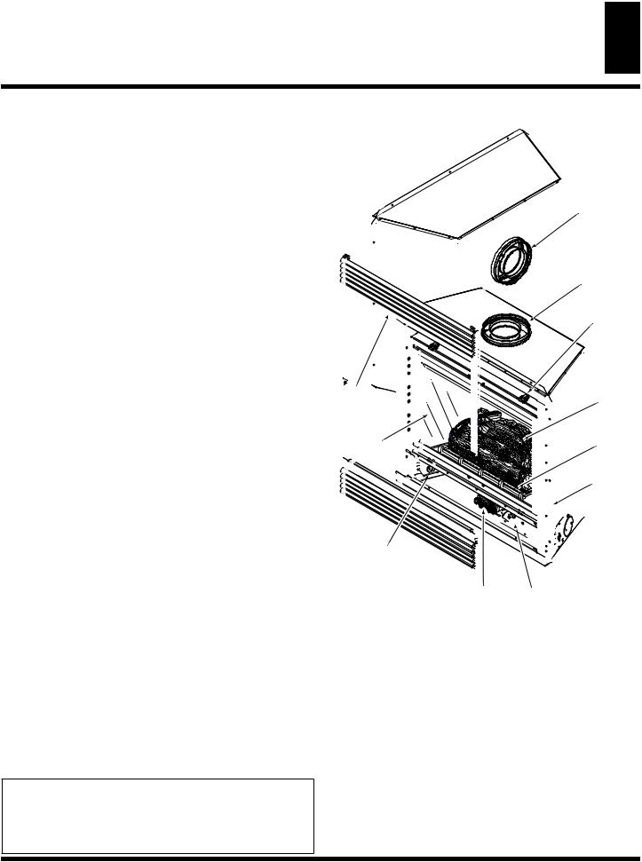
PRODUCT IDENTIFICATION
Rear Vent
Flue Collar
Top Vent
Flue Collar
Door Latch
Upper |
Log |
|
Louver |
||
Set |
||
Panel |
||
|
||
Glass |
Ember |
|
Door |
||
Assembly |
Tray |
|
|
Nailing |
|
|
Flange |
Lower 
Louver
Panel
Junction Box
Control Valve |
Piezo Ignitor with |
Variable Input |
Optional Remote and |
Adjustment |
Blower Control Mount |
Figure 1 - Rear /Top Direct-Vent Fireplace
LOCAL CODES
Install and use fireplace with care. Follow all local codes. In the absence of local codes, use the current National Fuel Gas Code ANSI Z223.1/NFPA 54* (USA) or the current CSA-B149.1 Installation Code (Canada).
*Available from:
American National Standards Institute, Inc.
1430 Broadway
New York, NY 10018
National Fire Protection Association, Inc.
Batterymarh Park
Quincy, MA 02269
116035-01B |
www.desatech.com |
PRODUCT FEATURES
4 PRE-INSTALLATION PREPARATION
Location and Space Requirements
PRODUCT FEATURES
These are a few facts that can help you understand and enjoy your direct-vent fireplace:
•The CD36R dedicated rear vent is best suited for flush or corner installations when vented horizontally through an exterior wall.
•The CD36T dedicated top vent is suited for any application where height is necessary to terminate the venting system either through the roof (vertical) or to gain sufficient height and offset to vent to an outside/exterior wall (horizontal).
•The vent pipe installation is very important to allow for proper operation. You must select the appropriate unit for your application and follow the venting instructions to plan your installation.
•Thisfireplacemaybeinstalledinanyroomofyourhouseprovided all local codes and these installation instructions are followed.
•Models (V)CD36R/T are equipped with a millivolt gas control system that does not require electricity to operate. A piezo ignitor is provided to light the pilot without using matches or lighters.
•Models (V)CD36RE/TE are equipped with an electronic ignition system that requires 120VAC to operate. An electrode ignitor automatically lights the pilot flame when the fireplace is turned on.
•All models can accept an optional circulating air blower when 120VACconnectionissupplied.Ifyouplantoinstallanoptional blower, do not forget to wire the fireplace outlet when framing.
•Each time you turn on your fireplace, you may notice some amount of condensation on the inside of the fireplace glass.This is normal and will disappear after 10-20 minutes of operation.
•Your direct-vent gas fireplace system (fireplace and venting) is a balanced and sealed gas operating unit. It is highly efficient because it uses outside air for combustion while independantly heating the indoor air.
PRE-INSTALLATION
PREPARATION
LOCATION AND SPACE REQUIREMENTS
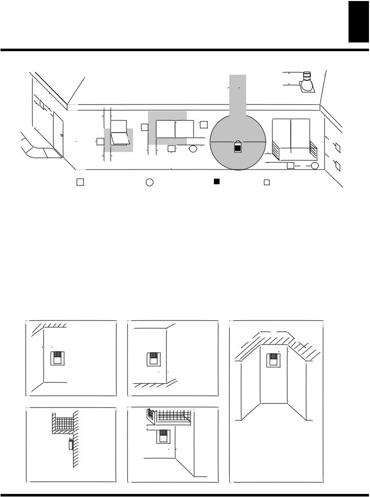
Determine the safest and most efficient location for your DESA direct-vent fireplace. Make sure that rafters and wall studs are not in the way of the venting system. Coose a location where the heat output is not affected by drafts, air conditioning ducts, windows or doors. Figure 2 shows some common locations. Be aware of all restrictions and precautions before deciding the exact location for your fireplace and termination cap.
When deciding the location of your fireplace, follow these rules:
• Do not connect this fireplace to a chimney flue servicing a separate solid-fuel burning fireplace or appliance.
•Do to high temperatures, do not locate this fireplace in high traffic areas, windy or drafty areas, or near furniture or draperies.
•Proper clearances must be maintained.
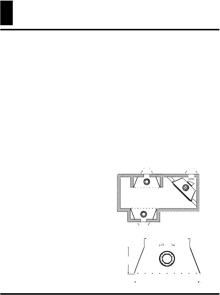
•If your fireplace is to be installed directly on carpeting, vinyl tile, or any combustible material other than wood, it must be installed on a metal or wood panel exttending the full width and depth of the fireplace. See Figure 3.
•Your fireplace is designed to be used in zero clearance installations. Wall or framing material can be placed directly against any exterior surface on the back, sides, or top of your fireplace, except where stand-off spacers are integrally attached. If standoff spacers are attached to your fireplace, these spacers can be placed directly against wall or framing material. See framing details on page 5.
•If you plan on installing a television or entertainment center recessed above your fireplace, it is recommended that you maintain a minimum 18” above the top of louver opening.
•When locating termination cap, it is important to observe the minimum clearances shown in Figure 10, page 7.
•If recessed into a wall, you can avoid extra framing b positioning your fireplace against an already existing framing member.
•Do not recess termination cap into a wall or siding.
•You may paint the termination cap with 450°F (232°C) heatresistant paint to coordinate with the exterior finish.
•There must not be any obstruction such as bushes, garden sheds, fences, decks, or utility buildings within 24” from the front of the termination cap.
•Do not locate termination cap where excessive snow or ice build up may occur. Be sure to clear vent terminal area after snow falls to prevent accidental blockage of venting system. When using snow blowers, do not direct snow towards vent termination area.
Flush with a wall |
|
Through exterior wall |
Corner |
enclosed in a chase |
Installation |
Figure 2 - Common Fireplace Locations
25" (635 mm)
15" (381 mm)
36"
(914 mm)
Figure 3 - Fireplace Bottom Dimensions
www.desatech.com |
116035-01B |
PRE-INSTALLATION PREPARATION
Clearances 5
Framing and Finishing
PRE-INSTALATION
PREPARATION
Continued
PACKAGING AND REMOVAL
The(V)CD36R/T directventgasfireplaceheaterispackagedwith:
-one box containg a 4-log set located on the burner in the firebox.
-one bag containing the owner’s manual with installation
instructions, operator’s guide, and warranty information.
-one bag of glowing ember material.
-one bag of vermiculite hearth treatments.
Remove the shrinkwrap securing the 2 carton trays to the unit. Lift the top carton tray off and remove the four corner posts. Discard the bottom tray once the unit is moved into position.
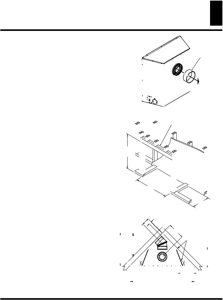
Note: On rear vent models you must remove the fiberboard collar protector located on the rear collar before installing the fireplace and venting system. See Figure 4.
CLEARANCES
Minimumclearancestocombustiblesforthefireplaceareasfollows:
Back, and sides |
0” (0 mm) |
Perpendicular walls |
12” (305 mm) |
Floor |
0” (0 mm) |
Ceiling to louver opening |
40” (1016 mm) |
Front |
36” (914 mm) |
Top |
0” (0 mm) |
Vent Surfaces |
1” (26 mm) (See venting instructions |
|
for specifics on vent clearances.) |
Mantel Clearances |
(See - Mantel Clearances for specific |
|
clearances to combustible mantels.) |
Combustible material with a maximum thickness of 5/8” (16 mm) may be flush with the top and sides of the front face of the fireplace.
FRAMING AND FINISHING
Figure 5 shows typical framing of this fireplace. Figure 6 shows framing for corner installation. All minimum clearances must be met.
For overall unit dimensions, framing allowances, and vent collar locations, see Unit Dimensions, Figure 9 on page 6.
For available accessories for this fireplace, see Accessories on page 37. If you are using a seperate combustible mantel piece, refer to Figures 7 and 8 for proper height and clearances. You can install a noncombustible mantel at any height above the fireplace opening. Note: Non-combustible mantels may discolor!
FIBERBOARD
COLLAR PROTECTOR
Figure 4 - Removing Collar Protector (Rear Vent) Fireplace
2x - VERTICAL
DOUBLE STUD
36" (914 mm)
36 1/4" (921 mm)
14 3/4" (375 mm)
Figure 5 - Framing Clearances for Flush,Wall Installation
|
2 1/2" (63 mm) |
THESE DIMENSIONS ALLOW |
|
6 5/8" ( 168 mm) |
MIN. 1" (26 mm) |
FOR 1" OF CLEARANCE |
|
|
AT THE SIDES AND BACK |
||
TO CENTER |
|
||
|
OF THE FIREPLACE |
||
OF REAR VENT |
|
||
14 3/4" |
HOWEVER, 0" CLEARANCE |
||
|
|||
|
|
IS ALSO PERMITTED AT |
|
|
|
ALL SIDES WHEN FRAMED |
|
21" (533 mm) |
|
|
|
TO CENTER OF |
|
|
|
TOP VENT |
|
|
|
28 5/8" |
|
14 3/4" |
|
(727 mm) |
|
||
|
(375 mm) |
||
|
|
||
|
|
TO NAILING |
|
|
|
FLANGES |
|
|
|
12 1/4" |
|
|
|
(311 mm) |
|
|
|
TO |
|
|
56 3/4" |
OPENING |
|
|
|
||
|
(1441 mm) |
|
Figure 6 - Framing Clearances for Corner Installation
116035-01B |
www.desatech.com |

UNIT DIMENSIONS
6 REAR /TOP VENT COMMON
CD36R, CD36T,VCD36R and VCD36T
MANTEL CLEARANCES
Figure 8 shows projected mantel depths at various heights above the top of the louver opening. Figure 7 shows the minimum allowable distances from various mantel components in relation to the both sides of the fireplace opening.
 WARNING:When finishing appliance, do not overlap combustible materials onto the black front face. Brick, tile, or other non-combustible materials may be applied to the face provided that any fireplace openings are not blocked and gaps in the material used and the face are sealed with a non-combustible caulking.
|
|
Outer Surround |
|
|
|
|
Combustible |
|
|
|
Material May |
|
|
|
Be Used |
1 1/2” |
|
SAFE |
|
|
ZONE |
|
|
(38 mm) |
|
|
|
6.0” |
|
|
|
|
|
33° |
|
(152 mm) |
|
||
|
|
||
5 1/2” |
|
|
|
(140 mm) |
|
|
|
|
3 3/4” |
|
|
To Fireplace (95 mm) |
12” |
Perpendicular |
|
Opening |
|
Side Wall |
|
|
|
(305 mm) |
|
|
|
|
|
Figure 7 - Side Clearances for Combustible Mantels
1 |
|
|
2 |
|
|
3 |
Stud Wall |
|
A |
||
|
||
4 |
|
B5
|
|
C |
|
6 |
|
|
|
|
|
|
|
|
D |
|
|
|
|
E |
7 |
|
|
|
|
|
|
|
|
F |
|
|
|
|
G |
|
|
|
|
Top of Louver Opening |
|
Ref. Mantel Depth |
Ref. Mantel from Top |
|
||
|
|
|
of Louver Opening |
|
1 |
16” (267mm) |
A |
14” (51mm) |
|
2 |
14” (229mm) |
B |
12” (51mm) |
|
3 |
12” (190mm) |
C |
10” (254mm) |
|
4 |
10” (152mm) |
D |
8” (203mm) |
|
5 |
8” (114mm) |
E |
6” (152mm) |
|
6 |
4” (76mm) |
F |
4” (102mm) |
|
7 |
2” (38mm) |
G |
2” (51mm) |
|
Figure 8 - Clearances for Combustible Mantels
2x Vertical
Header
@ 1” Min.
Clearance
5/8 Flue Pipe
UNIT DIMENSIONS
Rear /Top Vent Common
7 5/8" (194 mm) TO CENTER OF 8" TOP VENT
4" (102 mm) TO NAILING FLANGE
|
36 3/4" |
36 1/4" |
35 3/4" |
(921 mm) |
|
(908 mm) |
(934 mm) |
TO NAILING |
|
|
FLANGE |
WALL SWITCH |
|
|
WIREWAY |
|
|
|
4 1/2" |
|
|
(114 mm) |
|
8" (203 mm) |
ELECTRICAL |
|
INLET |
|
|
GAS SUPPLY |
|
|
|
|
|
INLET |
|
|
Figure 9 - Rear /Top Vent Common Dimensions
14 3/4"
(375 mm) TO NAILING FLANGES
38" |
|
|
(965 mm) |
2.0" |
|
2.0" |
5/8" |
|
(51 mm) |
(51 mm) |
|
|
|
(16 mm) |
36 1/4"
(921 mm) FACE DIM.
37" (940 mm) TO NAILING FLANGE
36" (914 mm) FACE DIM.
|
25" (635 mm) |
WALL SWITCH |
TO CENTER OF |
WIREWAY |
8" REAR VENT |
2.0 "
(51 mm)
2.5 " |
15 3/8" |
(63.5 mm) |
(390 mm) |
www.desatech.com |
116035-01B |
LOCATION OFTERMINATION CAP
7
LOCATION OFTERMINATION CAP
D |
|
|
|
|
H |
E |
|
|
|
|
|
V |
|
|
|
|
|
B |
C |
|
|
|
|
L |
|
|
|
|
|
|
Fixed |
V Openable |
B |
V |
|
|
Closed |
Fixed |
|
||
|
Openable |
|
|
Closed |
|
F |
|
|
|
B |
|
V |
|
|
|
||
|
|
B |
V |
J X |
G |
|
|
|
|
|
|
BA
V TERMINATION CAP |
X AIR SUPPLY INLET |
G GAS METER |
NN
 I
I
|
|
|
G |
|
|
|
V |
M |
K |
X |
G |
V |
V |
||
|
|
|
A |
 RESTRICTED AREA
  (TERMINATION PROHIBITED)
A = clearance above grade, veranda, porch, deck, or balcony [*12 inches (30.5mc) minimum]
B = clearance to window or door that may be opened [12 inches (30.5cm) minimum]
C = clearance to permanently closed window [minimum 12 inches (30.5cm) recommended to prevent condensation on window] D = vertical clearance to ventilated soffit located above the terminal
within a horizontal distance of 24 inches (61cm) from the center-line of the terminal [18 inches (45.7cm) minimum]
E = clearance to unventilated soffit [12 inches (30.5cm) minimum] F = clearance to outside corner (see below)
G = clearance to inside corner (see below)
H = *not to be installed above a meter/regulator assembly within
36 inches (91.4cm) horizontally from the center-line of the regulator
I = clearance to service regulator vent outlet [*72 inches (182.9cm) minimum]
J= clearance to non-mechanical air supply inlet to building or the combustion air inlet to any other fireplace [*12 inches (30.5cm)
minimum]
K= clearance to a mechanical air supply inlet [*72 inches (182.9cm) minimum]
L = clearance above paved side-walk or a paved driveway located on public property [*84 inches (213.3cm) minimum]
M = clearance under veranda, porch, deck [*12 inches (30.5cm) minimum ]
N= clearance above a roof shall extend a minimum of 24 inches (61cm) above the highest point when it passes through the roof surface and any other obstruction within a horizontal distance of 18 inches (45.7cm)
vent shall not terminate directly above a side-walk or paved driveway which is located between two single family dwellings and serves both dwellings*
only permitted if veranda, porch, deck or balconey is fully open on a minimum of 2 sides beneath the floor* * as specified in CAN/CSA B149 (.1 or .2) Installation Codes (1991) for Canada and U.S.A.
Note: Local codes or regulations may require different clearances
|
|
|
|
|
|
|
D |
|
|
C |
C |
A |
A = 6" (15.2cm) |
|
E |
|
|
|
|
V |
V |
|
V |
|
B |
B = 6" (15.2cm) |
|
|
|
|
|
H |
|
G |
V |
|
|
||
V |
J |
|
|
||
|
Combustible & |
|
|
Noncombustible |
|
G = 12" (30.5cm) minimum clearance |
H = 24" (61cm) |
|
J = 20" (50.8cm) |
||
|
C = Maximum depth of 48" (121.9cm) for recessed location
D = Minimum width for back wall of recessed location - Combustible - 38" (965mm) Noncombustible - 24" (61cm)
E = Clearance from corner in recessed locationCombustible - 6" (15.2cm) Noncombustible - 2" (5.1cm)
Figure 10 - Minimum Clearances forTermination Cap
116035-01B |
www.desatech.com |

8 |
VENTING INSTALLATION INSTRUCTIONS |
Installation Planning |
VENTING INSTALLATION
INSTRUCTIONS
NOTICE: Read these instructions completely before attempting installation.
These models are tested and approved for use with DESA (directvent) pipe components and terminations.
The venting system must terminate on the outside of the structure and can not be attached to a chimney or flue system servicing a solid fuel or gas burning appliance.Adirect-vent appliance must have its own venting system. DO NOT common vent this appliance.
Thesemodelsareapprovedtobeventedeitherhorizontallythrough an outside wall or vertically through a roof or chase enclosure using the following:
•Whenventingsystemterminatateshorizontallyonanoutsidewall you may install a standoff if the termination cap is to be installed directly on combustible finish such as vinyl, wood, stucco, etc.
•Never run the vent downward as this may cause excessive temperatures which could cause a fire.
•Ventpipeairspaceclearancestocombustiblesare1”onallsides except on the horizontal sections, which require 2” clearance from the top of the pipe. Where the termination cap penetrates a combustible wall, the use of a 2 piece wall firestop is required to support the termination cap and maintain proper clearances.
•Have fireplace and selected vent components on hand to help determine the exact measurements when elbowing or offsetting. Always use wall firestops when penetrating walls and vertical firestops when penetrating ceilings, floor joists or attic spaces.
•Install hoorizontal venting with a 1/4” rise for every 12” of run towards the termination.
 WARNING: Read all instructions completely and thoroughly before attempting installation. Failure to do so could result in serious injury, property damage or loss of life.
IMPORTANT:Donotsealventcaptopipe.Capmustberemovable
for servicing.
NOTICE: Failure to follow these instructions will void the warranty.
INSTALLATION PRECAUTIONS
•Wear gloves and safety glasses for protection
•Useextremecautionwhenusingladdersorwhenonrooftops
•Be aware of electrical wiring locations in walls and ceilings
The following actions will void the warranty on your venting system:
•Installation of any damaged venting component
•Unautorized modification of the venting system (Do not cut or alter vent components)
•Installation of any component part not manufactured or approved by DESA.
•Installation other than as instructed by these instructions
 WARNING: This gas fireplace and vent assembly must be vented directly to the outside.The venting system must NEVER be attached to a chimney serving a separate solid fuel burning apppliance. Each direct-vent gas appliance must use a separate vent system Do not use common vent systems.
 WARNING:Vent pipe air space clearance to combustibles are 1” on all sides except on horizontal sections, which require 2” clearance from the top of the pipe.Where the termination cap penetrates a combustible wall 1”, air space clearance in required.
www.desatech.com |
116035-01B |
VENTING INSTALLATION INSTRUCTIONS |
9 |
Installation Planning (Cont.) |
VENTING INSTALLATION INSTRUCTIONS
Continued
INSTALLATION PLANNING
There are two basic types of direct-vent installations:
•Horizontal Termination
•Vertical Termination
Horizontal Termination Installation
IMPORTANT: Horizontal square terminations require only inner portionofwallfirestop.Horizontalinstallationusingroundterminationrequireexteriorportionofwallfirestop(seeFigure18,page11).
1.Set the fireplace in its desired location and determine the route your horizontal venting will take. Do not secure the fireplace until all venting has been installed. Some installations require slidingthefireplaceinandoutofpositiontomakefinalventing connections.Figures19through25onpages11through13show different configurations for venting with horizontal termination that will help you decide which application best suits your installation. Check to see if wall studs or roof rafters are in the path of your desired venting route. If they are, you may want to adjust the location of the fireplace.
2.Direct vent pipe sections and components are designed with special twist-lock connections.
Twist-Lock Procedure: The female ends of the pipes have locking lugs (indentations). These lugs will slide straight into matching slots on the male ends of adjacent pipes. Push pipe sectionstogetherandtwistonesectionclockwiseapproximately one-quarter turn until the sections are fully locked (see Figure 11).Note:Horizontalrunsofventmustbesupportedeverythree feet. Use wall strap for this purpose.
3.Any straight pipe section, a 45°, or a 90° elbow can be used whenfirstconnectingtheventingsystemtothefireplace.Elbows aredesignedtotwistlockintoanyoffour90°positionstodirect the venting system to the desired location.
IMPORTANT: Do not attempt to alter the configuration of the elbows by cutting, twisting, bending, etc.
4.Assemble the desired combination of pipe and elbows to the fireplace flue collar. If there are long portions of venting run, pipesectionsmaybepre-assembledandinstalledforconvenience.
5.Carefully determine the location where the vent pipe assembly willpenetratetheoutsidewall.Thecenteroftheholeshouldline upwiththecenter-lineofthehorizontalventpipe.Markthewall for a 10 ¾” x10 ¾” square hole. Cut and frame the square hole intheexteriorwallwheretheventwillbeterminated.Ifthewall being penetrated is constructed of noncombustible material, such asmasonryblockofconcrete,a8½”holewithzeroclearanceis acceptable (see Figure 12).
 WARNING: Do not recess vent termination into any wall.This will cause a fire hazard.
Female
Locking Lugs
Male
Slots
Figure 11 - Vent Pipe Connection
Vent Opening |
|
Combustible Wall |
10 3/4" Inside Framing |
10 3/4" |
(273mm) |
(273mm) |
|
10 3/4" (273mm)
(Framing
Vent Opening Detail)
Noncombustible Wall
8 1/2"
(216mm)
Center
of Hole
Figure 12 - Vent Opening Requirements
 WARNING: Never run vent downward as this may cause excessive temperatures which could cause a fire. Operation of improperly installed and maintained venting system could result in serious injury, property damage or loss of life.
116035-01B |
www.desatech.com |

10 |
VENTING INSTALLATION INSTRUCTIONS |
Installation Planning (Cont.) |
VENTING INSTALLATION
INSTRUCTIONS
Continued
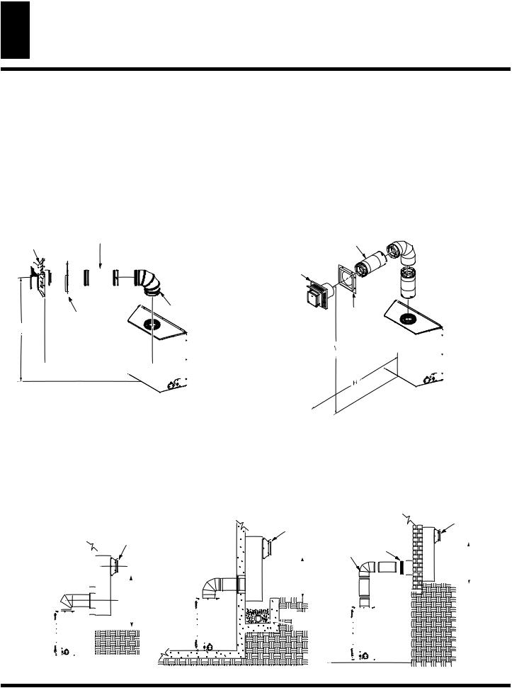
6.Noncombustible Exterior Wall: Position the horizontal vent cap in the center of the 8 ½” round hole and attach to the exterior wall with four wood screws provided. Before attaching theventcaptoexteriorwall,runabeadofnon-hardeningmastic (pliable sealant) around the outside edges to make a seal between it and the outside wall. Note: The four wood screws provided should be replaced with appropriate fasteners for stucco,brick,concrete,orothertypesofsidings.(SeeFigure13).
Combustible Exterior Wall: For vinyl siding, stucco or wood exteriors, a siding standoff may be installed between the vent cap and exterior wall. The siding standoff prevents excessive heat from damaging the siding materials. Siding material must be cut to accommodate standoff. Bolt the vent cap to the standoff.Apply non-hardeningmasticaroundoutsideedgeof standoff. Position the standoff/cap assembly in the center of the 10 ¾ square hole and attach to exterior wall with wood screws provided (see Figure 14). The siding standoff must sit flush against the exterior fascia material.
7.Combustible ExteriorWall Only: Fit the outer and inner wall firestop into the wall before connecting horizontal run to vent cap (see Figure 15).
8.Carefully move fireplace, with vent assembly attached, toward wall and insert vent pipe into horizontal termination. The pipe overlap should be a minimum of 1 ¼”.
9.CombustibleExteriorWallOnly:Slidewallfirestopagainst interiorwallsurfaceandattachwithscrewsprovided(seeFigure 16). See Figure 17 for horizontal termination details.
10.Placefireplaceintopositionandshimwithnoncombustiblematerial, if needed. Nail or screw flanges to framing to secure unitinplace.IMPORTANT:Makesurefireplaceislevelbefore securing. If fireplace is not level, it will not work properly.
INNER WALL
FIRESTOP
VINYL
SIDING
STANDOFF
VENT
CAP
HOT

APPLY
MASTIC
TO ALL SIDES
SCREWS
Figure 14 - Installing Siding Standoff
INNER WALL
FIRESTOP
OUTER WALL
FIRESTOP
VENT
CAP


 HOT
HOT


Figure 15 - Installing Outer Wall Firestop
VENT
CAP
SCREWS


 HOT
HOT

INNER WALL
FIRESTOP
PIPE SECTION
Figure 13 - Installing Horizontal Vent Cap (Noncombustible)
VENT CAP
Figure 16 - Installing Inner Wall Firestop
www.desatech.com |
116035-01B |
VENTING INSTALLATION INSTRUCTIONS |
11 |
Installation Planning (Cont.) |
VENTING INSTALLATION
INSTRUCTIONS
Continued
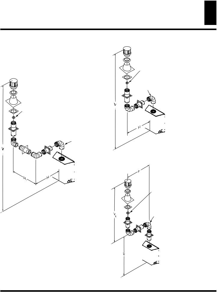
HorizontalTermination Configuration
Figures 19 through 25 show different configurations and alternatives for venting with horizontal terminations. Each figure includes a chart with critical minimum and maximum dimensions which MUST be met. IMPORTANT: Remember that a horizontal run of ventingmusthavea1/4”riseforevery12”ofruntowardthetermination.
Minimum Pipe
Overlap 11/4"
Direct Vent
Pipe
Wall
Firestop
Maintain 1"
Minimum Air
Space Around
Outer Pipe When
Penetrating a Wall
10 3/4" x 10 3/4" Framed Opening
Siding Standoff
Screws
High Wind
Termination
Apply Mastic to Outside Edge of
Standoff
Exterior Wall with Vinyl Siding
Figure 17 -Typical HorizontalTermination Cap Mounting with Additional Siding Standoff Installed
GROUND FLOOR INSTALLATION REAR VENT
Recommended Applications fo Rear Vent Model (V)CD36R:
•Installation using cabinet surrounds
•Through the wall using round or square termination (up to a maximum of 18” of horizontal pipe)
•Corner installation
(Using one 45° elbow and a maximum of 18” of horizontal pipe).
90° Elbow Wall |
Exterior Portion of Wall |
Firestop |
Firestop (Round |
|
Termination Only) |
Horizontal
Round
Termination
Figure 18 - Horizontal Termination Configuration for Round Termination (Model (V)CD36T)
Straight / Adjustable
Pipe 18" Max.
Horizontal
Square
Termination
 TOH
TOH 


Wall
Firestop
Square Termination
Vertical (V) Horizontal (H)
25 1/2 " |
22" max. |
Figure 19 - Horizontal Termination Configuration for Flush Installation (Model (V)CD36R)
Horizontal |
Straight / Adjustable |
|
Square |
||
Pipe 18" Max. |
||
Termination |
45°
Wall Elbow
Firestop
Corner Installation
Vertical (V) |
Horizontal (H) |
25 ½” |
24” |
Figure 20 - Horizontal Termination Configuration for Corner Installation (Model (V)CD36R)
116035-01B |
www.desatech.com |
12 |
VENTING INSTALLATION INSTRUCTIONS |
Installation Planning (Cont.) |
VENTING INSTALLATION INSTRUCTIONS
Continued
GROUND FLOOR INSTALLATION TOP VENT
Recommended Applications for Top Vent Model (V)CD36T:
•Installation using cabinet surrounds
•Through the wall using round or square termination (up to a maximum of 24” of horizontal pipe)
•Corner installation
(Using one 90° elbow and a maximum of 24” of horizontal pipe).
Horizontal |
Straight / Adjustable |
||||||||||
Square |
Pipe 24" Max. |
||||||||||
Termination |
|
|
|
||||||||
|
|
|
|
|
|
|
|
|
|
|
|
|
|
|
|
|
|
|
|
|
|
|
|
|
|
|
|
|
|
|
|
|
|
|
|
|
|
|
|
|
|
|
|
|
|
|
|
|
|
|
|
|
|
|
|
|
|
|
|
|
|
|
|
|
|
|
|
|
|
|
|
|
|
90° |
|
Wall |
Elbow |
|
|
|
V |
Firestop |
|
 H
H 
Corner Installation
Vertical (V) Horizontal (H)
45 ½“ |
32 ½“ |
Figure 21 - Horizontal Termination Configuration for Corner Installation using One 90° Elbow (Model (V)CD36T)
Required |
Vertical (V) |
Vertical (V) |
Vertical Pipe |
45 ½” |
None |
57 ¼” Min. |
1 ft. |
69 ¼” Min. |
2 ft. |
81 ½” Min. |
3 ft. |
94” Min. |
4 ft. |
106” Min. |
5 ft. |
159” Min. |
9 ft. |
|
Not to Exceed |
|
(H) Limits |
Square |
|
Termination |
|
TOH |
|
|
Wall |
|
Firestop |
Allowable
Horizontal (H)
26” Max.
30” Max.
74” Max.
98” Max.
122” Max.
146” Max.
20’ Max.

 90° Elbow
As Required for (V)
 See Chart for Pipe
Section Required
Figure 22 - Horizontal Termination Configuration with Vertical Rise and One 90° Elbow (Model (V)CD36T)
SNORKEL TERMINATION INSTALLATION
Recommended Applications Models (V)CD36R and (V)CD36T:
• |
Installations requiring vertical rise on building exterior. |
• |
Installation using snorkel termination to achieve 1 ft. above grade. |
Snorkel terminati
you must provide proper drainage to prevent water from entering snorkel (see Figure 23). Do not back fill around snorkel termination.
|
|
|
Snorkel |
Snorkel |
Snorkel |
|
Termination |
|
|
||
Termination |
Wall |
|
|
Termination |
|
||
|
|
||
|
90° Elbow |
Firestop |
12" |
|
12" |
|
Minimum |
|
|
|
|
|
Minimum |
|
|
12" Minimum
 Adequate
  Drainage
Figure 23 - SnorkelTermination Configurations for Below Ground Installation
www.desatech.com |
116035-01B |

VENTING INSTALLATION INSTRUCTIONS |
13 |
Installation Planning (Cont.) |
HORIZONTAL SYSTEM INSTALLATION USING TWO 90° ELBOWS
The following configurations show the minimum vertical rise requirements for a horizontal system using two 90° elbows.
Venting with Two 90° Elbows
|
Horizontal (H1) + |
90° Elbow |
Vertical (V) |
|
|
Horizontal (H2) |
|
|
8' min. |
9' max. |
|
9' min. |
11' max. |
|
10' min. |
13' max. |
|
12' min. |
17' max. |
|
14' min. |
20' max. |
|
Figure 24 - HorizontalTermination Configuration for Venting usingTwo 90° Elbows (Model (V)CD36T)
Venting with Three 90° Elbows
Vertical (V) |
|
Horizontal (H1) + |
Horizontal (H1) |
Horizontal (H2) |
|
5' min. |
2' max. |
6' max. |
6' min. |
3' max. |
8' max. |
7' min. |
4' max. |
10' max. |
8' min. |
5' max. |
12' max. |
12' min. |
8' max. |
20' max. |
20' max. |
8' max. |
20' max. |
90° Elbow
 TOH
TOH 


Figure 25 - HorizontalTermination Configuration for Venting usingThree 90° Elbows (Model (V)CD36T)
116035-01B |
www.desatech.com |
14 |
VENTING INSTALLATION INSTRUCTIONS |
Installation for VerticalTerminations |
VENTING INSTALLATION INSTRUCTIONS
Continued
Note: Vertical restrictor must be installed in all vertical installations.
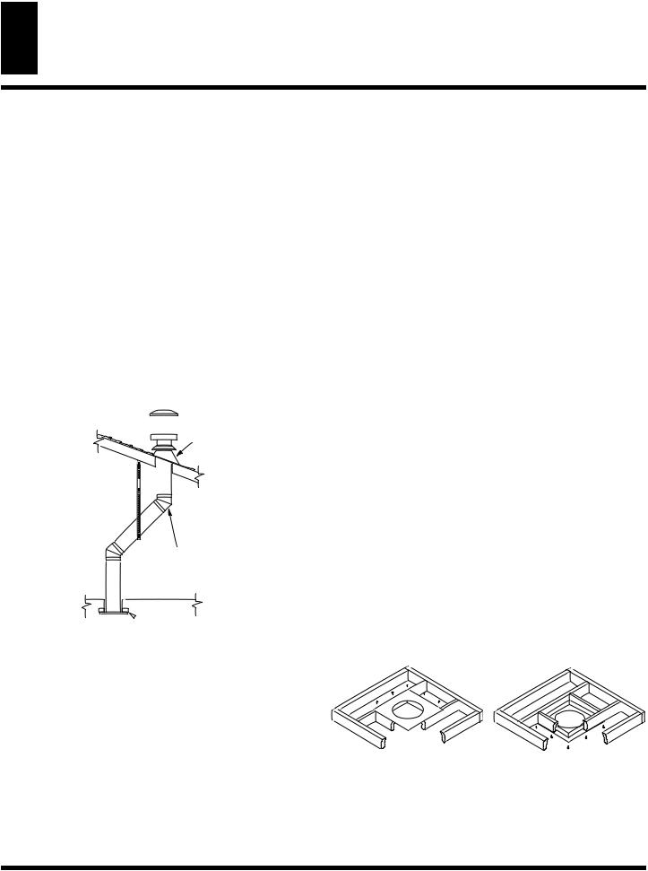
1.Determine the route your vertical venting will take. If ceiling Joists, roof rafters, or other framing will obstruct the venting system,consideranoffset(seeFigure26)toavoidcuttingload bearing members. NOTE: Pay special attention to these installation instructions for required clearances (air space) to combustibles when passing through ceilings, walls roofs, enclosures, attic rafters, etc. Do not pack air spaces with insulation. Also note maximum horizontal offset limitations.
2.Set fireplace in desired location. Drop a plumb line down from the ceiling to the position of the fireplace exit flue. Mark the center point where the vent will penetrate the ceiling. Drill a small locating hole at this point.
Drop a plumb line from the inside of the roof to the locating hole in the ceiling. Mark the center point where the vent will penetrate the roof. Drill a small locating hole at this point.
Roof Flashing
Wall Strap

 45° Elbow

 Ceiling Firestop
Figure 26 - Offset with Wall Strap and 45° Elbows
2.Assemble the desired lengths of pipe and elbows necessary to reach from the fireplace flue up through the firestop. Be sure all pipe and elbow connections are fully twist-locked (see Figure 11, page 9).
3.Cut a hole in the roof using the locating hole as a center point. (Coveranyexposedopenventpipesbeforecuttingholeinroof.) The 10 ¾” x 10 ¾” hole must be measured on the horizontal; actuallengthmaybelargerdependiongonthepitchoftheroof. Theremustbea1”clearancefromtheventpipetocombustible materials. Frame the opening as shown in Figure 12, page 9.
4.Connect a section of pipe and extend up through the hole.
Note: If an offset is needed to avoid obstructions, you must support the vent pipe every 3 feet. Use wall straps for this purpose (see Figure 26). Whenever possible, use 45º elbows instead of 90º elbows. The 45º elbow offers less restriction to the flow of the flue gases and intake air.
5.Place the flashing over the pipe section(s) extending through the roof. Secure the base of the flashing to the roof and framing with roofing nails. Be sure roofing material overlaps the top edge of the flashing as shown in Figure 26. There must be a 1” clearnace from the vent pipe to combustible materials
6.Continue to add pipe section until the height of the vent cap meets the minimum building code requirements described in Figure 10 on page 7. Note: You must increase vent height for steep roof pitches. Nearby trees, adjoining rooflines, steep pitched roofs, and other similar factors may cause poor draft ordown-draftinginhighwinds.Increasingtheventheightmay solve this problem.
7.Twist-lock the vent cap onto the kast section of vent pipe.
Note: If the vent pipe passes through any occupied areas above the first floor, including storage spaces and closets, you must enclose pipe. You may frame and sheetrock the enclosure with standard construction material. Make sure and meet the minimum allowable clearancestocombustibles.Donotfillanyoftherequiredairspaces with insulation.
If area above is a room, install |
If the area above is not a room, install |
firestop above framed hole. |
firestop below framed hole. |
Flat Ceiling Installation
1. Cuta10¾”squareholeintheceilingusingthelocatingholeas
a center point.The opening should be framed to 10 ¾” x 10 ¾” (273 mm x 273 mm) inside dimensions, as shown in Figure 12
on page 9 using framing lumber the same size as the ceiling joists. If the area above the ceiling is an insulated ceiling or a room,nailfirestopfromthetopside.Thispreventslooseinsula-
tion from falling into the required clearance space. Otherwise, Figure 27 - Installing Firestop install firestop below the framed hole. The firestop should be
installed with no less than three nails per side (see Figure 27).
www.desatech.com |
116035-01B |
VENTING INSTALLATION INSTRUCTIONS
Continued
VerticalTermination Configurations
Figures 28 through31 showfourdifferentconfigurationsforvertical termination.
|
Venting with Three 90° Elbows |
||
Note: Install |
Vertical (V) |
Horizontal (H1) + |
|
|
Horizontal (H2) |
||
restrictor ring |
|
||
into inner pipe |
8' min. |
5' max. |
|
section prior to |
10' min. |
8' max. |
|
attaching vent |
12' min. |
11' max. |
|
termination cap. |
|||
14' min. |
14' max. |
||
|
16' min. |
17' max. |
|
|
18' min. |
20' max. |
|
|
40' max. |
20' max. |
|
90° Elbow
VENTING INSTALLATION INSTRUCTIONS |
15 |
Installation for VerticalTermination (Cont.) |
Note: Install restrictor ring into inner pipe section prior to attaching vent termination cap.
|
Venting with Two 90° Elbows |
||
|
Vertical (V) |
Horizontal H |
|
90° Elbow |
8' min. |
6' max. |
|
9' min. |
8' max. |
||
|
|||
|
10' min. |
10' max. |
|
|
12' min. |
14' max. |
|
|
14' min. |
18' max. |
|
|
40' max. |
20' max. |
|
Figure 28 - Vertical Venting Configuration usingThree 90° Elbows (Model (V)CD36T with Vertical Round High WindTermination)
Figure 29 - Vertical Venting Configuration UsingTwo 90° Elbows (Model (V)CD36T with Vertical Round High WindTermination)
Note: Install restrictor ring into inner pipe section prior to attaching vent  termination cap.
90° Elbow
Venting with Two 90° Elbows
Vertical (V1) |
Horizontal (H) |
8' min. |
9' max. |
9' min. |
11' max. |
10' min. |
13' max. |
12' min. |
17' max. |
14' min. |
20' max. |
Note: Vertical (V1) + Vertical (V2) = 40' max. Max.Horizontal Above 14' Vertical = 20'
Figure 30 - Vertical Venting Configuration UsingTwo 90° Elbows (Model (V)CD36T with Vertical Round High WindTermination)
116035-01B |
www.desatech.com |
 Loading...