


 Loading...
Desa VP324E, P325EB, P324E, VP325EB, P325E User Manual
...B-VENT DECORATIVE GAS FIREPLACE
TM OWNER’S OPERATION AND
INSTALLATION MANUAL


 For more


 visit www.

 .com
.com


MODELS P324E, VP324E, P325E(B) AND VP325E(B)
NATURAL GAS
WARNING: If the information in these instructions is not followed exactly, a fire or explosion may result causing property damage, personal injury or death.
FOR YOUR SAFETY
—Do not store or use gasoline or any other flammable vapors or liquids in the vicinity of this or any other appliance.
—WHAT TO DO IF YOU SMELL GAS :
•Do not try to light any appliance.
•Do not touch any electrical switch;
•Do not use any phone in your building.
•Immediately call your gas supplier from a neighbor’s phone. Follow the gas supplier’s instructions.
•If you cannot reach your gas supplier, call the fire department.
—Installation and service must be performed by a qualified installer, service agency, or the gas supplier.
SAVE THIS BOOK
This book is valuable. In addition to instructing you on how to install and maintain your appliance, it also contains information that will enable you to obtain replacement parts or optional accessory items when needed. Keep it with your other important papers.
WARNING: Improper installation, adjustment, alteration, service or maintenance can cause injury or property damage. Refer to this manual. For assistance or additional information consult a qualified installer, service agency, or the gas supplier.
NOT FOR USE WITH SOLID FUEL
CHECK LOCAL CODES PRIOR TO
INSTALLATION
This appliance may be installed in an aftermarket* manufactured (mobile) home, where not prohibited by state or local codes.
This appliance is only for use with the type of gas indicated on the rating plate.
This appliance is not convertible for use with other gases, unless a certified kit is used.
*Aftermarket: Completion of sale, not for purpose of resale, from the manufacturer.


 Save this
 for
for


 .
.


2 |
TABLE OF CONTENTS |
SAFETY INFORMATION |
|
|
|
TABLE OF CONTENTS |
|
SAFETY INFORMATION ............................................................ |
2 |
UNPACKING ............................................................................... |
3 |
INTRODUCTION......................................................................... |
4 |
PRODUCT SPECIFICATIONS .................................................... |
5 |
SELECTING LOCATION ............................................................. |
5 |
PRE-INSTALLATION PREPARATION ........................................ |
6 |
VENTING INSTALLATION .......................................................... |
8 |
INSTALLATION ......................................................................... |
10 |
OPERATING FIREPLACE ........................................................ |
15 |
INSPECTING BURNERS .......................................................... |
16 |
CLEANING AND MAINTENANCE |
............................................ |
17 |
SERVICE HINTS ....................................................................... |
|
18 |
TECHNICAL SERVICE ............................................................. |
|
18 |
WIRING DIAGRAM ................................................................... |
|
18 |
REPLACEMENT PARTS .......................................................... |
|
18 |
TROUBLESHOOTING .............................................................. |
|
19 |
ACCESSORIES ........................................................................ |
|
21 |
ILLUSTRATED PARTS BREAKDOWN .......AND PARTS LIST |
22 |
|
WARRANTY INFORMATION ....................................... |
Back Page |
|
SAFETY INFORMATION
 WARNINGS
IMPORTANT: Read this owner’s manual carefully and completelybeforetryingtoassemble,operate,orservice this fireplace. Improper use of this fireplace can cause serious injury or death from burns, fire, explosions, electrical shock, and carbon monoxide poisoning.
 DANGER: Carbon monoxide poisoning may lead to death!
This fireplace is a vented product. This fireplace will not produce any gas leakage into your home if properly installed. This fireplace must be properly installed by a qualified service person. If this unit is not properly installed by a qualified service person, gas leakage can occur.
Carbon Monoxide Poisoning: Early signs of carbon monoxide poisoning resemble the flu, with headaches, dizziness, or nausea. If you have these signs, the fireplace may not have been installed properly. Get fresh air at once! Have fireplace inspected and serviced by a qualified service person. Some people are more affected by carbon monoxide than others. These include pregnant women, people with heart or lung disease or anemia, those under the influence of alcohol, and those at high altitudes.
Propane/LP gas and natural gas are both odorless. An odor-making agent is added to each of these gases. The odor helps you detect a gas leak. However, the odor added to these gases can fade. Gas may be present even though no odor exists.
Make certain you read and understand all warnings. Keep this manual for reference. It is your guide to safe and proper operation of this fireplace.
 WARNING: Any change to this fireplace or its controls can be dangerous.
1.This appliance is only for use with the type of gas indicated on the rating plate. This appliance is not convertible for use with other gases unless a certified kit is used.
2.For propane/LP fireplace, do not place propane/LP supply tank(s) inside any structure. Locate propane/LP supply tank(s) outdoors. To prevent performance problems, do not use propane/LP fuel tank of less than 100 lbs. capacity.
3.If you smell gas
•shut off gas supply
•do not try to light any appliance
•do not touch any electrical switch; do not use any phone in your building
•immediately call your gas supplier from a neighbor’s phone. Follow the gas supplier's instructions
•if you cannot reach you gas supplier, call the fire department.
4.Never install the fireplace
•in a recreational vehicle
•where curtains, furniture, clothing, or other flammable objects are less than 42" from the front, top, or sides of the fireplace
•in high traffic areas
•in windy or drafty areas
5.This fireplace reaches high temperatures. Keep children and adults away from hot surfaces to avoid burns or clothing ignition. Fireplace will remain hot for a time after shutdown. Allow surfaces to cool before touching.
6.Carefully supervise young children when they are in the room with fireplace.
7.A hearth extension is not required with this appliance. If one is installed, it is for aesthetic purposes only and does not have to meet the standard requirements.


 For more


 visit www.

 .com
.com


108794

SAFETY INFORMATION UNPACKING 3
SAFETY INFORMATION
Continued
8.Turn fireplace off and let cool before servicing or repairing. Only a qualified service person should install, service, or repair this fireplace. Have fireplace inspected annually by a qualified service person.
9.You must keep control compartments, burners, and circulating air passages clean. More frequent cleaning may be needed due to excessive lint and dust from carpeting, bedding material, etc. Turn off the gas valve and pilot light before cleaning fireplace.
10.Have venting system inspected annually by a qualified service person. If needed, have venting system cleaned or repaired. See Cleaning and Maintenance, page 17.
11.Keep the area around your fireplace clear of combustible materials, gasoline, and other flammable vapor and liquids. Do not run fireplace where these are used or stored. Do not place items such as clothing or decorations on or around fireplace.
12.Do not use this fireplace to cook food or burn paper or other objects.
13.Do not use any solid fuels (wood, coal, paper, cardboard, etc.) in this fireplace. Use only the gas type indicated on fireplace nameplate.
14.This appliance, when installed, must be electrically grounded in accordance with local codes or, in the absence of local codes, with the National Electrical Code, ANSI/NFPA 70, or the Canadian Electrical Code, CSA C22.1.
15.Do not install fireplace directly on carpeting, vinyl tile, or any combustible material other than wood. The fireplace must set on a metal or wood panel extending the full width and depth of the fireplace.
16.Do not use fireplace if any part has been exposed to or under water. Immediately call a qualified service person to arrange for replacement of the unit.
17.Do not operate fireplace if any log is broken.
18.Do not use a blower insert, heat exchanger insert, or other accessory not approved for use with this fireplace.
UNPACKING
The following items are packed inside the firebox. Remove before positioning firebox into framing.
•Ceramic Log Pack - Shrink-wrapped on cardboard
•Three (3) plastic bags containing lava rock, pan and ember materials
•Rear Log (P325E/VP325E Models Only) - Remove the two plastic quick ties from around the burner and grate
•Grate Stand - Lift off of burner pan
Check all items for any shipping damage. If damaged, promptly inform dealer or distributor where you bought the product.
Safely retain these items for later installation.


 For more information, visit www.desatech.com
108794
INTRODUCTION
4 Before You Begin
INTRODUCTION
These fireplace models are vented gas fireplaces that use an electronic gas control valve and electronic ignition system. P325E/ VP325E models have a 5" B-vent and P324E/VP324E models have a 4" B-vent. A properly sized B-Type venting system and a listed type vent cap are not supplied but are required for proper operation. See venting instructions on pages 8 and 9.
 WARNING: This gas appliance must not be connected to a chimney flue servicing a solid fuel burning appliance.
These models are factory equipped for use with natural gas and must be converted when intended for use with propane/LP gas. Conversion kits PCBE-324 and PCBE-325 may be purchased for simple conversion to propane/LP gas. See Accessories, page 21.
BEFORE YOU BEGIN
Before beginning the installation of your appliance, read these instructions through completely.
This DESA appliance and its approved components are safe when installed according to this installation manual and are operated as recommended by DESA. Unless you use DESA approved components tested for this appliance, YOU MAY CAUSE A FIRE HAZARD!
The DESA warranty will be voided by, and DESA disclaims any responsibility for the following actions :
A)Modification of the appliance or any of the components.
B)Use of any component part not approved by DESA in combination with this appliance.
C)Installation and/or operation in a manner other than instructed in this manual.
D)The burning of anything other than the type of gas approved for use in this gas appliance.
The installation must conform with local codes or, in the absence of local codes, with the current National Fuel Gas Code, ANSI Z223.1 or with the current CAN/CSA B149 Installation Codes.
This appliance complies with ANSI Z21.50-2000 and CSA 2.222000 as Vented Gas Fireplaces and is listed and tested by the Canadian Standards Association to the above test standards.
 WARNING: Installation of this appliance should be done by a qualified service person well trained in the installation of such appliances. You will also need a building permit from your local Building and Safety Commissioner before installing this appliance; otherwise your insurance co. may not cover this appliance.
NOTICE: This appliance is not intended to be used as a primary source of heat.
 CAUTION: Do not connect appliance before pressure testing gas piping. Damage to gas valve may result and an unsafe condition may be caused.
The appliance and it’s individual shutoff valve must be disconnected from the gas supply piping system during any pressure testing of that system at test pressures in excess of 1/2 psig (3.5 kPa).
The appliance must be isolated from the gas supply piping system by closing its individual equipment shutoff valve during any pressure testing of the gas supply piping system at test pressures equal to or less than 1/2 psig (3.5 kPa).
For the purpose of input adjustment two pressure taps (for IN and OUT pressures) are provided on the gas control valve for test gauge connections to the appliance.
GAS RATING - NATURAL
|
P324E, VP324E |
|
P325E(B), VP325E(B) |
Max. Input Rating: |
15,000 Btu/Hr |
|
25,000 Btu/Hr |
Manifold Pressure: |
3.5 in. WC (.87 kPa) |
|
3.5 in. WC (.87 kPa) |
Minimum Supply Pressure: |
4.5 in. WC (1.12 kPa) |
|
4.5 in. WC (1.12 kPa) |
Maximum Supply Pressure: |
10.5 in. WC (2.66 kPa) |
|
10.5 in. WC (2.66 kPa) |
|
|
|
|
Orifice Size: |
# 49 |
|
# 40 |
|
|
|
|
GAS RATING - PROPANE/LP |
|
||
Max. Input Rating: |
15,000 Btu/Hr |
|
25,000 Btu/Hr |
Manifold Pressure: |
10.0 in. WC (2.49 kPa) |
|
10.0 in. WC (2.49 kPa) |
Minimum Supply Pressure: |
11.0 in. WC (2.74 kPa) |
|
11.0 in. WC (2.74 kPa) |
Maximum Supply Pressure: |
13.0 in. WC (3.23 kPa) |
|
13.0 in. WC (3.23 kPa) |
Orifice Size: |
# 56 |
|
# 54 |


 For more


 visit www.

 .com
.com


108794
PRODUCT SPECIFICATIONS |
5 |
SELECTING LOCATION |
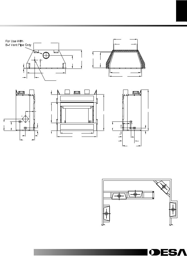
PRODUCT SPECIFICATIONS
|
22 3/8" |
|
|
21 1/2" |
|
|
|
* 20 3/8" |
|
|
7" |
14 |
1/2" |
HEARTH AREA |
|
16 3/4" |
* 13 3/4" |
||
|
|
11 3/4" |
DIMENSIONS |
|
5/8" |
34 1/2" |
|
|
* 27 1/2" |
7" |
|
|
29" |
|
|
Alternate Gas |
|
||
|
|
|
||
|
|
|
* WITH REFRACTORY |
|
|
|
Supply Inlet |
|
|
|
7" |
|
|
|
|
|
8 1/8" |
18 1/4" |
32 1/4" |
|
|
|
36 1/2" |
|
10 1/2" |
|
|
8 1/4" |
|
|
6 7/8" |
|
8 1/4" |
1/2" |
7" |
|
|
|
|
|
2 |
29 1/2" |
|
|
|
|
|
|
8 3/8" |
|
2 1/2" |
5/8" |
2 1/4" |
|||
|
35 3/8" |
7 |
|||||
13 1/4" |
|
|
10 |
5 |
/8" |
|
|
|
|
|
|
|
|||
|
|
|
|
|
16 3/4" |
|
|
Figure 1 - Appliance Dimensions
SELECTING LOCATION
To determine the safest and most efficient location for your appliance, you must take into consideration the following guidelines:
1.The location must allow for proper clearances (see Clearances, page 6).
2.Consider a location where heat output would not be affected by drafts, air conditioning ducts, windows, or doors.
3.A location that avoids the cutting of joists or roof rafters will make installation easier. Figure 2 shows a plan view of a few common locations.
Flush installations are recommended where living space is limited or at a premium, and since the space required to enclose the appliance would be located beyond an outside wall, this would also reduce the cutting of joists, roof rafters, and such. Check local codes for any restrictions.
Internal wall installations provide a discreet option for room separation and can also be ideal as an addition to an existing wall.
CORNER
INTERNAL WALL INSTALLATION
INSTALLATION
FLUSH
FULL INSTALLATION
PROJECTION
INSTALLATION
Projected installations can extend any distance into the room. A Figure 2 - Possible Locations for Installing Appliance projection may be ideal for a new addition on an existing, finished wall.
Corner installations make use of space that may not normally be used and provides a wider and more efficient range for radiant heat transference.


 For more information, visit www.desatech.com
108794

6 |
PRE-INSTALLATION PREPARATION |
Clearances |
|
|
Mantel Clearances and Wall Details |
|
|
PRE-INSTALLATION
PREPARATION
CLEARANCES
Minimum clearances to combustibles are: |
|
|
• |
Top of Spacers ........................................................... |
0" min. |
• |
Back and Sides of Outer Surround ............................ |
0" min. |
• |
Drywall to Sides of Front Face (Nailing Flanges) ... 0" min. |
|
• |
“B” Vent Surfaces ..................................................... |
1" min. |
• |
Ceiling to Opening .................................................. |
42" min. |
• |
Floor .......................................................................... |
0" min. |
• |
Perpendicular Wall ............................................ |
See Figure 6 |
 CAUTION: Do not block required air spaces with insulationoranyothermaterial.Donotobstructeffective opening of appliance with any type of facing material.
2 x 4 Stud
Nailing
Flange
Back
0" Clearance 
Left Side
Surround
0"
Front Face |
Drywall |
|
Figure 3 - Minimum Clearances (Top View)
1" (25mm) Min. 
 Clearance to
"B" Vent’s Outer Pipe
Ceiling
42" (1067mm) Min. Clearance from Opening to Ceiling
0" Clearance |
|
|
|
|
* |
* |
* |
* |
Required Air |
|
|
|
|
Spaces are |
|
|
|
|
Indicated with |
|
|
|
|
an "*". Do Not |
|
|
|
|
Pack with |
|
|
|
|
Insulation or Any |
|
DO NOT BLOCK |
|
Other Material |
|
|
|
|
||
|
OR OBSTRUCT |
|
|
|
|
|
OPENINGS |
|
|
0" Clearance to Wood or
Noncombustible Flooring
MANTEL CLEARANCES AND WALL DETAILS
A combustible mantle shelf maybe installed a maximum 12" (229mm) from the wall. Figures 5 and 6 show the minimum allowable distances from various combustible mantle components in relation to the fireplace opening.
12" |
Combustible |
(229mm) |
Materials |
Header
6" (152mm)
13"
8" Spacer
(Front View) |
3" (76mm) |
|
1 1/2"  (38mm) Max.
Figure 5 - Mantel Clearances - Side View (Cross Section)
TOP VIEW
Outer Surround
Combustible
Material May
Be Used
1 1/2" (38mm) |
SAFE |
|
ZONE |
||
Max. |
3" (76mm) |
|
|
Max. |
|
6" (152mm)  Max.
Max.
9"
|
Perpendicular |
12" |
Wall |
Figure 6 - Side Clearances - Top View (Cross Section)
Figure 4 - Minimum Clearances (Front View)


 For more


 visit www.

 .com
.com


108794
PRE-INSTALLATION PREPARATION
Framing 7
PRE-INSTALLATION
PREPARATION
Continued
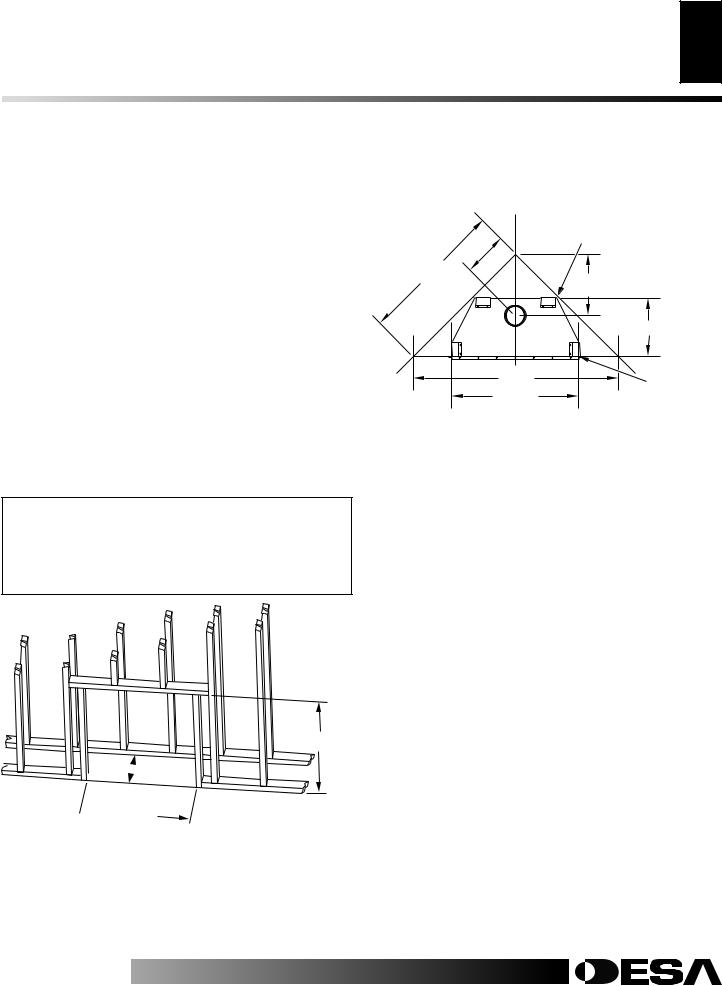
FRAMING
1.Frame appliance enclosure as illustrated in Figures 7 and 8.
Note: If a wall covering is used to line the enclosure, then all measurements must be from the surface of the covering.
2.Place the appliance into the framing and secure it.
Note: If appliance is to be raised above floor level, a platform must be built to support the appliance.
3.Install the supply line to the appliance using a 1/2" NPT black iron gas line terminating 2 5/16" above the bottom of the appliance. The gas line may be installed from either side or from the rear of the appliance (see Figure 16, page 11).
4.Feed flexible gas line through one of three gas line conduit sleeve and repack insulation to cover any openings. Prepare the incoming gas line with teflon tape or pipe joint compound and hook-up incoming gas line to the flexible gas line.
Note: If 1/2" NPT black iron pipe does not mate with fitting at the end of flexible gas line, remove fitting and replace with a 37 degree flare 3/4"-12, 1/2" NPT (female) fitting.
 WARNING:Whenfinishingappliance,donotoverlap combustiblematerialontotheblackfrontface.Brick,tile, or other noncombustible materials may be applied to the face provided that any gap is between the material used and the face is caulked with a noncombustible caulking.
These Dimensions Allow for a 3/4" Clearance at Sides and Back of Fireplace. However, 0" Clearance is Permitted
12"
39 3/8"
16 3/4"
|
16" |
55 5/8" |
3/4" Clearance |
Not Required |
|
34 1/2" |
at Nailing |
|
Flanges |
Figure 8 - Corner Installation Guidelines
36 5/8"
 16 1/8"
 34 3/4"
Figure 7 - Rough Opening for Installing in Wall


 For more information, visit www.desatech.com
108794
VENTING INSTALLATION
8
VENTING INSTALLATION
A B-type venting system must be connected to the appliance for venting to the outside of the building.
The following section is provided as a guide to a standard B-type vent installation.
Standing codes requirements concerning B-type vent installations may vary within your state, province or local codes jurisdiction. Therefore, it is recommended that you check with your local building codes for specific requirements or in absence of local codes, follow Section 7.0 of the current National Fuel Gas Code NFPA No. 54/ANSI Z223.1 and in Canada with CAN/CSA B149 for Category I systems using double wall B-1 vent pipe.
This gas appliance must be vented to the outdoors only and may not be terminated into an attic space or into a chimney flue servicing a solid-fuel burning appliance.
This appliance may be vented through a manufactured chimney system or a masonry chimney using a B-vent adapter or a chimney liner system if all are listed, inspected and approved by local codes and/or building authorities.
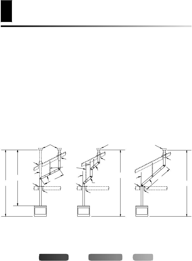
The examples shown in Figure 9 are typical of most B-vent installations and codes practices.
Example 1: Shows the minimum allowable system height and lateral offset for a 60° degree or greater inclination. Code specifies that offsets at 60° degrees or greater are considered horizontal and must follow the 75% percent rule for lateral to total vertical system height. Codes also allows only one offset in the total system when at 60° degrees or greater. The total vertical height in this example represents the minimum height of 8 feet and therefore the allowable lateral is 6 feet when the 75% percent rule applies. If the lateral length must exceed 75% then the system must be sized in accordance with the Category I venting tables.
Example 2: Shows a multiple offset each at 45° degrees of inclination. Multiple offsets are permitted if they do not exceed 60° degrees of inclination. The total lengths of the two offsets are not required to meet the 75% percent allowable rule.
Example 3: Shows a single offset at 45° degrees of inclination and therefore the lateral length at 10 feet of offset does not have to meet the 75% percent rule.
In each case the offsets must be supported and firestops must be positioned wherever the vent must pass through a sub-floor, ceiling joist or an attic overhang. The vent pipe must terminate vertically into a listed type vent cap and extend a sufficient height through an approved roof flashing, roof jack or a roof thimble. At all points the listed clearances must be maintained.
|
|
Listed |
|
|
|
|
|
|
|
Vent Cap |
|
|
Listed |
Listed |
|
|
|
|
|
|
Vent Cap |
||
|
|
|
|
|
Vent Cap |
||
|
|
|
|
|
|
||
|
Maintain |
|
Maintain |
|
|
|
|
|
|
Listed |
|
|
|
Maintain |
|
|
Listed |
|
|
|
|
||
|
|
Clearance |
|
Maintain |
|
Listed |
|
|
Clearance |
|
|
|
|||
|
|
Support Each |
|
Listed |
|
Clearance |
|
|
|
|
|
|
|||
|
|
|
Lateral At |
|
Clearance |
|
|
|
|
|
Least Every |
45° |
|
|
|
|
|
60° |
Six (6) Feet |
12' Min. |
|
|
|
|
|
|
|
|
|
||
|
8' |
|
|
|
45° |
10' |
|
|
6' |
|
|
|
|||
12' Min. |
Position |
|
45° |
Position |
|
12' Min. |
|
|
Position |
|
|||||
|
Firestop |
|
Firestop |
|
Firestop |
|
|
|
|
|
|
|
|
||
|
|
Maintain |
|
Maintain |
|
|
Maintain |
|
|
Listed |
|
Listed |
|
|
Listed |
|
|
Clearance |
|
Clearance |
|
|
Clearance |
EXAMPLE 1 |
EXAMPLE 2 |
EXAMPLE 3 |
Figure 9 - Typical B-Vent Configuration


 For more


 visit www.

 .com
.com


108794
VENTING INSTALLATION |
9 |
Checking for Proper Venting |
VENTING INSTALLATION
Continued
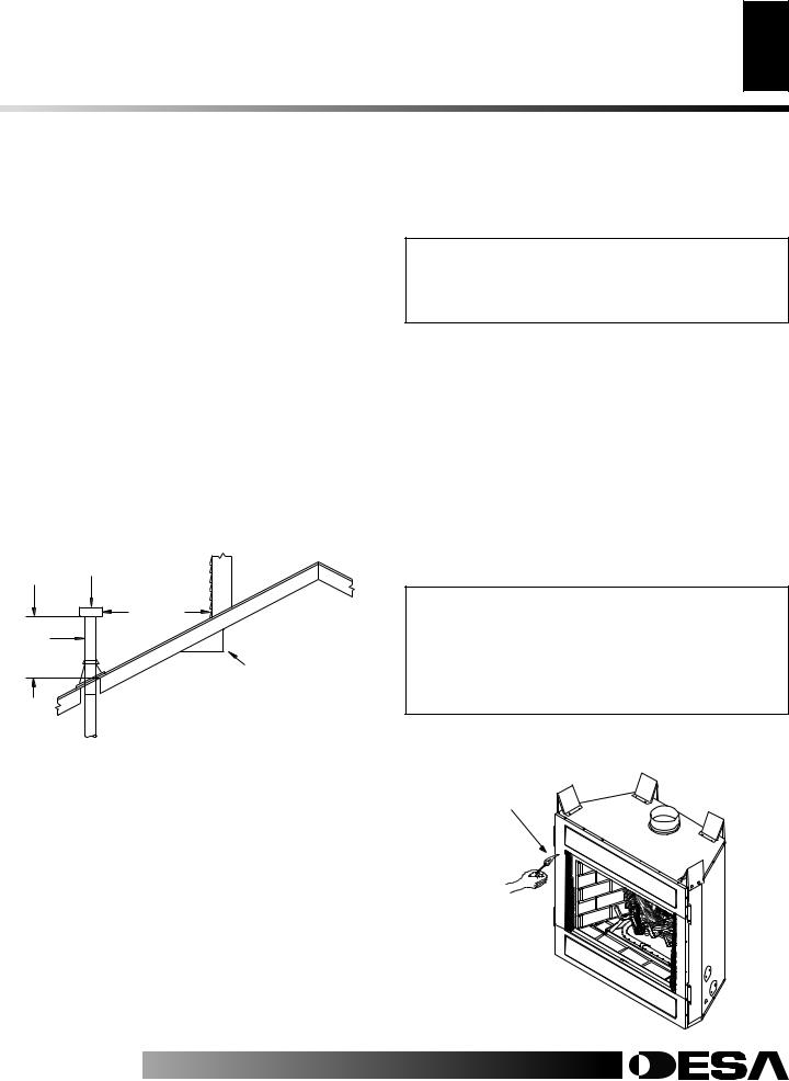
Vent terminations must be located in accordance with height and proximity rules of NFPA No. 54 or CAN/CSA B149. These rules apply to vents at 12 in. diameter or less and require a minimum height in accordance with the roof pitch and a minimum of 8 ft. distance from a vertical wall or obstruction (see Figure 10).
If venting horizontally through a side wall becomes necessary, a listed thimble approved for use with B-type vent must be used. Check with your local codes before venting through a side wall.
Some codes areas allow the use of existing B-type vent systems if the system is at or above the recommended diameter of the flue.
The flue connection must be made using listed B-type connectors and the existing system must be code inspected for damage and proper installation.
It is not recommended that this appliance be common vented with an existing gas burning appliance. However, if it becomes necessary to common vent this appliance, the venting system must be sized and configured in accordance with the common venting guides Appendix G of the current National Fuel Gas Code NFPA No. 54/ ANSI Z223.1 and in Canada with CAN/CSA B149.
Lowest |
Listed |
Discharge |
Vent Cap |
Opening |
|
|
8 Ft. Min. |
Listed Gas |
|
Vent |
x |
|
12 |
|
Roof Pitch x/12 |
|
Listed Clearance |
H (Min) |
|
Height |
|
From Roof |
|
Note: Before connecting this appliance to an existing vent system or a common venting system consult with your local architect, planner, or building official.
 WARNING: This appliance must be properly connected to a system and must not be connected to a chimney flue servicing a separate solid fuel burning appliance.
CHECKING FOR PROPER VENTING
After completing and checking the electrical, gas and vent connections, follow the lighting instructions and allow the main burner to run for approximately 5 minutes. Hold a lighted match or cigarette near the top edge of the fireplace opening and play it along the entire length of the opening (see Figure 11). Proper venting should tend to draw the flame or smoke into the appliance. Improper venting or escaping of spillage of burned gas, is indicated when the match flickers or goes out. Smoke from a cigarette will also tend to disperse away from the appliance.
If the appliance is found to be improperly venting, shut it off and notify your installer or a qualified service agency to inspect the venting system.
NOTICE: This appliance is equipped with a vent safety shutoff switch which will shut down the appliance in the case of a venting problem. Do not bypass the vent safety switch. If the appliance should shut down, contact a qualified installer, service agency, or your gas supplier to have the vent inspected before operating.
|
H (Min.) |
|
Roof Pitch |
Ft. |
m |
|
|
|
Flat to 6/12 |
1.0 |
0.30 |
6/12 to 7/12 |
1.25 |
0.38 |
Over 7/12 to 8/12 |
1.5 |
0.46 |
Over 8/12 to 9/12 |
2.0 |
0.61 |
Over 9/12 to 10/12 |
2.5 |
0.76 |
Over 10/12 to 11/12 |
3.25 |
0.99 |
Over 11/12 to 12/12 |
4.0 |
1.22 |
Over 12/12 to 14/12 |
5.0 |
1.52 |
Over 14/12 to 16/12 |
6.0 |
1.83 |
Over 16/12 to 18/12 |
7.0 |
2.13 |
Over 18/12 to 20/12 |
7.5 |
2.27 |
Over 20/12 to 21/12 |
8.0 |
2.44 |
|
|
|
Figure 10 - B-Vent Terminations
Check this area along the entire top edge of the fireplace opening. Smoke or flame should be drawn into the appliance opening.
Figure 11 - Checking for Spillage


 For more information, visit www.desatech.com
108794
Loading...