


Desa Hwi3000a, Mgh3000ga, Mgh3000a, Mgh4000d, Mgh4000di User Manual
...R
PORTABLE GASOLINE
GENERATORS
OWNER’S OPERATION AND INSTALLATION MANUAL
Generator Models: HWI3000A, MGH3000GA, MGH3000A, MGH4000D, MGH4000DI, MGH5000E,
MGH5000EI, MGH5000EIE, and MGH6500AIE
IMPORTANT: Read and understand this manual before operating or servicing generator. Improper use of generator can cause serious injury. Keep this manual for future reference.

R
PORTABLE GASOLINE GENERATORS
SAFETY
INFORMATION
 WARNINGS
IMPORTANT: Read this owner’s manual and the engine owner’s manualcarefully.Becomefamiliar with this generator before trying to operate or service it. Know its uses, limitations, and any hazards involved. Improper use of generator can cause severe injury or death from explosion, fire, burns, electrical shock, or carbon monoxide poisoning.
 DANGER: Carbon monoxide poisoning may lead to death!
Engine exhaust contains poisonous carbon monoxidegas.Overexposurewillcauseloss ofconsciousnessandwillleadtodeath.Use only in well-vented areas. Make sure area has plenty of free-moving, fresh, outside air. Never run generator in an enclosed or confined area. Never run generator inside occupied building.
Carbon Monoxide Poisoning: Early signs of carbon monoxide poisoning resemble the flu, with headaches, dizziness, and nausea. If you have these signs, get fresh air at once! Some people are more affectedbycarbonmonoxidethanothers. These include pregnant women, persons withheartorlungdiseaseoranemia,those undertheinfluenceofalcohol,andthoseat highaltitudes.Makecertainyoureadand understandallwarnings.Keepthismanual for reference. It is your guide to safe and proper operation of this generator.
Safetyinformationappearsthroughoutthese instructions. Pay close attention to them. Belowaredefinitionsforthesafetyinformation listed throughout this manual.
DANGER: indicatesahazardwhichwillcause severe personal injury, death, or substantial property damage if you ignore warning.
WARNING: indicates a hazard which can causeseverepersonalinjury,death,orsubstantial property damage if you ignore warning.
CAUTION: indicatesahazardwhichwill or can cause minor personal injury or property damage if you ignore warning.
1.Gasoline presents a hazard of fire or explosion. Gasoline is flammable. Its vapor is explosive.
•Keep fuel out of children’s reach.
•Refuel generator in a well-vented area. Do not fill fuel tank in the dark. Do not refuel while engine is running. Unhook all electrical loads and shut off engine before refueling.
•Do not overfill fuel tank. Always allow room for fuel to expand. If you overfill tank, fuel can overflow onto hot generator. This can cause fire or explosion. After refueling, tightly close fuel tank cap.
•Do not spill fuel. Fuel or fuel vapor may ignite. If fuel spills, make sure area is dry before starting engine.
•Never smoke in refueling area. Never allow open flames or sparks in area.
•Store fuel in approved container. Store fuel in a well-vented area free of open flames or sparks.
2.Guard against fire hazard. Keep opera- tionareawell-vented.Keepgeneratorat least three feet away from any object. Do not place flammable objects near generator.
•Do not use generator where flammable vapors are present. Some vapors are heavier than air. These vapors settle in low-lying places.
•Do not use generator in enclosed spaces. This includes motor home or RV generator compartments.
3.Guard against electric shock. Generator produceshighvoltage.Thishighvoltage cancausesevereelectricshock.Onlyresponsible adults should use generator.
•Properly ground generator before starting.
•Never let anyone operate or service generator without proper instructions.
•Avoid contact with live terminals or bare wires.
•Do not use generator outdoors in rain or snow.
•Do not use generator near standing water or snow.
•Do not use if generator is wet or damp.
•Do not use generator in highly conductive areas. These areas include metal decking and steelwork.
•Only use grounded extension cords.
•Do not use any worn or damaged electric cords. Electric shock or damage to generator may result.
•Do not wear damp clothing or wet shoes when using generator.
4.Guard against burns. Hot engine parts cancausesevereinjury.Usecautionand remain alert when using generator.
•Keepchildrenandanimalsawayfrom generator while it is running or hot.
•Keep all covers and shields in place. Keep them tightly secured.
•The muffler becomes very hot during operation. The muffler remains hot for a while after shutdown. Do not touch muffler while it is hot. Do not let muffler touch anything flammable. Let engine cool before transporting or storing.
5.Have standby installation to home or building performed by a licensed electrician. Do not let anyone else wire into a utility circuit. Personal injury, equipment damage, or damage to home could occur.
6.Never connect generator to any existing electrical circuits. The generator output will back-feed into the utility power line. This may electrocute a power company line repair person. Also, if generator is powering electrical circuits, the chance of an electrical fire exists.
7.Battery gives off explosive gases. Keep sparks, flames, and cigarettes away. Do not remove or install battery cables when engine is cranking or running. Only service or use battery in a wellvented area.
8.Battery contains sulfuric acid. Battery acid is poisonous if swallowed. Contact with skin or eyes may cause severe burns. Do not tilt generator with battery installed. Tilting could cause battery acid to spill. Wear protective clothing and face shield when servicing. Keep out of children’s reach.
2 |
118683 |

OWNER’S MANUAL
SAFETY
INFORMATION
Continued
9.Onlyaqualifiedelectricalserviceperson should service and repair generator.
•Generator produces high voltage. Use extreme caution when working on electrical parts.
•Always remove spark plug wire from spark plug before servicing.This will prevent accidental starting.
•Whenworkingongenerator,avoidhot muffler,exhaustmanifold,andengine parts. Severe burns may occur.
•Do not work on generator when tired.
•Use only factory approved replacement parts.
10.Store generator in a well-vented area. Make sure fuel tank is empty. Never store with fuel in tank. Vapors may reach an open flame or spark. Fire or explosion may result.
11.Never operate generator
•if engine speed changes greatly
•if engine misfires often
•if powered items overheat
•if electrical output drops
•if it is sparking
•if it produces smoke or flames
•if it vibrates at high levels
•if it has a damaged receptacle
12.Keep generator and nearby areas clean.
•Keep generator free of oil, mud, and other foreign matter.
•Remove anything that creates slippery areas around generator.
•Remove oily rags and other items that create fire hazards.
•Keep a fire extinguisher nearby. Make sure it is rated ABC by the NFPA. They are good for all uses. Consult your local fire department.
•Keep fire extinguisher well maintained. Be familiar with its use.
13.Know how to stop engine quickly. Know how to use all controls.
14.Prolonged exposure to loud noise can cause hearing loss.
•When working around generator, wear approved hearing protection.
•Remember neighbors when using generator.
PRODUCT IDENTIFICATION
Gas Cap/Fuel Gauge
Control
Panel
120 Volt
Receptacle
120 Volt
Receptacle (GFCI)
120 Volt
Receptacle (Duplex)
Full Power
Selector Switch
120  VOLTS
VOLTS
R |
|
|
|
|
ESET |
|
|
|
|
TEST |
|
|
|
|
FULL |
POWER |
|
|
|
120 |
|
|
|
|
|
|
|
|
|
ONLY |
|
|
|
|
|
|
120 |
|
|
|
|
240V |
120/240 |
|
|
|
|
|
|
ENM |
|
VOLTS |
|
|
00000 |
|
|
|
|
HOURS005 |
|
RESET |
Provision for |
|
|
1/10 |
|
||
|
|
|
RESET |
|
 Auto-Idle Switch
Run Lamp
Hour Meter |
|
120/240 Volt |
Roll Cage |
|
|
Receptacle |
|
Circuit |
|
Breaker |
|
|
Gas Tank |
Choke
Lever
Fuel
Valve
Lever
|
|
Ground |
Starter Grip |
|
Lug |
|
Alternator |
|
|
|
|
Engine |
Engine ON/ |
|
|
|
|
|
OFF Switch |
Oil Dipstick |
Figure 1 - Portable Generator (Model MGH4000D Shown)
118683 |
3 |

R
PORTABLE GASOLINE GENERATORS
GENERAL INFORMATION
Master portable generators are rugged and compact. These generators use brushless alternatorsfordependable,trouble-freeser- vice. Honda gasoline engines provide long life under heavy use. Honda engines have overheadvalves(OHV).Thisprovideshigh performance with lower fuel consumption. These engines are governed to maintain enginespeedof3600RPMunderload.3600 RPM engine speed provides 120/240V, 60 Hz power.
Additional Features
•Circuit breaker protection
•Spark-arresting muffler
•Large fuel tank
•Oil alert system
•Electric starter (models MGH5000EIE and MGH6500AIE)
•15-Amp ground fault circuit interrupter (GFCI) receptacle (Except HWI3000A Model)
UNPACKING
1.Remove generator from carton.
2.Remove any protective packaging applied to generator for shipment.
3.Checkforlooseormissingparts.Check for shipping damage. If any parts are missing or damaged, promptly inform dealer where you bought generator.
4.Battery cables are supplied for models MGH5000EIE and MGH6500AIE only.These cables are in a separate bag inside generator carton. You must installthesecablestoengine.SeeBattery, page 8 for installation instructions.
VENTILATION
 DANGER: Use only in wellvented areas. Make sure area has plenty of free-moving, fresh, outside air. Never run generator in an enclosed or confined area. Never run generator inside occupied building. Engine exhaust contains poisonous carbon monoxidegas.Overexposurewill causelossofconsciousnessand will lead to death.
Thisgeneratorneedscoolingairtorunproperly. Never block free-flowing, cooling air togenerator.Overheatingwilloccurwithout cooling air. This will damage the generator. Keepgeneratoratleastthreefeetawayfrom any object.
DUST, DIRT, RAIN, AND SNOW
 WARNING:Donotusegeneratoroutdoorsinrainorsnow.Donot usegeneratornearstandingwater orsnow.Donotuseifgeneratoris wetordamp.Operating generator in these conditions increases the riskofelectrocution.Severeinjury or death can occur.
Do not use generator in extremely dusty or dirtyconditions.Thiswillseverelyaffectits life.Keepgeneratorclean.Donotallowdust, dirt, rain, or snow to collect on it. Protect generator from outdoor elements.
HIGH AND LOW TEMPERATURE OPERATION
Air temperature affects generator output. Outputdrops1%foreach10°temperaturerise above60°F.Verylowtemperaturesmaymake the engine hard to start. See engine owner’s manual for more information.
4 |
118683 |

OWNER’S MANUAL
SPECIFICATIONS
|
|
|
|
|
MGH5000E |
|
|
|
|
|
MGH4000D |
MGH5000EI |
|
MODEL |
HWI3000A |
MGH3000GA |
MGH3000A |
MGH4000DI |
MGH5000EIE |
MGH6500AIE |
Electrical |
|
|
|
|
|
|
Rated Wattage |
2500 |
2500 |
2500 |
4000 |
5000 |
6500 |
Rated Amperage |
|
|
|
|
|
|
120 V |
20.8 |
20.8 |
20.8 |
33.3 |
41.7 |
57 |
240 V |
–– |
–– |
–– |
16.7 |
20.8 |
28.3 |
Receptacle |
|
|
|
|
|
|
120-V Duplex |
–– |
–– |
–– |
Yes |
Yes |
Yes |
120-V, 20-A Duplex |
Yes |
–– |
–– |
–– |
–– |
–– |
120-V, 15-A GFCI |
No |
Yes |
Yes |
Yes |
Yes |
Yes |
120-V Twist-Lock |
No |
No |
No |
30 Amp |
30 Amp |
30 Amp |
120/240-V Twist-Lock |
No |
No |
No |
20 Amp |
20 Amp |
30 Amp |
120-V Full-Power Switch |
No |
No |
No |
Yes |
Yes |
No |
120/240-V, 50-A |
No |
No |
No |
No |
No |
No |
General |
|
|
|
|
|
|
Honda Engine H.P. |
5.5 |
5.5 |
5.5 |
8 |
9 |
13 |
Honda Model |
GX160K1VX |
GX160K1VX |
GX160K1VX |
GX240K1VA |
GX270VA |
GX390K1VXE |
Fuel Type |
Gasoline |
Gasoline |
Gasoline |
Gasoline |
Gasoline |
Gasoline |
Fuel Tank Capacity |
3.9 qt. |
3.9 qt. |
3.9 qt. |
5 gal. |
8 gal. |
8 gal. |
Oil Alert System |
Yes |
Yes |
Yes |
Yes |
Yes |
Yes |
Start Method |
Recoil |
Recoil |
Recoil |
Recoil |
Recoil/Elec. |
Electric |
Weight (pounds) |
85.5 |
85.5 |
85.5 |
139 |
173 |
247 |
* Single-phase, 1.0 power factor
Note: Ratings apply to SAE standard conditions. Reduce ratings 3 1/2% for each1000feetabovesealeveland1%for each 10° Fahrenheit rise above 60°F.
118683 |
5 |
R
PORTABLE GASOLINE GENERATORS
GENERATOR
FEATURES
OIL ALERT SYSTEM
Theoilalertsystemprotectstheenginefrom low oil damage. This system automatically shuts down the engine and prevents engine restarting if the oil level falls too low.
Note:Whenthishappens,theengineswitch remains in the ON position. The oil alert system is wired into the ON/OFF Switch.
If this system shuts down the engine, the engine will not start until you add oil. Add oil to engine (see Engine Oil, page 7).
Note: Operate generator on a level surface. If not level, the oil may flow away from the oil level sensing device. This will cause the oil alert system to shut down engine.
See engine owner’s manual for more information.
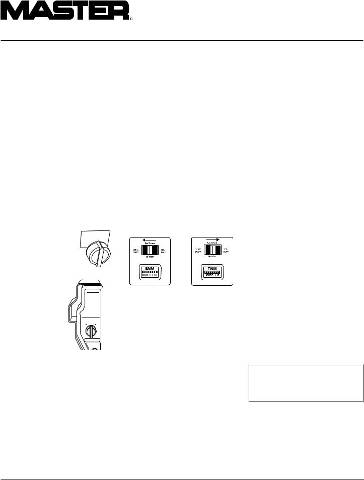
Models HWI3000A, |
ENGINE SW |
MGH3000GA, MGH3000A, |
ON |
MGH4000D, MGH4000DI, |
OFF |
|
|
MGH5000E, and |
|
MGH5000EI |
|
FULL POWER SELECTOR SWITCH
All models except HWI3000A, MGH3000GA, MGH3000A and MGH6500AIE have a full power selector switch on the control panel. The switch has two positions: 120 VOLT ONLY, and 120/240 VOLT.
120 VOLT ONLY: This position sends full power to the 120V receptacles only. 240V power is not available. Use this position when powering 120V items only.
120/240VOLT:Thispositionsendsfullpower to the 120/240V receptacle. It also powers the 120V receptacles at reduced wattage capacity.
IMPORTANT: Do not move the full power selector switch while powering electrical items.Unplugallitemsbeforemovingswitch. Failure to do so can damage switch. Models HWI3000A,MGH3000GA,MGH3000A,and MGH6500AIEdonothavethisswitch.These models provide full power to all receptacles.
HONDA
Models
MGH5000EIE and
MGH6500AIE
ON
OFF  START
START
ENGINE SW
CIRCUIT
BREAKER
Figure 2 - Engine Switch Location
120 VOLT ONLY |
120/240 VOLT |
Position |
Position |
Figure 3 - Full Power Selector Switch
AUTO-IDLE SYSTEM
TheAuto-IdleSystemallowstheenginetoidle down or run at a slower speed when the generator is not being used to supply power. The Auto-idlesystemcanbeturnedONorOFFby arockerswitchonthecontrolpanel.Whenthe switch is in the OFF position, the engine runs at full speed all of the time. When the switch is in the ON position, the engine slows down toidlespeeduntilanelectricalloadisapplied. When a load is applied to the generator (an electricalitemispluggedinandturnedon)the engine speeds up to the preset speed required to produce the correct voltage.
IMPORTANT: A minimum current load of 1 Amp is required to disengage the auto idle solenoid and cause the engine to come up to speed for correct voltage. Powering items at reduced engine speed will damage generator and powered items.
ELECTRIC START
(Models MGH5000EIE and MGH6500AIE)
Models MGH5000EIE and MGH6500AIE have electric starters. A battery is not suppliedwithgenerator.Youmustprovidea12volt, 32-amp-hour battery. For more battery information, see Battery, page 8.
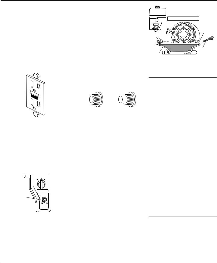
GROUND FAULT CIRCUIT INTERRUPTER RECEPTACLE
Allmodels(ExceptHWI3000A)havea120volt ground fault circuit interrupter (GFCI) receptacle. The GFCI receptacle is on the control panel or top cover of alternator (models MGH3000GA and MGH3000A only). The GFCI protects you against hazardous electrical shock caused when your body becomes a path through which electricity travels to reach ground. This could happen when you touch an appliance or cord that is ‘live’through faulty mechanism, damp or worn insulation, etc.
When protected by the GFCI, you may still feel a shock, but the GFCI should cut it off quickly. A person in normal health should notreceiveseriousinjury.Note:Infantsand very small children may still be affected.
Test Procedure
Check the GFCI receptacle every month. This insures it is working right.
1.Push black TEST button. Red RESET button should pop out. This should trip GFCI, resulting in no electrical power at receptacle. Verify this by plugging test lamp with good bulb into receptacle. If lamp does not work, GFCI receptacle is good.
 WARNING: If RESET button does not pop out, do not use the GFCI receptacle.Contact a qualified electrician for repairs.
6 |
118683 |
OWNER’S MANUAL
GENERATOR
FEATURES
Continued
2.If the GFCI receptacle tests okay, restore power by pushing the RESET button back in. The test lamp should work at this time. IMPORTANT:You must press the RESET button firmly and fully. It should lock into place. If the GFCI does not lock into place, do not use receptacle. Contact a qualified electrician for repairs.
R |
|
E |
|
S |
|
T |
|
E |
|
S |
|
|
T |
Figure 4 - GFCI Receptacle
ENGINE CIRCUIT BREAKER
(Models MGH5000EIE and MGH6500AIE)
This circuit breaker, or fuse, protects the battery charging circuit.A short circuit will trip the circuit breaker. The circuit breaker will also trip if you install battery wrong. Push circuit breaker button to reset.
|
ON |
|
OFF START |
Engine Circuit |
ENGINE SW |
CIRCUIT |
|
Breaker Button |
BREAKER |
|
ON/push OFF |
Figure 5 - Engine Circuit Breaker
RECEPTACLE CIRCUIT BREAKER
The circuit breakers protect the receptacles and alternator. Overloading generator will trip circuit breaker. A short circuit in item being powered will also trip breaker. If this occurs,unplugelectricalloadfromreceptacle. Let circuit breaker cool down. Push circuit breaker button to reset.
Electricmotorsneedhigherstartingcurrent. They require up to three-times their rated wattagetostart.Thestartingcurrentneeded may be too high. This can cause nuisance circuitbreakertripping.Tohelppreventthis, startelectricmotorsfirst.Connectadditional items to generator after starting motors. If this continues to happen, reduce the total generator load.
Normal 20 |
Tripped 20 |
Figure 6 - Receptacle Circuit Breaker Button
Note:High ambient temperature will cause nuisance tripping.
ENGINE OIL
We ship the generator without oil in the engine crankcase. You must add oil before starting engine. See engine owner’s manual for specific oil type.
CHECKING OIL LEVEL AND ADDING OIL
Follow steps below to check oil level. Make sure engine is level and stopped.
1.Remove dipstick (see Figure 7). Wipe dipstick clean.
2.Insert dipstick into oil filler neck. Do not screw it in. Oil level should be at top of filler neck. Oil should cover most of dipstick.
3.If level is low, fill to top of oil filler neck (see Figure 7). Only use oil recommended in engine owner’s manual.
Note:If oil level is too low, oil alert system will shutdown engine and prevent engine from restarting.
Oil Level
At Top Of
Filler Neck
Oil |
Dipstick |
|
Figure 7 - Checking Oil Level (Model
MGH4000D Shown)
FUEL
 WARNING:Gasolinepresents a hazard of fire or explosion. Gasoline is flammable. Its vapor is explosive.
•Keep fuel out of children’s reach.
•Refuel generator in a wellventedarea.Donotfillfueltank in the dark. Do not refuel while engine is running. Unhook all electrical loads and shut off engine before refueling.
•Donotoverfillfueltank.Always allow room for fuel to expand. If you overfill tank, fuel can overflow onto hot engine.This can cause fire or explosion. After refueling, tightly close fuel tank cap.
•Do not spill fuel. Fuel or fuel vapor may ignite. If fuel spills, make sure area is dry before starting engine.
•Never smoke in refueling area. Never allow open flames or sparks in area.
•Storefuelinapprovedcontainer. Store fuel in a well-vented area free of open flames or sparks.
Use clean, fresh, unleaded gasoline. Use gasoline with octane rating of 86 or higher. Service station gasoline pumps should display the octane rating. Using gasoline with lower octane level could damage engine. Avoid getting dirt, dust, or water in fuel tank. Do not mix oil with gasoline.
See engine owner’s manual for more information.
118683 |
7 |
R
PORTABLE GASOLINE GENERATORS
BATTERY
(Models MGH5000EIE and MGH6500AIE)
 WARNING: Battery gives off explosive gases. Keep sparks, flames, and cigarettes away. Do not remove or install battery cables when engine is cranking or running. Only service or use battery in a well-vented area.
 WARNING: Battery contains sulfuric acid. Contact with skin or eyes may cause severe burns. Do not tilt generator with battery installed.Tilting could cause battery acid to spill.Wear protective clothing and face shield when servicing. Keep out of children’s reach.
•Ifbatteryacidgetsonyourskin, wash with water.
•Ifbatteryacidgetsinyoureyes, flush with water at least 15 minutes. Call a doctor at once. Battery acid is poisonous.
•Ifswallowed,drinklargeamounts ofwaterormilk.Followwithmilk of magnesia or vegetable oil. Call a doctor at once.
 CAUTION: If you remove battery, insulate the red, positive (+) battery cable terminal. Insulate with electrical tape. Exposed terminalmaysparkwhengenerator runs.
IMPORTANT: Make sure battery connections are the correct polarity. Electric start generators use negative ground, 12-volt DC starting system.
Models MGH5000EIE and MGH6500AIE have an electric starter. A battery is not supplied with generator. You must provide a12-volt,32-amp-hourbattery.Thepositive and negative battery cables are supplied withgenerator.Youmustinstallthesecables before mounting battery.
Always wear safety glasses when working with battery. Make sure battery terminals are clean. Make sure cable connections are tight.
Always shut down engine before removing or attaching battery cables.Always remove the negative (–) cable first. Always attach negative (–) cable last.
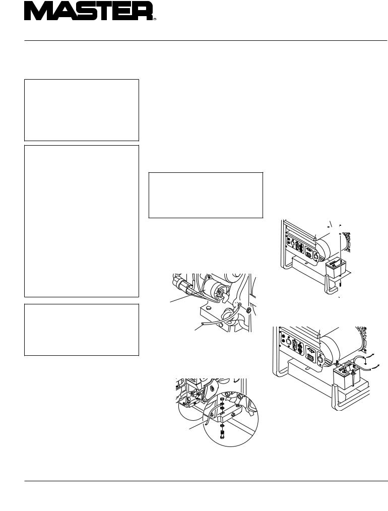
INSTALLING BATTERY CABLES TO ENGINE
1.Attach the red, positive (+) battery cable to the starter solenoid on engine (see Figure 8). This cable is factory installed.
 CAUTION:Donotovertighten positive terminal on starter solenoid. Positive terminal could rotate and cut into negative terminal, causing a short.
2.Attachtheblack,negative(–)batterycable totheengineblock.Usethebolt,nut,and two washers provided with the battery cables. Use long mounting hole on opposite side of engine from starter solenoid. Attach cable as shown in Figure 9.
Starter 


Solenoid
Red, Positive (+)
Battery Cable
Figure 8 - Connecting Red, Positive (+) Battery Cable to Engine Starter Solenoid (Model MGH6500AIE Shown)
MOUNTING BATTERY TO GENERATOR
1.Secure battery to generator by battery hold-down system. This system consists of the battery mounting bracket, hook bolts, and nut (see Figure 10).
2.Locate the red, positive (+) battery cable from starter solenoid. Connect it to the positive (+) battery terminal (see Figure 11).
3.Locate the black, negative (–) battery cableattachedtoengineblock.Connect it to the negative (–) battery terminal (see Figure 11).
4.Check battery before starting engine. Make sure fluid levels are full. Make sure battery is charged.
See engine owner’s manual for more information.
Battery Mounting Bracket
 Nut
Nut

 Battery
 Hook Bolt
Figure 10 - Battery Hold-Down System
(Model MGH6500AIE Shown)
|
POWER |
TO ENGINE |
FULL |
BLOCK |
|
120 |
|
|
ONLY |
|
|
|
|
120 |
|
|
240V |
EN |
|
|
00000M |
|
|
HOURS |
005 |
|
|
1/10 |
|
TO STARTER
SOLENOID
Black,
Negative (–)
Battery Cable
Figure 9 - Connecting Black, Negative (-) Battery Cable to Engine Block (Model MGH6500AIE Shown)
Figure 11 - Connecting Positive and Negative Cables to Battery
(Model MGH6500AIE Shown)
8 |
118683 |
OWNER’S MANUAL
EXTENSION CORDS
Onlyusegroundedextensioncords.Besure touseextensioncordwithproperwiregauge size. See chart below.
Recommended Minimum Wire Gauges (AWG) for Extension Cords
Ampere |
AWG for Length of |
||||
Load |
|
Cord in Feet |
|
||
|
50' |
|
100' |
|
150' |
|
|
|
|
|
|
2 |
18 |
|
18 |
|
18 |
3 |
18 |
|
18 |
|
18 |
4 |
16 |
|
16 |
|
16 |
5 |
16 |
|
16 |
|
16 |
6 |
16 |
|
16 |
|
14 |
8 |
16 |
|
14 |
|
12 |
10 |
16 |
|
14 |
|
12 |
12 |
14 |
|
14 |
|
12 |
14 |
14 |
|
12 |
|
10 |
16 |
12 |
|
12 |
|
10 |
20 |
10 |
|
10 |
|
8 |
|
|
|
|
|
|
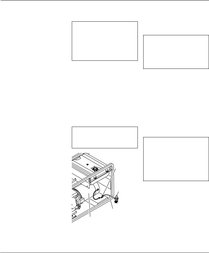
GENERATOR
GROUNDING
 WARNING:You must properly earth-ground generator before starting. This will help guard againstdeadlyelectricshock.Only use grounded plugs with generator.Only use grounded extension cords. Only use three-wire or double-insulated power tools.
Grounding generator helps prevent electric shockfromagroundfaultcondition.Locate ground lug on roll cage (see Figure 12). Attach a #10 stranded-copper ground wire to ground lug. Drive grounding point into ground. Grounding point can be a stake, grounding rod, or pipe. Grounding point should be copper or brass. Attach ground wire to grounding point. You must supply thegroundwireandgroundingpoint.These do not come with generator. Follow the
National Electrical Code and all state and local codes. Consult your power company or a licensed electrician.
 WARNING: For a grounding point, do not use metal pipe being used to carry combustible materials or gases.
Ground Lug
Copper or Brass Grounding Point
Ground Wire
Alternator
Figure 12 - Grounding Generator
(Model MGH4000D Shown)
STANDBY INSTALLATION TO HOME OR BUILDING
 WARNING: Have standby installation performed by a skilled, licensed electrician. Do not let anyone else wire into a utility circuit. Personal injury, equipmentdamage,ordamagetohome could occur.
IMPORTANT: This generator will not power your entire home. Most home utility electric service is more than 60 amps. This will exceed generator output. Only power needed items during a power outage. Make sure total wattage of electrical load does not exceed rated wattage of generator.
You may need to use this generator as a standby power source. During a power outage,thegeneratorwillpowerselecteditems inabuilding.Havegeneratorandadditional wiring installedbyaskilled,licensedelectrician.This is not a do-it-yourself job. Follow all local codes.
 WARNING: The electrician must install a double-throw transfer switch.This isolates existing electrical circuits from the utility power line. If not isolated, generator output will back-feed into utility power line. This may electrocuteapowercompanyline repair person.
118683 |
9 |

R
PORTABLE GASOLINE GENERATORS
DETERMINING ELECTRICAL LOAD FOR GENERATOR
You must decide what electrical load your generator can power. Do this before using generator. Use the following four-step method. It will help you select a load that is not too large. Make sure total wattage of all electrical loads does not exceed rated wattage of generator. For rated wattage of your generator, see Specifications, page 5. Electric motors present a special problem when figuring load. Read Step 3 carefully.
1.Make two lists of items you want powered by generator. List all motors and motor powered appliances in one. List all lights, small appliances, etc. in the other. For standby service to home or building, only include items you must power.
2.Enter running watts of each item except motors. The light bulb or appliance nameplate lists its wattage. Remember, 1KW = 1000 watts. Note: The nameplate may not list wattage. It may only list volts and amps. The formula for finding wattage is: Volts x Amps = Watts. For example: An appliance nameplate states 3 amps at 120 volts. 3 amps x 120 volts = 360 watts.
3.Electric motors present a special problem. They require up to three-times their rated wattage to start. Chart 2, below,showsstartingwattsfordifferent size motors. For example: an electric motor nameplate states 5 amps at 120 volts. 5 amps x 120 volts = 600 watts running. Multiply this figure by 3.This willshowthestartingwattsneeded.600 watts x 3 = 1800 watts to start. When figuring the generator load for motors, you must use the starting watts figure.
Do not use the running watts figure. Note: Some motors require nearly the same wattage to run as to start. These items include saws, drills, hair dryers, andfoodmixers.SeeChart1fortypical appliance wattage examples.
4.Add watts and starting watts of all items.This total must not be larger than the rated wattage of your generator. It is a good idea to have up to 25% extra capacity for future needs or extra equipment.
Typical Electric Appliance Wattages
Chart 1
|
Running |
Starting |
Equipment |
Watts |
Watts |
|
|
|
Light bulb (100W) |
100 |
100 |
Radio |
|
|
150 |
150 |
|
Fan |
|
|
200 |
600 |
|
Television |
|
|
400 |
400 |
|
Furnace fan (1/3 hp) |
|
|
600 |
1800 |
|
with blower |
|
|
Vacuum cleaner |
|
|
600 |
750 |
|
Sump pump (1/3 hp) |
|
|
700 |
2100 |
|
Refrigerator/freezer |
|
|
800 |
2400 |
|
6" Circular saw |
|
|
800 |
1000 |
|
Floodlight |
|
|
1000 |
1000 |
|
1/2" Drill |
|
|
1000 |
1250 |
|
Toaster |
|
|
1200 |
1200 |
|
Coffee maker |
|
|
1200 |
1200 |
|
Skillet |
|
|
1200 |
1200 |
|
14" Chain saw |
|
|
1200 |
1500 |
|
Water well pump |
|
|
1000 |
3000 |
|
(1/2 hp) |
|
|
Hot plate/range |
|
|
1500 |
1500 |
|
(per burner) |
|
|
10" Table saw |
|
|
2000 |
6000 |
|
Water heater |
|
|
5000 |
5000 |
|
(storage-type) |
|
|
Chart 2
|
|
Approximate Starting Watts* |
|
||
|
|
|
|
|
|
Motor |
Approximate |
Universal |
Repulsion |
|
Split |
HP |
Running |
Motors |
Induction |
Capacitor |
Phase |
Rating |
Watts |
(small appliance) |
Motors |
Motors |
Motors |
|
|
|
|
|
|
1/8 |
500 |
625 |
1100 |
1500 |
2250 |
1/4 |
|
|
1550 |
2100 |
3150 |
700 |
875 |
||||
1/3 |
|
|
1750 |
2400 |
3600 |
800 |
1000 |
||||
1/2 |
|
|
2400 |
3300 |
4950 |
1100 |
1375 |
||||
3/4 |
|
|
3100 |
4200 |
x |
1400 |
1750 |
||||
1 |
|
|
3750 |
5100 |
x |
1700 |
2125 |
||||
1 1/2 |
|
|
4620 |
6300 |
x |
2100 |
2625 |
||||
2 |
|
|
5400 |
7350 |
x |
2450 |
3075 |
||||
3 |
|
x |
7900 |
10800 |
x |
3600 |
|||||
|
|
|
|
|
|
* – Always use starting watts, not running watts, when figuring correct electrical load. x – Motors of higher horsepower are not generally used.
10 |
118683 |
 Loading...