


 Loading...
Desa VDVF36TCLPE, DVF36TCR, DVF36CR, VDVF36TCRPE, DVF36TCL User Manual
...DIRECT-VENT CORNER UNIT FIREPLACE OWNER’S OPERATION AND INSTALLATION MANUAL
Right Side Corner
Model Shown
NATURAL GAS MODELS
(V)DVF36TCR(E) AND (V)DVF36TCL(E) (V)DVF36TCR(-HA) AND (V)DVF36TCL(-HA) PROPANE/LP GAS MODELS (V)DVF36TCRP(E) AND (V)DVF36TCLP(E)
WARNING: If the information in this manual is not followed exactly, a fire or explosion may result causing property damage, personal injury or loss of life.
—Do not store or use gasoline or other flammable vapors and liquids in the vicinity of this or any other appliance.
—WHAT TO DO IF YOU SMELL GAS
•Do not try to light any appliance.
•Do not touch any electrical switch; do not use any phone in your building.
•Immediatelycallyourgassupplierfromaneighbor’s phone. Follow the gas supplier’s instructions.
•If you cannot reach your gas supplier, call the fire department.
—Installationandservicemustbeperformedbyaqualified installer, service agency or the gas supplier.
INSTALLER: Leave this manual with the appliance CONSUMER: Retain this manual for future reference.
For more information, visit www.desatech.com
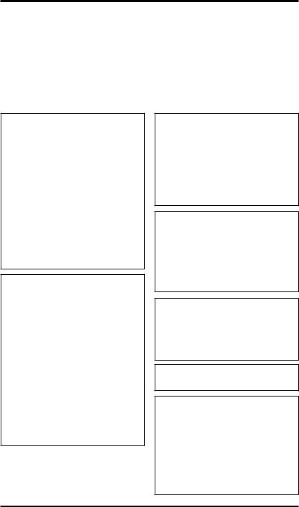
Table of Contents
Safety Information................................................ |
2 |
Operating Fireplace............................................ |
26 |
Dimensions.......................................................... |
5 |
Specifications..................................................... |
28 |
Pre-Installation Preparation.................................. |
5 |
Service Hints...................................................... |
28 |
General Venting.................................................... |
8 |
Technical Service............................................... |
28 |
Venting Installation Instructions.......................... |
10 |
Replacement Parts............................................. |
28 |
Installation.......................................................... |
18 |
Troubleshooting................................................. |
29 |
Pilot/Electrode Assembly Adjustment................. |
23 |
Wiring Diagrams................................................. |
31 |
Burner Flame Adjustment................................... |
24 |
Parts and Accessories........................................ |
32 |
Cleaning and Maintenance................................ |
25 |
Warranty Information............................ |
Back Cover |
Safety Information
WARNING: Improper installation, adjustment, alteration, service or maintenance can cause injury orpropertydamage.Refer to this manual for correct installationandoperational procedures. For assistance or additional information consult a qualified installer, service agency or the gas supplier.
This appliance may be installed in an aftermarket,* permanently located, manufactured (mobile) home, where not prohibited by local codes.
This appliance is only for use with the type of gas indicated on the rating plate. This appliance is not convertible for use with other gases, unless a certified kit is used.
* Aftermarket: Completion of sale, not for purpose of resale, from the manufacturer
This Direct-Vent Gas Fireplace Heater series is intended for use with natural or propane/LP gas only. Do not attempt to burn any solid fuels in these appliances.
State of Massachusetts: The installation must be made by a licensed plumber or gas fitter in the Commonwealth of
Massachusetts.
 WARNING:Thisproductcontainsand/orgenerateschemicals known to the State of California to cause cancer or birth defects or other reproductive harm.
IMPORTANT:Checklocalcodes before installing this fireplace.
IMPORTANT: Read this owner’s manualcarefullyandcompletely before trying to assemble, operate or service this fireplace.
Improper use of this fireplace cancauseseriousinjuryordeath from burns, fire, explosion, electrical shock and carbon monoxide poisoning.
www.desatech.com |
112108-01C |
Safety Information
Continued
 DANGER:Carbonmonoxide
poisoning may lead to death!
Before beginning the installation of the fireplace, read these instructions through completely.
•This DESA fireplace and its components are safe when installed according to this installation manual. Unless you use DESA components, which have been designed and tested for the fireplace system, you may cause a fire hazard.
•The DESA warranty will be voided by and DESA disclaims any responsibility for the following actions:
a)Modification of the fireplace, components, doors, air inlet system and damper control.
b)Use of any component part not manufactured or approved by DESA in combination with a DESA fireplace system.
c)Installation and/or operation in a manner other than instructed in this manual.
d)Burning of anything other than the type of gas approved for use in this gas appliance.
This appliance, when installed, must be electrically grounded in accordance with local codes, or in the absence of local codes, with the National Electrical Code, ANSI/NFPA 70 or CSA C22.1 Canadian Electrical Code for Canada.
The installation must conform to local codes, or in the absence of local codes, with the National Fuel Gas Code ANSI Z223.1 (CAN B149. in CANADA)
This appliance complies with ANSI Z21.50, and CSA 2.22-2000 as a VENTED GAS FIREPLACE and is listed and tested by the Canadian Standards Association.
Proper installation is the most important step in ensuring safe and continuous operation of the fireplace. Consult the local building codes as to the particular requirements concerned with the
installation of all factory built fireplaces.
Thisfireplacemustbeinstalledbyaqualified(cer- tified or licensed) service person. It has a sealed gas combustion chamber that uses a millivolt gas control valve with a millivolt ignition system.
Models (V)DVF36TCR, (V)DVF36TCRP, (V)DVF36TCL and (V)DVF36TCLP are direct- vent fireplaces with sealed combustion chambers that use a millivolt gas control valve with a millivolt ignition system.
Modles (V)DVF36TCRE, (V)DVF36TCRPE, (V)DVF36TCLE and (V)DVF36TCLPE use a direct spark ignition with a 24 VAC control module. All models have HI/LO valve that controls the flame height.
Fan Kit models DVFFBK and DVFFBKT are available for these units as an option. If you are uncertain as to what gas your unit is equipped for, please check the rating plate located in the interior of the appliance opening or consult your local distributor of DESA products.
Carbon Monoxide Poisoning: Early signs of carbon monoxide poisoning resemble the flu, with headaches, dizziness or nausea. If you have these signs, the fireplace may not be working properly. Get fresh air at once! Have fireplace serviced.
Some people are more affected by carbon monoxide than others. These include pregnant women, people with heart or lung disease or anemia, those under the influence of alcohol and those at high altitudes.
NaturalandPropane/LPGas:Natural and propane/ LP gas are odorless. An odor-making agent is added to the gas. The odor helps you detect a gas leak. However, the odor added to the gas can fade. Gas may be present even though no odor exists.
Make certain you read and understand all warnings. Keep this manual for reference. It is your guide to safe and proper operation of this fireplace.
 WARNING: Any change to thisfireplaceorit’scontrolscan be dangerous. Do not modify this fireplace under any circumstances. Any parts removed for servicingmustbereplacedprior to operating fireplace.
 WARNING:Donotuseablowerinsert,heatexchangerinsertor otheraccessorynotapprovedfor use with this fireplace.
 WARNING: This appliance is only for use with the type of gasindicatedontheratingplate.
Thisapplianceisnotconvertible for use with other gases unless a certified kit is used.
112108-01C |
www.desatech.com |
Safety information
Continued
 WARNING: Do not allow fans toblowdirectlyintothefireplace. Avoidanydraftsthatalterburner flame patterns.
Due to high temperatures, the appliance should be located out oftrafficandawayfromfurniture and draperies.
Do not place clothing or other flammable material on or near the appliance. Never place any objects on the appliance.
Donotusethisfireplacetocook foodorburnpaperorotherflammable material.
Thisfireplacereacheshightemperatures. Keep children and adults away from hot surface to avoidburnsorclothingignition. Fireplace will remain hot for a time after shutdown. Allow surface to cool before touching.
Carefully supervise young children when they are in the room with fireplace.
Keep the area around your fireplace clear of combustible materials, gasoline and other flammable vapor or liquids. Do not run fireplace where these are used or stored.
1.For propane/LP fireplace, do not place pro- pane/LP supply tank(s) inside any structure. Locate propane/LP supply tank(s) outdoors. To prevent performance problems, do not use propane/LP fuel tank of less than 100 lbs. capacity.
2.If you smell gas
•shut off gas supply
•do not try to light any appliance
•do not touch any electrical switch; do not use any phone in your building
•immediately call your gas supplier from a neighbor’s phone. Follow the gas supplier's instructions
•if you cannot reach you gas supplier, call the fire department.
3.Never install the fireplace
•in a recreational vehicle
•in windy or drafty areas where curtains or other combustible (flammable) objects can make contact with the fireplace front
•in high traffic areas
4.Turnfireplaceoffandletcoolbeforeservicing, installingorrepairing.Onlyaqualifiedservice person should install, service or repair this fireplace. Have fireplace inspected annually by a qualified service person.
5.You must keep control compartments, burners and circulating air passages clean. More frequent cleaning may be needed due to excessive lint and dust from carpeting, bedding material, etc. Turn off the gas valve and pilot light before cleaning fireplace.
6.Have venting system inspected annually by a qualifiedserviceperson.Ifneeded,havevent- ing system cleaned or repaired. See Operating Guidelines and Maintenance Instructions, page 25.
7.Do not use any solid fuels (wood, coal, paper, cardboard, etc.) in this fireplace. Use only the gas type indicated on fireplace nameplate.
8.Do not use fireplace if any part has been ex- posed to or under water. Immediately call a qualifiedservicepersontoarrangeforreplace- ment of the unit.
9.Do not operate fireplace if any log is broken.
10.Do not operate fireplace with glass door removed, cracked or broken.
11.Provide adequate clearances around air openings.
12.Fireplaces with the suffix of -HA have been designed to operate at altitudes of 4000 feet and above. For horizontal installations above 2,000 feet, it is recommened that a 12" extension pipe be added before starter elbow (see
High Altitude Installation, page 17).
www.desatech.com |
112108-01C |
|
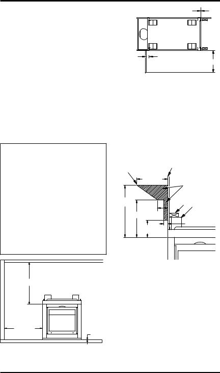
Dimensions |
TOP VIEW |
BACK VIEW |
(Back)
(Left Side) |
|
|
1115/16" |
|
(Front) |
24" |
|
|
1 1/2"ø |
1 1/2"ø |
|
(Right Side) |
|
|
10 1/2" |
10 1/2" |
|
39 3/4"
34 3/4"
26 3/8" |
|
22 5/8" |
3" |
1" |
3" |
|
3 1/2" |
|
|
|
RIGHT SIDE |
|
FRONT VIEW |
1 7/8" |
|
|
|
|
30" |
22 5/8" |
|
(Opening) |
32"(Opening) |
1 7/8" |
19 7/8" |
|
|
(Opening) |
41 |
1/8" |
25" |
|
|
Figure 1 - Dimensions for Left/Right Side Corner Unit
Pre-Installation
Preparation
Location and space
requirements
Determine the safest and most efficient location for your DESA direct-vent fireplace. Make sure that rafters and wall studs are not in the way of the venting system. Choose a location where the heat output is not affected by drafts, air conditioning ducts, windows or doors. Be aware of all restrictions and precautions before deciding the exact location for your fireplace and termination cap.
When deciding the location of your fireplace, follow these rules:
•A projection may be ideal for a new addition onanexistingfinishedwall.Refertohorizontal termination configurations on page 13 or verti- cal configurations on page 15.
•Do not connect this fireplace venting to a chim- ney flue serving a separate solid-fuel burning fireplace or appliance.
•Due to high temperatures, do not locate this fireplace in high traffic areas, windy or drafty areas or near furniture or draperies.
•Never obstruct the front opening of the appli- ance or flow of combustion and ventilation air.
Keep control compartments accessible.
•Do not locate close to where gasoline or other flammableliquidsmaybestored.Theappliance must be kept clear and free from combustible materials.
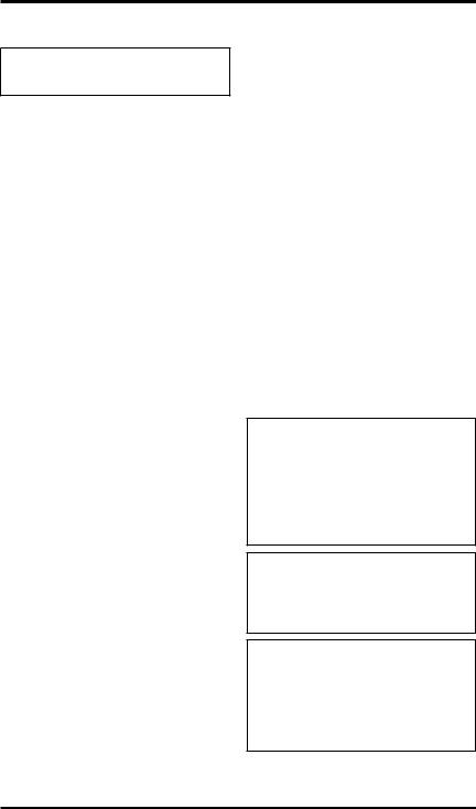
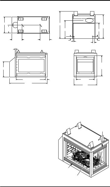
Upper
Louver
Panel
Lower |
|
Louver |
|
Panel |
Log Set |
|
Figure 2 - Direct-Vent Fireplace
112108-01C |
www.desatech.com |
Pre-Installation
Preparation
Continued
Clearances
Minimum clearances to combustibles for the fire- |
|
place are as follows: |
|
Back and Sides of Surround* |
0" |
Vent Surface (Side and Bottom) |
1" |
Top Vent Surface (Horizontal Run) |
2" |
Ceiling to Opening |
36" |
Floor |
0" |
Wall to Front of Glass |
36" |
Perpendicular Wall to Opening of Unit |
2" |
Top Spacer |
0" |
* For back and sides of fireplace, do not pack with insulation or other materials. Zero inch clearance to combustible materials are for framing purpose only.
NOTICE: This fireplace is intended for use as supplemental heat. Use this fireplace along with your primary heating system. Do not install this fireplace as your primary heat source. If you have a central heating system, you may run system’s circulating blower while using fireplace.Thiswillhelpcirculate the heat throughout the house.
In the event of a power outage, you can use this fireplace as a heat source.
CEILING
Left Side |
TOP VIEW |
0" |
Surround |
|
|
(0" Min.) |
|
|
Right Side |
|
|
Surround |
2" |
|
(0" Min.) |
36" |
|
|
Wall In Front Of Glass |
|
Perpendicular |
|
|
36" Min. |
|
|
Wall 2" Min. |
|
|
|
|
|
From Opening |
|
|
Figure 4 - Minimum Clearances
Mantel Clearances
Woodwork, such as wood trims, mantels and other combustible materials should not be placed within
7" of the opening of this fireplace (see Figure 5).
Combustible material above projecting more than
11/2" from the appliance’s front face must not be placed less than 15" from the opening of the appliance (ref. NFPA Standard 211 Sec. 7-3.3.3).
Combustible |
|
Drywall (Gypsum |
|
Material May |
|
Board, Sheetrock, Etc.) |
|
Be Used |
|
Safe Zone for |
|
|
|
||
12" Min. |
Projection of |
||
|
|
Combustible |
|
|
|
Material |
|
21" Min. |
4" |
2 x 4 |
Spacer |
|
Min. |
|
|
|
|
|
|
15" Min. |
|
|
|
|
|
1 1/2" Max. |
|
7" Min. |
|
UNIT |
|
|
|
|
|
Figure 5 - Mantel Clearances |
|||
36" Min.
WALL
36" Min.
0" Floor
Figure 3 - Minimum Clearances
framing
Once the final location has been determined, ob- serving clearances for the vent termination, you may construct framing using dimensions shown in Figures 6 to 10 on page 7 depending on your particular installation
If the appliance is to be installed directly on carpeting, tile (other than ceramic), or any combustible mate- rial other than wood flooring, the appliance must be installed upon a metal or wood panel extending the full width and depth of the appliance. There are three holes on each side of the bottom of the unit where screws can be used to secure the unit to the floor.
www.desatech.com |
112108-01C |

Pre-Installation
Preparation
Continued
The gas supply line may be connected through the side framing or alternately through the lower sub-flooring or a platform base if provided (see
Figures 8). Depending on installation, refer to appropriate illustrations.
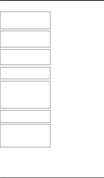
20
3 / 16
"
1
10
1 / 2"
1 / 2"
" /16 15 11

 40
40
1 / 2"
24"
39 3/4" Min.
Figure 8 - Alternate Gas Supply Location
10 3/4"  Square
Min. 
Figure 6 - Rough Opening for Fireplace
Height
Depends
On
Installation
 24"
24"
|
|
|
|
39 3/4" |
|
|
|
|
Min. |
Platform |
|
|
|
|
Must Be |
|
|
|
|
Solid, Flat, |
|
|
|
|
and Fully |
40 |
1 |
|
|
Supported |
" |
|
||
|
|
/ |
|
|
|
|
2 |
* |
|
|
|
|
|
|
* As required by design as long as ceiling clearance is maintained.
Figure 7 - Rough Opening for Installing Fireplace on Platform
Figure 9 - Rough Opening for Installing Exterior Vent Terminal
90o  Elbow
Elbow
45o
Elbow
Vertical
Height Depends on Installation
26 3/8"
 Horizontal
Length Depends
on Installation
Figure 10 - Vent Opening Height
112108-01C |
www.desatech.com |
|

General Venting
These models are approved for use with DESA 58 Series, rigid type direct vent pipe as supplied by
DESAorwithapprovedtypesofflexibleventpipe
(not supplied) when appropriately sized for an 8" outer and 5" inner diameter application.
Yourfireplaceisapprovedtobeventedeitherhori- zontally through a side wall, or vertically through a roofline using the following guidelines:
•Only use DESA supplied or approved types of venting components or kits. Do not mix different types of vent components, modify vent components or custom fabricate vent components for use in any one installation.
•Minimum clearance between vent pipes and combustible materials is 1", except where stated otherwise.
•Combustiblematerialmaybeflushwiththetop front of fireplace with a maximum thickness of 3/4".
•Do not recess venting terminals into a wall or siding.
•Do not install vent terminals below grade level. Maintain a minimum height of 12" above snow line.
•Do not terminate venting system into an attic or garage.
•If using a venting configuration of only hori- zontal venting with no vertical run, a 1/4" rise for every 12" of run toward the termination is required.
•There must not be any obstruction such as bushes, garden sheds, fences, decks, or utility buildings within 24" from the front of the termination cap.
•Do not locate termination cap where excessive snow or ice build up may occur. Be sure to clear vent termination area after snow falls to prevent accidental blockage of venting system. When using snow blowers, do not direct snow towards vent termination area.
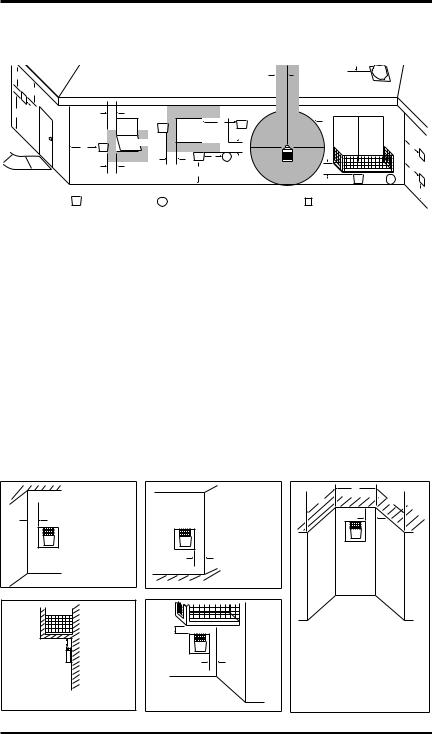
Vent Termination Clearances
The final position of your appliance depends on the location of the vent termination in relation to the clearances that must be observed as shown in Figure 11, page 9.
You may avoid extra framing by positioning your fireplaceagainstanalreadyexistingframingmem- ber. The back of the fireplace may be positioned directly against a combustible wall.
*Check with local codes or with the CANCGA B149.1 or B149.2 Installation Codes for Canada installations. In the USA, follow the current National Fuel Gas Fuel Gas Code, ANS Z223.1 also known as NFPA 54.
www.desatech.com |
112108-01C |
General Venting
D
E  V
V
B L 
|
|
|
Continued |
|
|
|
|
|
|
|
H |
|
C |
|
|
|
|
|
Fixed |
V |
B |
V |
I |
|
Closed |
Openable Fixed |
|
|
|
|
Openable |
|
Closed |
|
|
F |
|
|
B |
|
|
V |
|
|
|
||
|
B |
V J |
X |
G |
|
|
|
|
|
B |
|
A |
|
M |
|
|
|
V  K
K  X
X
G V
G V
|
|
|
|
|
|
|
|
|
|
|
A |
|
|
|
V TERMINATION CAP |
X AIR SUPPLY INLET |
|
G |
GAS METER |
|
|
RESTRICTED AREA |
|
||
|
|
|
|
|
||||||||
|
|
|
|
|
|
|
|
|
|
|
(TERMINATION PROHIBITED) |
|
A |
= |
clearance above grade, veranda, porch, deck, or |
I |
= |
clearance to service regulator vent outlet [*72" (182.9 cm) |
|||||||
|
|
balcony [*12" (30.5 cm) minimum] |
|
|
|
minimum] |
|
|
||||
B |
= |
clearance to window or door that may be opened |
J |
= |
clearance to non-mechanical air supply inlet to building |
|||||||
|
|
[6" (15 cm) min. for 10,000 Btu or less; 9" (23 cm) in US |
|
|
or the combustion air inlet to any other fireplace |
|||||||
|
|
if between 10,000 and 50,000, 12" (30 cm) in Canada |
|
|
[6" (15 cm) min. for 10,000 Btu or less; 9" (23 cm) in US |
|||||||
|
|
if between 10,000 and 100,000; 12" (30 cm) in US if |
|
|
if between 10,000 and 50,000, 12" (30 cm) in Canada |
|||||||
|
|
greater than 50,000, 36" (91 cm) in Canada if greater |
|
|
if between 10,000 and 100,000; 12" (30 cm) in US if |
|||||||
|
|
than 100,000] |
|
|
|
greater than 50,000, 36" (91 cm) in Canada if greater |
||||||
C |
= |
clearance to permanently closed window |
|
|
|
than 100,000] |
|
|
||||
|
|
[minimum 12" (30.5 cm) recommended to prevent |
K |
= |
clearance to a mechanical air supply inlet [*In Canada, |
|||||||
|
|
condensation on window] |
|
|
|
6 ft. (1.83m) minimum; In US 3 ft. (91 cm) above if within |
||||||
D |
= |
vertical clearance to ventilated soffit located above the |
|
|
10 ft. (3 m) horizontally] |
|
|
|||||
|
|
terminal within a horizontal distance of 24" (61 cm) from L |
= |
† clearance above paved side-walk or a paved driveway |
||||||||
|
|
the center-line of the terminal [18" (45.7 cm) minimum] |
|
|
located on public property [*84" (213.3 cm) minimum] |
|||||||
E |
= |
clearance to unventilated soffit [12" (30.5 cm) minimum] M = |
clearance under veranda, porch, deck |
|||||||||
F |
= |
clearance to outside corner (see below) |
|
|
|
[*12" (30.5 cm) minimum ‡] |
||||||
G |
= |
clearance to inside corner (see below) |
|
N = |
clearance above a roof shall extend a minimum of |
|||||||
H |
= |
*not to be installed above a meter/regulator assembly |
|
|
24" (61 cm) above the highest point when it passes |
|||||||
|
|
within 36" (91.4 cm) horizontally from the center line |
|
|
through the roof surface and any other obstruction within |
|||||||
|
|
of the regulator |
|
|
|
a horizontal distance of 18" (45.7 cm) |
||||||
†vent shall not terminate directly above a side-walk or paved driveway which is located between two single family dwellings and serves both dwellings*
‡ only permitted if veranda, porch, deck or balconey is fully open on a minimum of 2 sides beneath the floor* * as specified in CAN/CSA B149 (.1 or .2) Installation Codes (1991) for Canada and U.S.A.
Note: Local codes or regulations may require different clearances
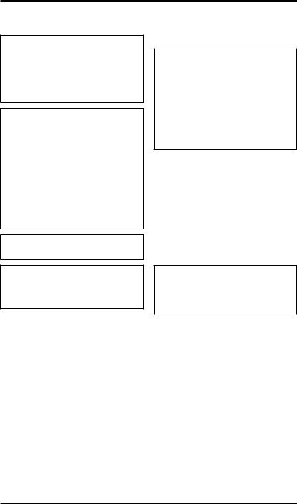
Termination Clearances for Buildings with Combustible and Noncombustible Exteriors
Inside Corner |
|
Outside Corner |
Recessed Location |
|
|
|
|
D |
|
|
|
|
C |
C |
A |
A = 6" (15.2 cm) |
|
|
E |
|
|
|
||
V |
|
V |
V |
|
|
|
|
||
|
|
B = 6" (15.2 cm) |
|
|
|
|
B |
|
|
Balcony with No Side Wall |
Balcony with Perpendicular Side Wall |
|
|
|
|
H |
C = Maximum depth of 48" (121.9 cm) |
|
G |
|
for recessed location |
|
V |
D = Minimum width for back wall of |
||
V |
|
recessed location - |
|
J |
Combustible - 38" (965 mm) |
||
|
|||
|
|
Noncombustible - 24" (61 cm) |
|
|
Combustible & |
E = Clearance from corner in |
|
|
recessed location- |
||
|
Noncombustible |
||
|
Combustible - 6" (15.2 cm) |
||
G = 12" (30.5 cm) minimum clearance |
H = 24" (61 cm) |
||
Noncombustible - 2" (5.1 cm) |
|||
|
J = 20" (50.8 cm) |
||
Figure 11 - Minimum Clearances for Termination Cap |
|||
112108-01C |
www.desatech.com |
Venting Installation
Instructions
 WARNING: Read all instructionscompletelyandthoroughly before attempting installation.
Failure to do so could result in seriousinjury,propertydamage or loss of life.
 WARNING: Seal all connections with high temperature silicone every time a vent connection is made. Before joining elbows or pipes, apply a bead of high temperature silicone sealant to the male end of the elboworpipe.Hightemperature siliconemustalsobeusedtoresealanyconnectionsaftermaintenance to venting system.
NOTICE:Failuretofollowtheseinstructions will void the warranty.
NOTICE:Donotsealtermination cap to vent pipe. Cap must be removable for vent inspection and maintenance.
Installation Precautions
Consult local building codes before beginning the installation. The installer must make sure to select the proper vent system for installation. Before installing vent kit, the installer must read this fireplace manual and vent kit instructions.
Only a qualified service person should install venting system. The installer must follow these safety rules:
•Wear gloves and safety glasses for protection
•Use extreme caution when using ladders or when on roof tops
•Be aware of electrical wiring locations in walls and ceilings
The following actions will void the warranty on your venting system:
•Installation of any damaged venting component
•Unauthorized modification of the venting sys- tem (Do not cut or alter vent components)
•Installation of any component part not manufactured or approved by DESA
•Installation other than as instructed by these instructions
 WARNING: This gas fireplace andventassemblymustbevented directlytotheoutside.Theventing system must NEVER be attached to a chimney serving a separate solidfuelburningappliance.Each direct-vent gas appliance must useaseparateventsystem.Donot use common vent systems.
INSTALLATION PLANNING
There are two basic types of direct-vent installation:
•Horizontal Termination
•Vertical Termination
It is important to select the proper length of vent pipe for the type of termination you choose. It is also important to note the wall thickness.
For Horizontal Termination: Select the amount of vertical rise desired. The horizontal run of venting must have 1/4" rise for every 12" of run towards the termination.
 WARNING: Never run the vent downward as this may cause excessive temperatures which could cause a fire.
You may use one or two 90° elbows in this vent configuration. See Horizontal Termination Con- figurations on page 13.
For Vertical Termination: Measure the distance from the fireplace flue outlet to the ceiling. Add the ceiling thickness, the vertical rise in an attic or second story, and allow for sufficient vent height above the roof line. You may use one or two 90° elbows in this vent configuration. See Vertical
Termination Configurations on page 16.
Note: You may use two 45° elbows in place of a 90° elbow. You must follow rise to run ratios when using 45° elbows.
Fortwo-storyapplications,firestopsarerequiredat each floor level. If an offset is needed in the attic, additional pipe and elbows will be required.
You may use a chase with a vent termination with exposed pipe on the exterior of the house. See Installing Vent System in a Chase, page 11.
10 |
www.desatech.com |
112108-01C |
Venting Installation instructions
Continued
Your DESA direct-vent fireplace has been tested for a minimum 3' rise with a maximum 11" wall thickness. Any horizontal application longer than 12" must provide a minimum of 1 foot of vertical rise for every 3 feet of horizontal run. The maximum horizontal run is 20' with 8' vertical rise (see Installation for Horizontal Termination). The maximum vertical run is 30' (see Installation for Vertical Termination, page 114).
Installing Vent System in a Chase
A chase is a vertical box-like structure built to enclose venting that runs along the outside of a building.
NOTICE: Treatment of firestops and construction of the chase may vary from building type to building type. These instructions are not substitutes for the requirements of local building codes. You must follow all local building codes.
Note: When installing in a chase, you should insulate the chase as you would the outside walls of your home. This is especially important in cold climates. Minimum clearance between vent pipes and combustible materials such as insulation is 1".
After framing the chase (see Framing on page 6) install the vent system by following the installation instructions.
installation for horizontal termination
1.Determine the route your horizontal venting will take. Note: The location of the horizontal vent termination on the exterior wall must meet all local and national building codes and must not be blocked or obstructed.
 WARNING: Do not recess vent terminal into a wall or siding. This is a fire hazard.
Snorkel terminations are available for terminations requiring a vertical rise on the exterior of the building (see Figures 12 and 13). Snorkel kits are available for rigid pipe applications only to provide a 14" rise and a 36" rise (see page 17). Follow the same installation procedures used for standard horizontal terminations. If installing the snorkel termination to raise the vent termination from below grade level such as in a basement installation, you must provide proper drainage to prevent water from entering the snorkel termination (see Figure 13). Do not back fill around the snorkel termination.
2.Rigid vent pipes and fittings have special twist-lock connections. Assemble the desired combination of pipe and elbows to the appliance adaptor with pipe seams oriented towards the wall or floor.
Snorkel |
|
90º |
|
12" Minimum |
12" |
|
|
|
Minimum |
45º
Figure 12 - Snorkel Termination
|
Snorkel |
|
90º |
|
|
12" Minimum |
12" |
|
Minimum |
||
|
45°


 Adequate
Drainage
Figure 13 - Snorkel Termination with Drainage Pipe
112108-01C |
www.desatech.com |
11 |
Loading...