


VENT-FREE NATURAL GAS HEATER
OWNER’S OPERATION AND INSTALLATION MANUAL
®
Model: CGN10T and CGN10TL
WARNING: If the information in this manual is not followed exactly, a fire or explosion may result causing property damage, personal injury, or loss of life.
—Do not store or use gasoline or other flammable vapors and liquids in the vicinity of this or any other appliance.
—WHAT TO DO IF YOU SMELL GAS
•Do not try to light any appliance.
•Do not touch any electrical switch; do not use any phone in your building.
•Immediately call your gas supplier from a neighbor’s phone. Follow the gas supplier’s instructions.
•If you cannot reach your gas supplier, call the fire department.
—Installation and service must be performed by a qualified installer, service agency, or the gas supplier.
WARNING: Improper installation, adjustment, alteration, service, or maintenance can cause injury or property damage. Refer to this manual for correct installation and operational procedures. For assistance or additional information consult a qualified installer, service agency, or the gas supplier.
WARNING: This is an unvented gas-fired heater. It uses air (oxygen) from the room in which it is installed. Provisions for adequate combustion and ventilation air must be provided. Refer to Air for Combustion and Ventilation section in this manual.
This appliance may be installed in an aftermarket* manufactured (mobile) home, where not prohibited by state or local codes.
*Aftermarket: Completion of sale, not for purpose of resale, from the manufacturer. (I.E. Installation of this
product is permitted after the manufactured (mobile) home is sited)
This appliance is only for use with the type of gas indicated on the rating plate. This appliance is not convertible for use with other gases.
Save this manual for future reference.
CONTENTS |
SECTION |
PAGE |
|
Safety Information ......................................................................... |
2 |
|
Product Identification .................................................................... |
4 |
|
Local Codes ................................................................................... |
4 |
|
Unpacking ...................................................................................... |
4 |
|
Product Features ............................................................................ |
4 |
|
Air For Combustion and Ventilation ............................................. |
5 |
|
Installing To Wall .......................................................................... |
9 |
|
Connecting To Gas Supply ............................................................ |
13 |
|
Checking Gas Connections ............................................................ |
14 |
|
Operating Heater ........................................................................... |
16 |
|
Inspecting Burner .......................................................................... |
19 |
|
Cleaning And Maintenance ........................................................... |
21 |
|
Troubleshooting ............................................................................. |
21 |
|
Technical Service .......................................................................... |
25 |
|
Specifications ................................................................................ |
25 |
|
Service Hints ................................................................................. |
25 |
|
Illustrated Parts Breakdown .......................................................... |
26 |
|
Parts List ........................................................................................ |
27 |
|
Replacement Parts ......................................................................... |
28 |
|
Service Publications ...................................................................... |
28 |
|
Accessory ...................................................................................... |
28 |
|
Parts Central .................................................................................. |
29 |
|
Warranty Information .................................................................... |
Back Cover |
 WARNINGS
IMPORTANT: Read this owner’s manual carefully and completely before trying to assemble, operate, or service this heater. Improper use of this heater can cause serious injury or death from burns, fire, explosion, and carbon monoxide poisoning.
 DANGER
Carbon monoxide poisoning may lead to death!
Carbon Monoxide Poisoning: Early signs of carbon monoxide poisoning resemble the flu, with headaches, dizziness, and/or nausea. If you have these signs, the heater may not be working properly. Get fresh air at once! Have heater serviced. Some people are more affected by carbon monoxide than others. These include pregnant women, people with heart or lung disease or anemia, those under the influence of alcohol, and those at high altitudes.
Natural Gas: Natural gas is odorless. An odor-making agent is added to natural gas. The odor helps you detect a natural gas leak. However, the odor added to natural gas can fade. Natural gas may be present even though no odor exists.
Make certain you read and understand all Warnings. Keep this manual for reference. It is your guide to safe and proper operation of this heater.
2 |
Safety Information continues on next page |
|
|
|
|
103574

SAFETY INFORMATION
Continued
WARNINGS Continued
WARNING ICON |
G 001 |
WARNING: Any change to this heater or its controls can be dangerous.
1.This appliance is only for use with the type of gas indicated on the rating plate. This appliance is not convertible for use with other gases.
2.If you smell gas
•shut off gas supply
•do not try to light any appliance
•do not touch any electrical switch; do not use any phone in your building
•immediately call your gas supplier from a neighbor’s phone. Follow the gas supplier’s instructions
•if you cannot reach your gas supplier, call the fire department
3.Heater shall not be installed in a bathroom.
4.Never install the heater
•in a recreational vehicle
•where curtains, furniture, clothing, or other flammable objects are less than 36 inches from the front, top, or sides of the heater
•as a fireplace insert
•in high traffic areas
•in windy or drafty areas
5.This heater needs fresh, outside air ventilation to run properly. This heater has an oxygen depletion sensor (ODS) pilot light safety system. The ODS shuts down the heater if not enough fresh air is available. See Air for Combustion and Ventilation, pages 5 through 8.
6.Keep all air openings in front and bottom of heater clear and free of debris. This will insure enough air for proper combustion.
7.If heater shuts off, do not relight until you provide fresh, outside air. If heater keeps shutting off, have it serviced.
8.Do not run heater
•where flammable liquids or vapors are used or stored
•under dusty conditions
9.Never place any objects on the heater.
10.Surface of heater becomes very hot when running heater. Keep children and adults away from hot surface to avoid burns or clothing ignition. Heater will remain hot for a time after shutdown. Allow surface to cool before touching.
11.Carefully supervise young children when they are in same room with heater.
12.Make sure grill guard is in place before running heater.
13.Do not use heater if any part has been under water. Immediately call a qualified service technician to inspect the room heater and to replace any part of the control system and any gas control which has been under water.
14.Turn off heater and let cool before servicing. Only a qualified service person should service and repair heater.
15.Operating heater above elevations of 4,500 feet could cause pilot outage.
3
103574
PRODUCT IDENTIFICATION
LOCAL CODES
UNPACKING
PRODUCT
FEATURES
4
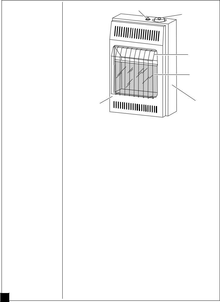
Ignitor Button
Control Knob
Grill
Guard
Glass
Panel
Front
Heater
Panel
Cabinet
Figure 1 - Vent-Free Natural Gas Heater
Install and use heater with care. Follow all local codes. In the absence of local codes, use the latest edition of The National Fuel Gas Code ANSI Z223.1 also known as NFPA 54*.
*Available from:
American National Standards Institute, Inc.
1430 Broadway
New York, NY 10018
National Fire Protection Association, Inc.
Batterymarch Park
Quincy, MA 02269
1.Remove heater from carton.
2.Remove all protective packaging applied to heater for shipment.
3.Check heater for any shipping damage. If heater is damaged, promptly inform dealer where you bought heater.
Safety Device
This heater has a pilot with an Oxygen Depletion Sensor Shutoff System (ODS). The ODS/pilot is a required feature for vent-free room heaters. The ODS/pilot shuts off the heater if there is not enough fresh air.
Piezo Ignition System
This heater has a piezo ignitor. This system requires no matches, batteries, or other sources to light heater.
Thermostatic Heat Control
This heater has a thermostat sensing bulb and thermostat control. This results in the greatest heater comfort. This can also result in lower gas bills.
103574

AIR FOR COMBUSTION AND VENTILATION
WARNING
WARNING ICON |
G 001 |
This heater shall not be installed in a confined space unless provisions are provided for adequate combustion and ventilation air. Read the following instructions to insure proper fresh air for this and other fuel-burning appliances in your home.
Today’s homes are built more energy efficient than ever. New materials, increased insulation, and new construction methods help reduce heat loss in homes. Home owners weather strip and caulk around windows and doors to keep the cold air out and the warm air in. During heating months, home owners want their homes as airtight as possible.
While it is good to make your home energy efficient, your home needs to breathe. Fresh air must enter your home. All fuel-burning appliances need fresh air for proper combustion and ventilation.
Exhaust fans, fireplaces, clothes dryers, and fuel burning appliances draw air from the house to operate. You must provide adequate fresh air for these appliances. This will insure proper venting of vented fuel-burning appliances.
PROVIDING ADEQUATE VENTILATION
The following is exerpts from National Fuel Gas Code. NFPA 54/ANSI Z223.1,
Section 5.3, Air for Combustion and Ventilation.
All spaces in homes fall into one of the three following ventilation classifications: 1. Unusually Tight Contruction; 2. Unconfined Space; 3. Confined Space.
The information on pages 5 through 8 will help you classify your space and provide adequate ventilation.
Unusually Tight Construction
The air that leaks around doors and windows may provide enough fresh air for combustion and ventilation. However, in buildings of unusually tight construction, you must provide additional fresh air.
Unusually tight construction is defined as construction where:
a.walls and ceilings exposed to the outside atmosphere have a continuous water vapor retarder with a rating of one perm (6x10-11 per pa-sec- m2) or less with openings gasketed or sealed and
b.weather stripping has been added on openable windows and doors and
c.caulking or sealants are applied to areas such as joints around window and door frames, between sole plates and floors, between wall-ceiling joints, between wall panels, at penetrations for plumbing, electrical, and gas lines, and at other openings.
If your home meets all of the three criteria above, you must provide additional fresh air. See Ventilation Air From Outdoors, page 8.
If your home does not meet all of the three criteria above, proceed to page 6.
Confined and Unconfined Spaces
The National Fuel Gas Code defines a confined space as a space whose volume is less than 50 cubic feet per 1000 Btu per hour (4.8 cubic meters per kw) of the aggregate input rating of all appliances installed in that space and an unconfined space as a space whose volume is not less than 50 cubic feet per 1000 Btu per hour (4.8 cubic meters per kw) of the aggregate input rating of all appliances installed in that space. Rooms communicating directly with the space in which the appliances are installed, through openings not furnished with doors, are considered a part of the unconfined space.
Continued 5
103574

AIR FOR COMBUSTION AND VENTILATION
Continued
6
DETERMINING AIR FLOW FOR HEATER LOCATION
Determining if You Have a Confined or Unconfined Space
Use this worksheet to determine if you have a confined or unconfined space.
Space: Includes the room in which you will install heater plus any adjoining rooms with doorless passageways or ventilation grills between the rooms.
1. Determine the volume of the space (length x width x height).
Length x Width x Height = ___________________ cu. ft. (volume of space) Example: Space size 18 ft. (length) x 16 ft. (width) x 8 ft. (ceiling height) =
2304 cu. ft. (volume of space)
If additional ventilation to adjoining room is supplied with grills or openings, add the volume of these rooms to the total volume of the space.
2.Divide the space volume by 50 cubic feet to determine the maximum Btu/Hr the space can support.
____________ (volume of space) ÷ 50 cu. ft. = (Maximum Btu/Hr the space can support)
Example: 2304 cu. ft. (volume of space) ÷ 50 cu. ft. = 46.1 or 46,100 (maximum Btu/Hr the space can support)
3. Add the Btu/Hr of all fuel burning appliances in the space.
Vent-free heater |
|
___________________ Btu/Hr |
||
Gas water heater* |
|
___________________ Btu/Hr |
||
Gas furnace |
|
|
___________________ Btu/Hr |
|
Vented gas heater |
|
___________________ Btu/Hr |
||
Gas fireplace logs |
|
___________________ Btu/Hr |
||
Other gas appliances* |
+ ___________________ Btu/Hr |
|||
Total |
= ___________________ Btu/Hr |
|||
Example: Gas water heater |
|
40,000 |
Btu/Hr |
|
Vent-free heater |
+ |
10,000 |
Btu/Hr |
|
Total |
= |
|
|
Btu/Hr |
50,000 |
||||
* Do not include direct-vent gas appliances. Direct-vent draws combustion air from the outdoors and vents to the outdoors.
4. Compare the maximum Btu/Hr the space can support with the actual amount of Btu/Hr used.
_________________ |
Btu/Hr (maximum the space can support) |
_________________ |
Btu/Hr (actual amount of Btu/Hr used) |
Example: 46,100 |
Btu/Hr (maximum the space can support) |
50,000 |
Btu/Hr (actual amount of Btu/Hr used) |
The space in the above example is a confined space because the actual Btu/Hr used is more than the maximum Btu/Hr the space can support. You must provide additional fresh air. Your options are as follows:
A.Rework worksheet, adding the space of an adjoining room. If the extra space provides an unconfined space, remove door to adjoining room or add ventilation grills between rooms. See Ventilation Air From Inside Building, page 7.
B.Vent room directly to the outdoors. See Ventilation Air From Outdoors, page 8.
C.Install a lower Btu/Hr heater, if lower Btu/Hr size makes room unconfined.
If the actual Btu/Hr used is less than the maximum Btu/Hr the space can support, the space is an unconfined space. You will need no additional fresh air ventilation.
103574
AIR FOR COMBUSTION AND VENTILATION
Continued
WARNING
WARNING ICON |
G 001 |
If the area in which the heater may be operated is smaller than that defined as an unconfined space, provide adequate combustion and ventilation air by one of the methods described in the
National Fuel Gas Code, ANSI Z223.1, 1992, Section 5.3 or applicable local codes.
VENTILATION AIR
Ventilation Air From Inside Building
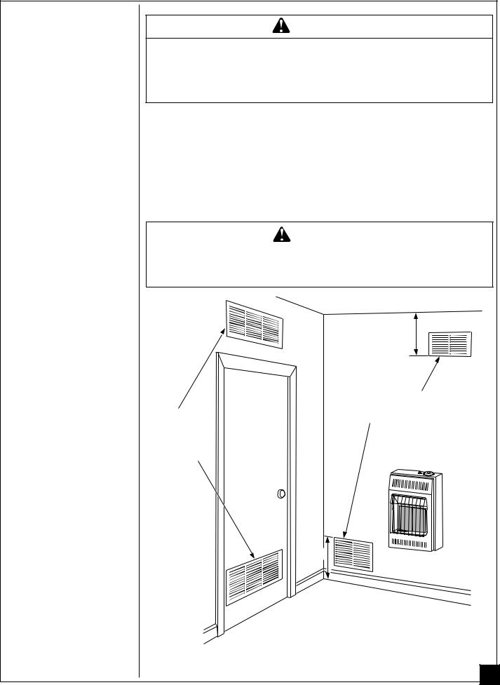
This fresh air would come from an adjoining unconfined space. When ventilating to an adjoining unconfined space, you must provide two permanent openings: one within 12" of the ceiling and one within 12" of the floor on the wall connecting the two spaces (see options 1 and 2, Figure 2). You can also remove door into adjoining room (see option 3, Figure 2). Follow the National Fuel Gas Code NFPA 54/ANSI Z223.1,
Section 5.3, Air for Combustion and Ventilation for required size of ventilation grills or ducts.
WARNING
WARNING ICON |
G 001 |
|
|
Rework worksheet, adding the space of the adjoining unconfined space. The combined spaces must have enough fresh air to supply all appliances in both spaces.
12"
|
Ventilation Grills |
Ventilation |
Into Adjoining Room, |
Option 2 |
|
Grills |
Or |
into Adjoining |
Remove |
Room, |
Door into |
Option 1 |
Adjoining |
|
Room, |
|
Option 3 |
12"
Figure 2 - Ventilation Air from Inside Building
Continued
7
103574
AIR FOR COMBUSTION AND VENTILATION
Continued
8
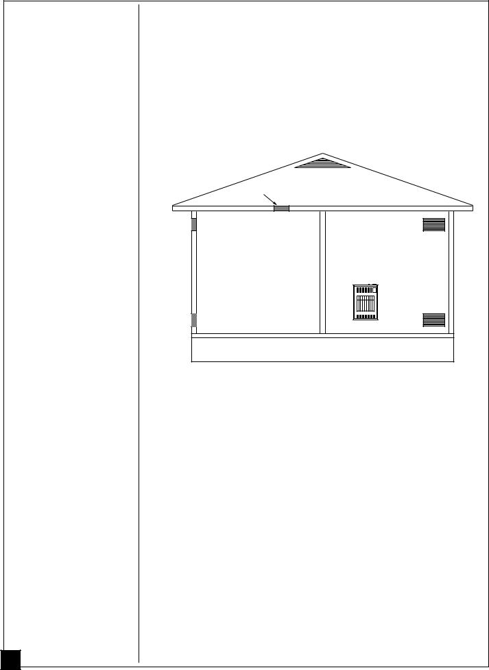
Ventilation Air From Outdoors
Provide extra fresh air by using ventilation grills or ducts. You must provide two permanent openings: one within 12" of the ceiling and one within 12" of the floor. Connect these items directly to the outdoors or spaces open to the outdoors. These spaces include attics and crawl spaces. Follow the National Fuel Gas Code NFPA 54/ANSI Z223.1, Section 5.3, Air for Combustion and Ventilation for required size of ventilation grills or ducts.
IMPORTANT: Do not provide openings for inlet or outlet air into attic if attic has a thermostat-controlled power vent. Heated air entering the attic will activate the power vent.
Ventilated
Outlet Attic
Air
Outlet 

Air
To Attic
To
Crawl
Space
Inlet
Air
|
|
Inlet Air |
|
Ventilated |
|
|
|
|
|
|
Crawl Space |
|
|
|
|
|
|
|
|
Figure 3 - Ventilation Air from Outdoors
103574
INSTALLING TO WALL
NOTICE
A qualified service person must install heater. Follow all local codes.
CHECK GAS TYPE
Use only natural gas. If your gas supply is not natural, do not install heater. Call dealer where you bought heater for proper type heater.
INSTALLATION ITEMS
Before installing heater, make sure you have the items listed below:
• piping (check local codes) |
• test gauge connection * (see |
||
• sealant (resistant to propane/LP gas) |
|
Figure 12, page 14) |
|
• |
manual shutoff valve * |
• sediment trap |
|
• |
ground joint union |
• |
tee joint |
|
|
• |
pipe wrench |
* An A.G.A. design-certified manual shutoff valve with 1/8" NPT tap is an acceptable alternative to test gauge connection. Purchase the optional A.G.A. design-certified manual shutoff valve from your dealer. See Accessory, page 28.
LOCATING HEATER
This heater is designed to be mounted on a wall.
WARNING
WARNING ICON |
G 001 |
Maintain the minimum clearances shown in Figure 4 (page 10). If you can, provide greater clearances from floor, ceiling, and joining wall.
WARNING
WARNING ICON |
G 001 |
Never install the heater
•in a bathroom
•in a recreational vehicle
•where curtains, furniture, clothing, or other flammable objects are less than 36 inches from the front, top, or sides of the heater
•as a fireplace insert
•in high traffic areas
•in windy or drafty areas
CAUTION
WARNING ICON |
G 001 |
This heater creates warm air currents. These currents move heat to wall surfaces next to heater. Installing heater next to vinyl or cloth wall coverings or operating heater where impurities in the air (such as tobacco smoke) exist, may discolor walls.
IMPORTANT: Vent-free heaters add moisture to the air. Although this is beneficial, installing heater in rooms without enough ventilation air may cause mildew to form from too much moisture. See Air for Combustion and Ventilation, pages 5 through 8.
CAUTION
WARNING ICON |
G 001 |
If you install the heater in a home garage
•heater pilot and burner must be at least 18 inches above floor
•locate heater where moving vehicle will not hit it
Continued 9
103574
INSTALLING TO WALL
Continued
10
For convenience and efficiency, install heater
•where there is easy access for operation, inspection, and service
•in coldest part of room
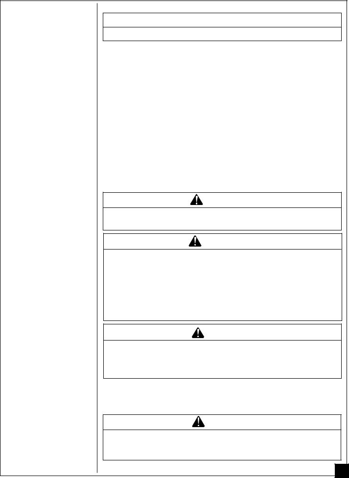
CEILING
36"
Minimum
 6" Minimum
From 

 Sides Of
Heater
Right
Left Side
Side
3" Minimum To Top Surface
Of Carpeting, Tile Or Other
Combustible Material
FLOOR
Figure 4 - Mounting Clearances As Viewed From Front of Heater
THERMOSTAT SENSING BULB
The thermostat sensing bulb is located inside the heater. Do not move this bulb during installation or operation of the heater.
INSTALLING HEATER TO WALL
Marking Screw Locations
1. Determine where you will locate heater.
 WARNING
Maintain minimum clearances shown in Figure 5. If you can, provide greater clearances from floor and joining wall.
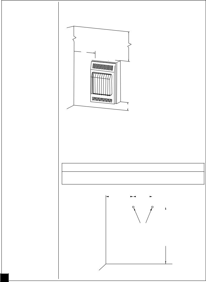
2. Mark two mounting screw locations on wall (see Figure 5).
|
|
8 7/8" |
|
|
|
7 3/4" |
|
|
|
|
|
|
|
|
|
|
|
|
|
|
|||||
|
Minimum To |
|
|
|
|
|
|
|
||||
|
Maintain 6" |
|
|
|
|
|
|
|
||||
|
|
|
|
|
|
|
||||||
|
Clearance |
|
|
|
|
|
|
|
||||
|
From Wall |
|
|
|
|
|
|
|
||||
WALL |
Mounting |
|
|
|
||||||||
20 1/4" |
||||||||||||
|
|
|
|
|
||||||||
JOINING |
Screw |
Minimum To |
||||||||||
Locations |
Maintain 3" |
|||||||||||
|
|
|
|
|
||||||||
|
|
|
|
|
|
|
|
|
Clearance |
|||
|
|
|
|
|
|
|
|
|
From Floor |
|||
FLOOR
Figure 5 - Mounting Screw Locations
103574
 Loading...