


 Loading...
Wood burning Fireplace
OWNER’S OPERATION AND INSTALLATION MANUAL
ICC-ES #ESR-2542
Model B36L-M
SAVE THIS BOOK
This book is valuable. In addition to instructing you on how to install and maintain your appliance, it also contains information that will enable you to obtain replacement parts or accessory items when needed. Keep it with your other important papers.
This fireplace is approved for use as a wood burning fireplace or for use with a vented gas log approved to ANS Z21.60, Z21.84 or RGA2-72 standards or for use with a ventfree gas log heater approved to ANS Z21.11.2 standard. A DESA Heating, LLC hood must be installed when using a vent-free log heater (see Accessories, page 18).
This wood burning fireplace complies with UL127- CAN/ULC-S610-M87 standard as a FACTORY BUILT
APPLIANCE.
FOR CANADA: The authority having jurisdiction (such as the municipal building department, fire department, etc.) should be contacted before installation to determine the need to obtain a permit.
INSTALLER: Leave this manual with the appliance. CONSUMER: Retain this manual for future reference.
For more information, visit www.desatech.com

Table of Contents
Safety................................................................... |
2 |
Operation and Maintenance............................... |
14 |
Specifications....................................................... |
3 |
Technical Service............................................... |
15 |
Fireplace Installation............................................ |
4 |
Parts................................................................... |
16 |
Venting Installation............................................... |
7 |
Replacement Parts............................................. |
18 |
Optional Gas Line Installation............................ |
13 |
Accessories........................................................ |
18 |
Safety
 WARNING: Improper installation, adjustment, alteration, service or maintenance can causeinjury,propertydamageor loss of life. Refer to this manual for assistance or additional information. Consult a qualified installer or local distributor.
IMPORTANT:Checklocalcodes before installing this fireplace.
Before beginning installation of this fireplace, read these instructions through completely.
•This DESA Heating, LLC fireplace and its components are safe when installed according to this installation manual. Unless you use DESA Heating, LLC components, which have been designed and tested for the fireplace system, you may cause a fire hazard.
•The DESA Heating, LLC warranty will be voided by and DESA Heating, LLC disclaims any responsibility for the following actions.
a.Modification of the fireplace, components, doors, air inlet system and damper control.
b.Use of any component part not manufactured or approved by DESA Heating, LLC in combination with a DESA Heating, LLC fireplace system.
Proper installation is the most important step in ensuring safe and continuous operation of fireplace. Consult the local building codes as to the particular requirements concerned with the installation of all factory built fireplaces.
 WARNING: Do not install a fireplaceinsertinthisboxunless the manufacturer's instructions with the insert specifically state thisfireplacehasbeentestedfor use with this insert.
FOR YOUR SAFETY
•Do not store or use gasoline oranyotherflammablevapors or liquids in the vicinity of this or any other appliance.
•Due to high temperatures, the appliance should be located out of traffic and away from furniture and draperies.
•Do not place clothing or other flammablematerialsonornear the appliance.
•Never leave children unattended when a fire is burning in the fireplace.
 WARNING: Use solid wood or processed solid fuel fire logs only. When processed wood fuel fire logs are used, do not poke or stir the logs while they are burning. Use only fire logs that have been evaluated for the application in fireplace and refer to fire log warnings and caution markings on packaging prior to use.
This fireplace is not intended to be used as a substitute for a furnacetoheatanentirehome.Use for supplemental heat only.
|
www.desatech.com |
115385-01B |

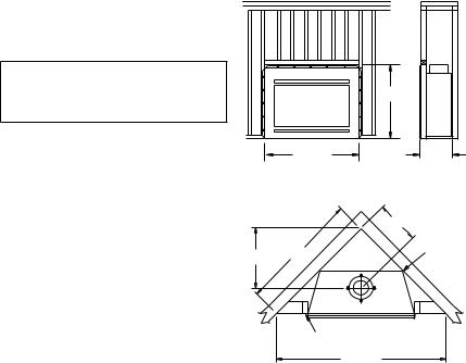
Specifications
0" TO
TOP SPACERS
0.75" AIR
SPACE BACK AND SIDES
OUTSIDE AIR (LEFT SIDE ONLY)
0" TO BOTTOM
21.125"
0.750"
37.25"
1" AIRSPACE
TO COMBUSTIBLE
MATERIAL NO COMBUSTIBLE MATERIAL ON FACE
AIR KIT |
GAS LINE |
KNOCK OUT |
KNOCK OUT |
COMBUSTIBLE
WALL BOARD
12.875"
8.125"
9.625"
NOT LESS
THAN 14" TO |
10.188" |
PERPENDICULAR
SIDEWALL
HEARTH
EXTENSION 12" 52" X 16" EACH SIDE
22.5" |
19.375" |
14.438"
14"
34.75"
38"
ROUND TOP TERMINATION
33" |
|
21.5" |
32" |
SQUARE CHASE-TOP |
|
|
|
|
|
|
|
|
|
TERMINATION |
6.75" |
36" |
1.75" |
|
|
38" |
|
|||
|
|
|
|
|
|
1" |
|
|
|
115385-01B |
www.desatech.com |
Fireplace Installation
Selecting location
To determine safest and most efficient location for fireplace, you must take into consideration the following guidelines:
1.Location must allow for proper clearances (see Figures 1 and 2).
2.Consider a location where fireplace will not be affected by drafts, air conditioning ducts, windows or doors.
3.A location that avoids cutting of joists or roof rafters will make installation easier.
4.An outside air kit is available with this fireplace (see Optional Outside Air Kit on page 7).
Minimum clearance to combustibles
Back and sides of fireplace |
3/4" minimum* |
Floor** |
0" minimum |
Perpendicular wall to opening |
14" minimum |
|
Top spacers |
|
0" minimum |
Mantel clearances |
see Mantels, page 6 |
|
Chimney outer pipe surface |
1" minimum |
|
* Not required at nailing flanges |
|
|
** See step 2 of Framing |
|
|
 WARNING: Do not pack required air spaces with insulation or other materials.
Minimum/Maximum Chimney Height
Minimum height of chimney, measured from base of fireplace to flue gas outlet of termination, is 11.5 feet for straight flue or a flue with one elbow set. Maximum distance between elbows is 2 feet. For systems with two elbow sets, minimum height is 22 feet. Maximum height of any system is 50 feet.This measurement includes fireplace, chimney sections and height of termination assembly at level of flue gas outlet (see Figure 18, page 11).
Framing
1.Frame opening for fireplace using dimensions shown in Figures 1 and 2.
2.If fireplace is to be installed directly on carpeting, tile (other than ceramic) or any combustible material other than wood flooring, fireplace must be installed upon a metal or wood panel extending full width and depth of fireplace.
3.Set fireplace directly in front of this opening and slide unit back until nailing flanges touch side framing.
4.Check level of fireplace and shim with sheet metal if necessary.
5.Before securing fireplace to prepared framing, ember protector must be placed between hearth extension (not included) and under bottom front edge of fireplace to protect against glowing embers falling through. If fireplace is to be installed on a raised platform, a Z-type ember protector (not included) must be fabricated to fit your required platform height. Ember protector should extend under fireplace a minimum of 1 1/2". Ember protector should be made of galvanized sheet metal (28 gauge minimum) to prevent corrosion.
6.Using screws or nails, secure fireplace to framing through flanges located on sides of fireplace.
|
37.625" |
38.25" |
22" |
Figure 1 - Framing Dimensions
Maintain 3/4" Clearance at
13 3/4" Sides and  Back of
Fireplace
19 1/2" 47 3/8"
3/4" Clearance Not  Required at Nailing Flanges
66 7/8"
Figure 2 - Corner Installation
www.desatech.com |
115385-01B |
Fireplace Installation
Continued
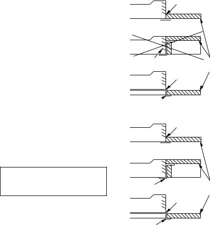
Hearth Extension
A hearth extension projecting a minimum of 16" in front of and a minimum of 8" beyond each side of fireplace opening is required to protect combustible floor construction in front of fireplace. Fabricate a hearth extension using a material which meets the following specifications: a layer of noncombustible, inorganic material having a thermal conductivity of K=0.84 BTU IN/FT, HR. F (or less) at 1" thick. For example, if material selected has a K factor of 0.25, such as glass fiber, the following formula would apply:
0.25 x 1.0" = 0.30" thickness required
0.84
Thermal conductivity "K" of materials can be obtained from manufacturer or supplier of noncombustible material. If hearth extension is to be covered, use noncombustible material such as tile, slate, brick, concrete, metal, glass, marble, stone, etc. Provide a means to prevent hearth extension from shifting and seal gap between fireplace frame and hearth extension with a noncombustible material (see Figure 3).
 WARNING:Hearthextension
is to be installed only as shown
in Figure 3.
Seal Gap
Fireplace Front
Ember Protector
NO |
|
Do Not Block Louver |
Hearth |
|
|
|
Extension |
Fireplace Front |
Seal Gap |
Elevated |
|
Ember Protector
Hearth Extension, Circulating Modes
Seal Gap
Fireplace Front
Ember Protector
Fireplace Front |
|
Raised Hearth |
|
Ember Protector |
Hearth |
|
|
|
Extension |
Fireplace Front |
Seal Gap |
Elevated |
|
Ember Protector |
|
Hearth Extension, Noncirculating Models
Figure 3 - Hearth Extension
115385-01B |
www.desatech.com |

Fireplace Installation
Continued
Mantels
A mantel may be installed if desired (see Figure 4). Woodwork such as wood trims, mantels or any other combustible material projecting from front face must not be placed within 9" of fireplace opening (and within 9" of top louver opening). Combustible materials above 9" and projecting more than 1 1/2" from fireplace must not be placed less than 12" from top opening of fireplace (NFPA STD 211, Sec. 7-3.3.3).
Mantels or any other combustible material may come up to side edge of black metal face of fireplace if projection from front face falls within limits shown in Figure 5.
|
12 1/4" Ref. |
Combustible |
|
|
|
|
Material |
6" |
|
|
Safe Zone For |
|
|
Projection of |
|
Ref. |
33° |
Combustible |
|
|
Materials |
||
|
|
|
|
|
3" Nom. |
*Note: Drawing |
|
|
|
|
Not To Scale |
12" |
|
1 1/2" |
|
Min. |
|
|
|
|
6" Max. |
|
|
|
|
|
|
|
9" |
Min. |
|
|
|
|
|
|
Min. |
|
|
|
|
Top of |
Upper Section |
|
|
Louvered |
of Circulating |
|
|
Opening |
Fireplace |
Fireplace Opening |
|
||
Figure 4 - Mantel Clearances to |
|||
|
|
Combustible Material |
|
|
|
|
FIREBOX |
Top View of Fireplace |
|
||
|
|
|
0.625" Max. |
9" |
|
SAFE ZONE |
1" |
33° |
|
|
|
|
|
|
|
 Min. 12" from Perpendicular Side Wall
Figure 5 - Side Mantel Clearance
Fan/Blower Kit assembly
Fan or blower kit is optional with this fireplace (for circulating models only). Use of blowers or fans other than those manufactured by DESA Heating, LLC voids warranty. Fan is operated by pressing rocker switch (see Figure 6) in lower right hand corner of fireplace face. Blower is operated by turning control knob (not shown).
Fan/blower kit electrical connections are made through electrical cover plate on side of fireplace a shown in Figure 6.
Rocker |
Electrical |
Electrical |
Switch |
Bushing |
Cover |
|
|
Plate |
Electrical |
Wire Nut (3x) |
Outer Wrapper |
|
(Not Supplied) |
of Fireplace |
||
Housing |
|||
|
Power Source Wiring |
||
|
|
||
|
|
(Not Supplied) |
|
|
|
To Power |
|
|
|
Source |
Electrical Cover
Plate and
Receptacle Electrical Bushing (Supplied)
Fireplace Chassis
Prewired Receptacle Ground
and Ground
Figure 6 - Fan Switch-Electrical Bushing
Wiring Instructions
1.Remove electrical cover plate with bushing from fireplace by removing 2 sheet metal screws as shown in Figure 6.
2.Slide power source wiring through electrical bushing opening and electrical cover plate and make all necessary connections.
3.Slide all wiring connections in electrical housing as shown in Figure 6.
4.Secure electrical cover plate with screws previously removed.
Note: Electrical housing and cover plate have sharp edges. Wear protective gloves.
www.desatech.com |
115385-01B |
Loading...