


 Loading...
AM-FM STEREO RECEIVER
DRA-395
OPERATING INSTRUCTIONS
MODE D’EMPLOI
|
|
|
|
|
|
|
|
|
|
|
|
|
|
OFF |
POWER |
ON |
|
|
|
|
|
|
|
|
|
|
|
|
|
|
|
RANDOM |
6 |
7 |
8 |
|
9 |
|
|
|
|
|
|
|
|
|
|
|
|
|
REPEAT |
DISC SKIP |
3 |
2 |
CD |
1 |
|
|
|
|
|
|
|
|
|
|
|
|
|
|
A / B |
4REC |
3 |
|
2 |
|
|
|
|
|
|
|
|
|
|
|
|
|
ON |
|
|
|
|
|
|
|
|
|
|
|
|
|
|
|
|
|
|
MAIN |
6 |
7 |
0 TAPE |
1 |
|
|
|
|
|
|
|
|
|
|
|
|
|
|
OFF |
|
|
|
|
|
|
|
|
|
|
|
|
|
|
|
|
|
|
ZONE 2 |
ZONE 3 MULTI ROOM |
||||
|
|
|
|
|
|
|
|
|
|
|
|
|
ON |
• |
ON |
• |
|
|
|
|
|
|
|
|
|
|
|
|
|
|
|
|
VOLUME |
|
VOLUME |
|
|
B PRECISION AUDIO COMPONENT / STEREO RECEIVER DRA-395 |
|
|
|
|
|
|
|
|
MASTER VOLUME |
OFF |
ª |
OFF |
ª |
|
|
|||
|
|
|
|
|
|
|
|
|
TUNER |
PHONO |
V. AUX |
VCR |
DVD / VDP |
|||||
|
CD |
PHONO |
|
|
|
|
|
|
|
|
|
|
|
|
|
|
|
|
|
|
|
|
|
|
|
|
|
|
VOLUME LEVEL |
|
|
|
CD |
|
PHONO |
DVD / VDP |
|
|
|
REMOTE |
|
|
|
|
|
|
|
|
|
|
|
|
|
|
|
|
|
|
SENSOR |
Multi Room |
|
|
|
|
|
|
|
|
• |
|
|
|
|
|
|
|
TUNER |
DVD / VDP |
|
|
|
|
|
|
|
|
PRESET |
CDR / TAPE |
|
CD |
|
VCR |
||
|
|
|
Music Entertainment System |
|
|
|
|
|
|
|
|
|
|
|
|
|
|
|
|
|
|
|
|
|
|
|
|
|
|
|
|
ª |
|
|
|
|
|
|
|
ON / STANDBY |
ZONE 2 |
ZONE 3 |
|
|
|
|
|
|
|
|
A SPEAKER B |
TUNER |
CDR / TAPE |
V. AUX |
||
|
|
|
|
|
|
|
|
|
|
|
|
|
||||||
CDR / TAPE |
VCR |
V.AUX |
|
|
|
|
|
|
|
|
|
|
|
|
|
|
|
|
|
|
|
|
|
|
|
|
|
|
|
|
|
DIMMER |
CH VOL |
|
SHIFT |
|
|
|
|
SHIFT |
DOWN |
UP |
BAND |
MODE |
MEMORY |
DOWN |
UP |
VIDEO SELECT DIMMER |
STATUS |
|
|
|
|
|
|
|
|
|
|
PRESET |
|
|
|
TUNING |
|
|
|
|
STATUS |
|
• |
|
|
• |
|
|
|
|
|
|
|
|
|
|
|
|
|
|
|
|
|
|
|
|
|
|
|
|
|
|
|
|
|
|
|
|
|
|
• |
PRESET |
|
MASTER VOL |
|
|
|
|
|
|
|
|
|
|
|
|
|
|
VIDEO SELECT |
|
ª |
MUTING |
|
ª |
|
|
|
|
|
|
|
|
|
|
|
TONE |
SELECT |
TREBLE |
ª |
|
|
|
|
ON / STANDBY |
|
PHONES |
SPEAKER |
|
REC / MULTI |
|
|
|
|
DEFEAT |
|
|
|
|
|
|||
|
|
|
|
|
|
|
|
|
|
|
|
|
||||||
|
|
A |
B |
REC OUT |
ZONE 2 |
ZONE 3 |
SELECT |
LOUDNESS |
|
|
|
UP |
|
B |
|
|
||
|
|
|
|
|
|
|
|
|
|
|
|
|
|
|
|
|||
|
|
|
|
|
|
|
|
|
|
|
|
|
|
REMOTE CONTROL UNIT RC-894 |
|
|||
|
|
|
|
|
|
|
|
|
|
|
|
DOWN |
|
|
|
|
|
|
|
|
|
|
|
|
|
|
|
|
|
CH VOL |
|
BASS |
|
|
|
|
|
FOR ENGLISH READERS |
PAGE 02 ~ PAGE 26 |
2We greatly appreciate your purchase of this unit.
2To be sure you take maximum advantage of all the features this unit has to offer, read these instructions carefully and use the set properly. Be sure to keep this manual for future reference should any questions or problems arise.
“SERIAL NO.
PLEASE RECORD UNIT SERIAL NUMBER ATTACHED TO THE REAR OF THE CABINET FOR FUTURE REFERENCE”
POUR LES LECTEURS FRANCAIS PAGE 2, 27 ~ PAGE 49
2Nous vous remercions pour l’achat de cet appareil.
2Pour être sûr de profiter au maximum de toutes les caractéristiques qu’offre cet appareil, lire avec soin ces instructions et bien utiliser l’appareil. Toujours conserver ce mode d’emploi pour s’y référer ultérieurement en cas de question ou de problème.
“NO. DE SERIE
PRIERE DE NOTER LE NUMERO DE SERIE DE L’APPAREIL INSCRIT A L’ARRIERE DU COFFRET DE FAÇON A POUVOIR LE CONSULTER EN CAS DE PROBLEME.”
ENGLISH FRANCAIS
2SAFETY PRECAUTIONS
CAUTION
RISK OF ELECTRIC SHOCK
DO NOT OPEN
CAUTION: REDUCE THE RISK OF ELECTRIC SHOCK, DO NOT REMOVE COVER (OR BACK). NO USER-SERVICEABLE PARTS INSIDE. REFER SERVICING TO QUALIFIED SERVICE PERSONNEL.
The lightning flash with arrowhead symbol, within an equilateral triangle, is intended to alert the user to the presence of uninsulated “dangerous voltage” within the product’s enclosure that may be of sufficient magnitude to constitute a risk of electric shock to persons.
The exclamation point within an equilateral triangle is intended to alert the user to the presence of important operating and maintenance (servicing) instructions in the literature accompanying the appliance.
WARNING: TO REDUCE THE RISK OF FIRE OR ELECTRIC SHOCK, DO NOT EXPOSE THIS APPLIANCE TO RAIN OR MOISTURE.
CAUTION
TO PREVENT ELECTRIC SHOCK, MATCH WIDE BLADE OF
PLUG TO WIDE SLOT, FULLY INSERT.
ATTENTION
POUR ÉVITER LES CHOCS ÉLECTRIQUES, INTERODUIRE LA
LAME LA PLUS LARGE DE LA FICHE DANS LA BORNE
CORRESPONDANTE DE LA PRISE ET POUSSER JUSQU’ AU
FOND.
This device complies with Part 15 of the FCC Rules. Operation is subject to the following two conditions: (1) This device may not cause harmful interference, and (2) this device must accept any interference received, including interference that may cause undesired operation.
This Class B digital apparatus meets all requirements of the Canadian Interference-Causing Equipment Regulations.
Cet appareil numérique de la classe B respecte toutes les exigences du Règlement sur le matériel brouilleur du Canada.
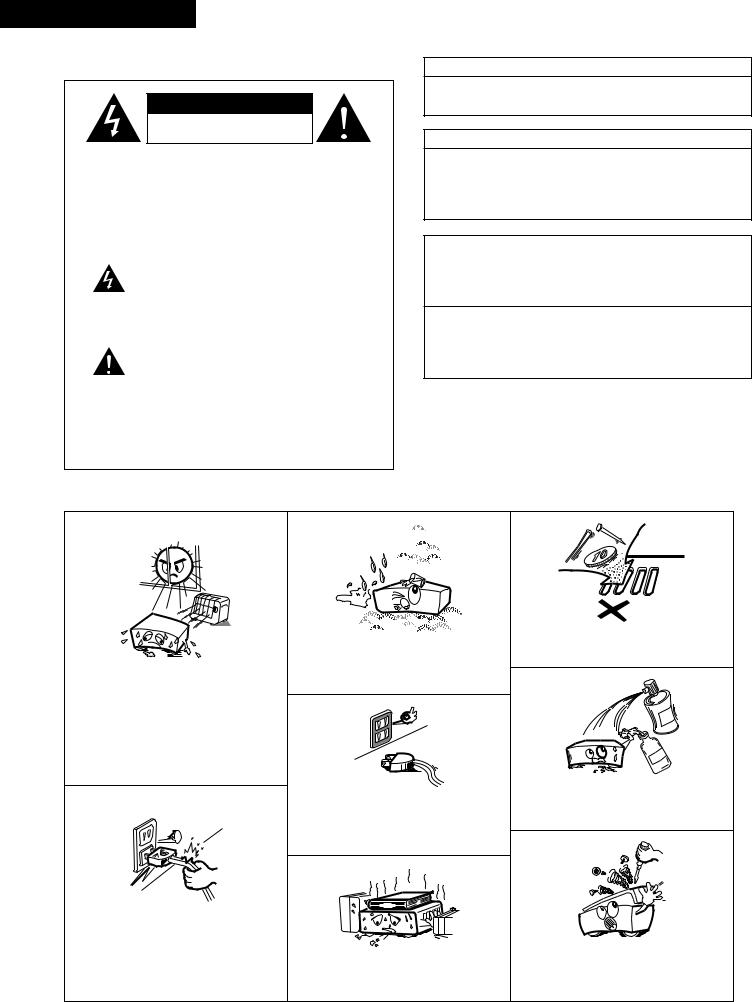
2NOTE ON USE / OBSERVATIONS RELATIVES A L’UTILISATION
•Avoid high temperatures.
Allow for sufficient heat dispersion when installed on a rack.
•Eviter des températures élevées
Tenir compte d’une dispersion de chaleur suffisante lors de l’installation sur une étagère.
•Handle the power cord carefully.
Hold the plug when unplugging the cord.
•Manipuler le cordon d’alimentation avec précaution.
Tenir la prise lors du débranchement du cordon.
•Keep the set free from moisture, water, and dust.
•Protéger l’appareil contre l’humidité, l’eau et la poussière.
•Unplug the power cord when not using the set for long periods of time.
•Débrancher le cordon d’alimentation lorsque l’appareil n’est pas utilisé pendant de longues périodes.
*(For sets with ventilation holes)
•Do not obstruct the ventilation holes.
•Ne pas obstruer les trous d’aération.
•Do not let foreign objects in the set.
•Ne pas laisser des objets étrangers dans l’appareil.
•Do not let insecticides, benzene, and thinner come in contact with the set.
•Ne pas mettre en contact des insecticides, du benzène et un diluant avec l’appareil.
•Never disassemble or modify the set in any way.
•Ne jamais démonter ou modifier l’appareil d’une manière ou d’une autre.
2
SAFETY INSTRUCTIONS
1.Read Instructions – All the safety and operating instructions should be read before the appliance is operated.
2.Retain Instructions – The safety and operating instructions should be retained for future reference.
3.Heed Warnings – All warnings on the appliance and in the operating instructions should be adhered to.
4.Follow Instructions – All operating and use instructions should be followed.
5.Water and Moisture – The appliance should not be used near water – for example, near a bathtub, washbowl, kitchen sink, laundry tub, in a wet basement, or near a swimming pool, and the like.
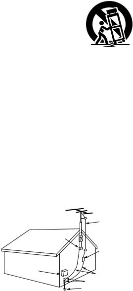
6.Carts and Stands – The appliance should be used only with a cart or stand that is recommended by the manufacturer.
6A. An appliance and cart combination should be moved with care. Quick stops, excessive force, and uneven surfaces may cause the appliance and cart
combination to overturn.
7.Wall or Ceiling Mounting – The appliance should be mounted to a wall or ceiling only as recommended by the manufacturer.
8.Ventilation – The appliance should be situated so that its location or position does not interfere with its proper ventilation. For example, the appliance should not be situated on a bed, sofa, rug, or similar surface that may block the ventilation openings; or, placed in a built-in installation, such as a bookcase or cabinet that may impede the flow of air through the ventilation openings.
9.Heat – The appliance should be situated away from heat sources such as radiators, heat registers, stoves, or other appliances (including amplifiers) that produce heat.
10.Power Sources – The appliance should be connected to a power supply only of the type described in the operating instructions or as marked on the appliance.
11.Grounding or Polarization – Precautions should be taken so that the grounding or polarization means of an appliance is not defeated.
FIGURE A
EXAMPLE OF ANTENNA GROUNDING
AS PER NATIONAL
ELECTRICAL CODE ANTENNA
LEAD IN
WIRE
GROUND
CLAMP
ANTENNA DISCHARGE UNIT
(NEC SECTION 810-20)
ELECTRIC
SERVICE
EQUIPMENT
GROUNDING CONDUCTORS (NEC SECTION 810-21)
GROUND CLAMPS
POWER SERVICE GROUNDING ELECTRODE SYSTEM
(NEC ART 250, PART H)
NEC - NATIONAL ELECTRICAL CODE
12.Power-Cord Protection – Power-supply cords should be routed so that they are not likely to be walked on or pinched by items placed upon or against them, paying particular attention to cords at plugs, convenience receptacles, and the point where they exit from the appliance.
14.Cleaning – The appliance should be cleaned only as recommended by the manufacturer.
15.Power Lines – An outdoor antenna should be located away from power lines.
16.Outdoor Antenna Grounding – If an outside antenna is connected to the receiver, be sure the antenna system is grounded so as to provide some protection against voltage surges and built-up static charges. Article 810 of the National Electrical Code, ANSI/NFPA 70, provides information with regard to proper grounding of the mast and supporting structure, grounding of the lead-in wire to an antenna-discharge unit, size of grounding conductors, location of antenna-discharge unit, connection to grounding electrodes, and requirements for the grounding electrode. See Figure A.
17.Nonuse Periods – The power cord of the appliance should be unplugged from the outlet when left unused for a long period of time.
18.Object and Liquid Entry – Care should be taken so that objects do not fall and liquids are not spilled into the enclosure through openings.
19.Damage Requiring Service – The appliance should be serviced by qualified service personnel when:
A.The power-supply cord or the plug has been damaged; or
B.Objects have fallen, or liquid has been spilled into the appliance; or
C.The appliance has been exposed to rain; or
D.The appliance does not appear to operate normally or exhibits a marked change in performance; or
E.The appliance has been dropped, or the enclosure damaged.
20.Servicing – The user should not attempt to service the appliance beyond that described in the operating instructions. All other servicing should be referred to qualified service personnel.
3
ENGLISH
2INTRODUCTION
Thank you for choosing the DENON AM-FM Stereo receiver. This remarkable component has been engineered to provide outstanding high fidelity reproduction of your favorite music sources.
As this product is provided with an immense array of features, we recommend that before you begin hookup and operation that you review the contents of this manual before proceeding.
TABLE OF CONTENTS
z Before Using ................................................................................ |
4 |
x Cautions on Installation ................................................................ |
5 |
c Cautions on Handling ................................................................... |
5 |
v Features ....................................................................................... |
5 |
b Connections ........................................................................... |
6~10 |
n Part Names and Functions ......................................................... |
10 |
m Remote Control Unit ............................................................ |
11, 12 |
, Operations ........................................................................... |
13~20 |
. Listening to the Radio .......................................................... |
21~23 |
⁄0Initialization of the Microprocessor ............................................ |
24 |
⁄1Last function memory ................................................................ |
24 |
⁄2Troubleshooting.......................................................................... |
25 |
⁄3Specifications ............................................................................. |
26 |
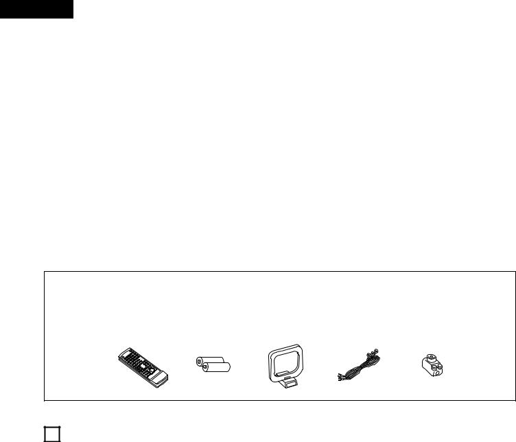
2ACCESSORIES
Check that the following parts are included in addition to the main unit:
q Operating instructions .............................................................. |
1 |
w Warranty ................................................................................... |
1 |
e Service station list..................................................................... |
1 |
r Remote control unit (RC-894) ................................................... |
1 |
t Batteries (R03/AAA) |
.................................................................2 |
y AM loop antenna...................................................................... |
1 |
u FM indoor antenna................................................................... |
1 |
i FM antenna adapter................................................................. |
1 |
r |
t |
y |
u |
i |
(RC-894)
1 BEFORE USING
Pay attention to the following before using this unit:
•Moving the set
To prevent short circuits or damaged wires in the connection cords, always unplug the power cord and disconnect the connection cords between all other audio components when moving the set.
•Before turning the power operation switch on
Check once again that all connections are proper and that there are not problems with the connection cords. Always set the power operation switch to the standby position before connecting and disconnecting connection cords.
•Store this instructions in a safe place.
After reading, store this instructions along with the warranty in a safe place.
•Note that the illustrations in this instructions may differ from the actual set for explanation purposes.
4
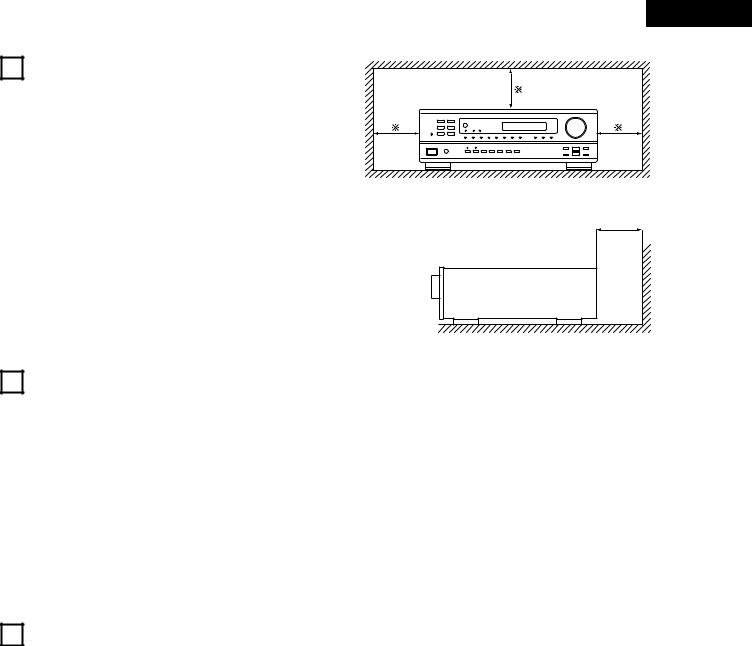
2 CAUTIONS ON INSTALLATION
Noise or disturbance of the picture may be generated if this unit or any other electronic equipment using microprocessors is used near a tuner or TV.
If this happens, take the following steps:
•Install this unit as far as possible from the tuner or TV.
•Set the antenna wires from the tuner or TV away from this unit’s power cord and input/output connection cords.
•Noise or disturbance tends to occur particularly when using indoor antennas or 300 Ω /ohms feeder wires. We recommend using outdoor antennas and 75 Ω /ohms coaxial cables.
For heat dispersal, leave at least 0.3 ft (10 cm) of space between the top, back and sides of this unit and the wall or other components.
ENGLISH
0.3 ft (10 cm) or more |
B |
0.3 ft (10 cm) or more
Wall
3CAUTIONS ON HANDLING
•Switching the input function when input jacks are not connected
A clicking noise may be produced if the input function is switched when nothing is connected to the input jacks. If this happens, either turn down the VOLUME control or connect components to the input jacks.
•Muting of PRE OUT jacks
The PRE OUT jacks include a muting circuit. Because of this, the output signals are greatly reduced for several seconds after the power operation switch is turned on.
If the volume is turned up during this time, the output will be very high after the muting circuit stops functioning. Always wait until the muting circuit turns off before adjusting the volume.
4FEATURES
1.Multi Room Music Entertainment System
Multi Source Function:
This unit’s Multi Source function lets you select different audio or video sources for viewing or listening Different sources can thus be enjoyed in the main room and the subroom simultaneously. Playback of single audio/video source that differs from the Main Room is permitted in the two rooms, sub room (ZONE 2) and sub room (ZONE 3). The signals output to ZONE 2 and ZONE 3 can each be switched on and off independently. Independent volume control is also permitted. This novel feature gives you considerable flexibility when setting up and enjoying your system with this unit. The output level, adjustable by the remote commander, is as much as 1V, enough to operate the optional power amplifier placed in a subroom.
2.Powerful, Versatile Amplifier
High-Quality Power Amplifier:
High-speed, high-power transistors employed in a rational circuit configuration reflect DENON’S advanced amplifier technology and ensure a very hefty, clean power output.
•Whenever the power operation switch is in the STANDBY state, the apparatus is still connected on some AC line voltages.
Please be sure to unplug the cord when you leave home for, say, a vacation.
3.Signal Level Divided Construction (SLDC)
The circuits handling low-level and high-level signals have been divided into separate blocks to ensure that influences from these signals on each other are held to an absolute minimum. This chassis design in this unit is called the Signal Level Divided Construction (SLDC). Signals for output are cleaner than before, allowing them to be reproduced with even greater fidelity and clarity.
4.Remote Control Functions
The Remote Control (RC-894) commands not only the receiver but can also operate the main functions of a DENON CD player and a cassette deck.
External remote control equipment, such as DENON's RC-616 and RC-617, can be connected to this unit. By connecting such equipment and using the RC-894 remote control from a sub room (ZONE 2 or 3) allows the sub room output to be switched on and off, the selection of sub room source, volume adjustment, and the recalling of preset radio stations from the sub room.
5
ENGLISH
5 |
CONNECTIONS |
|
|
|
|
|
|
• |
Do not plug in the power cord until all connections have been |
• |
Note that binding pin plug cords together with power cords or |
|
completed. |
|
placing them near a power transformer will result in generating |
• |
Be sure to connect the left and right channels properly (left |
|
hum or other noise. |
|
with left, right with right). |
• |
If hum or other noise is produced when the ground wire is |
• |
Insert the plugs securely. Incomplete connections will result in |
|
connected, disconnect it. |
|
the generation of noise. |
• Noise or humming may be generated if a connected |
|
• |
Use the AC OUTLETS for audio equipment only. Do not use |
|
component is used independently without turning the power of |
|
them for hair driers, etc. |
|
this unit on. If this happens, turn on the power of the this unit. |
|
|
|
|
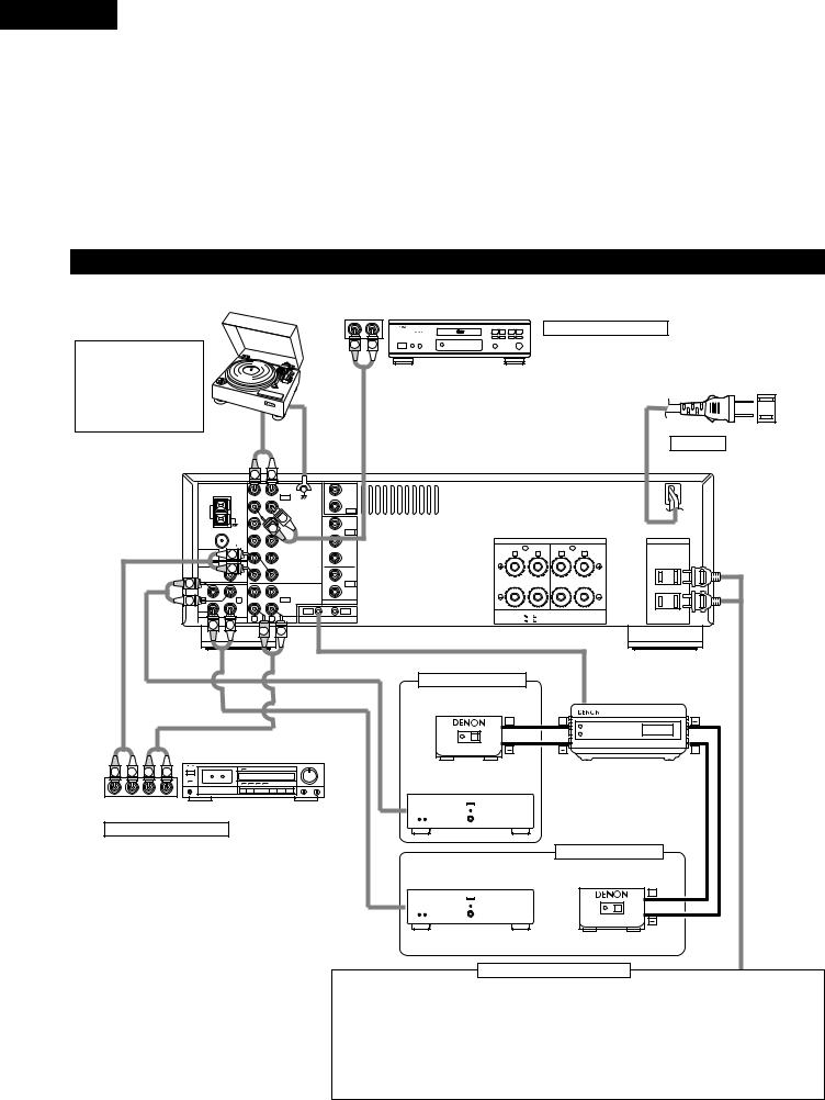
Connecting the audio components
|
|
|
|
|
|
|
OUTPUT |
|
Turntable (MM cartridge) |
|
|
|
R |
L |
|||
|
|
|
|
|
||||
NOTE: |
|
|
|
|
|
|
R |
L |
|
|
|
|
|
|
|
|
|
This unit cannot be used |
|
|
|
|
|
|
||
with |
MC |
cartridges |
|
|
|
|
|
OUT |
directly. Use a separate |
|
|
|
|
|
|||
|
|
|
|
|
|
|||
head amplifier or step- |
|
|
|
|
|
LINE |
||
up transformer. |
|
|
|
|
|
|||
|
|
|
|
|
|
|||
|
|
|
|
|
|
Ground |
|
|
|
|
|
|
|
|
wire |
|
|
|
|
|
|
R |
L |
|
|
|
|
|
|
|
|
PHONO |
|
ZONE 2 |
|
|
|
|
|
|
IN |
|
MULTI |
|
|
|
|
|
|
SIGNAL |
ROOM |
|
|
|
|
|
|
|
CD |
|
||
|
|
|
LOOP |
AM |
GND |
ZONE 3 |
|
|
|
|
|
|
|
OUT |
|
||
|
|
|
ANT. |
|
L |
|
|
|
|
|
|
|
|
|
DVD/ |
|
|
|
|
|
|
|
R |
|
VDP |
|
|
|
|
|
|
|
IN |
|
|
|
|
|
|
FM |
|
|
|
|
|
|
|
|
|
|
|
|
|
|
|
|
|
COAX. |
AUX |
|
V. AUX |
|
|
|
|
|
75 |
|
|
|
|
|
|
|
ANTENNA |
L |
|
|
|
|
|
|
|
TERMINALS |
VCR |
|
VCR |
|
|
|
|
|
|
|
|
|||
|
|
|
PRE OUT |
R |
|
|
|
|
|
|
|
SUB |
CDR/ |
|
MONITOR |
|
|
|
|
|
WOOFER |
|
TAPE |
|
|
|
|
|
R |
|
|
|
|
||
|
|
|
ZONE |
|
|
OUT |
|
|
|
|
|
|
VCR |
|
VCR |
|
|
|
|
|
|
2 |
|
|
||
|
|
L |
|
OUT |
|
|
|
|
|
|
R |
L |
|
VIDEO |
|
||
|
|
|
|
ZONE |
CDR/ |
IN |
OUT |
|
|
|
|
OUT |
3 |
TAPE |
|
||
MULTI ROOM |
R |
L AUDIO ROOM TO ROOM (REMOTE CONTROL) |
 R
R  L
L 

R L
OUT |
LINE IN |
|
LINE |
||
|
Tape deck
CD player
Connecting a CD player
Connect the CD player’s analog output jacks (ANALOG
OUTPUT) to this unit’s CD jacks using pin plug cords.
AC CORD
AC 120 V, 60 Hz
|
SPEAKER SYSTEMS |
|
AC OUTLETS |
|
B |
|
|
A |
AC 120V 60Hz |
R |
L |
R |
L |
SWITCHED |
|
|
|
|
TOTAL 120W(1A.) MAX. |
SPEAKER IMPEDANCE |
|
|
|
|
A OR B / 4 |
16 |
|
|
|
A + B / 8 |
16 |
|
|
|
|
AUX OUT |
|
||
Sub room (ZONE 2) |
|
|
|
RC-616 (Sold Separately) |
RC-617 (Sold Separately) |
|
|
|
Infrared retransmitter |
|
|
|
|
|
Infrared sensor |
|
|
|
|
+ |
|
+ |
|
|
|
|
|
|
+ |
R |
L |
R |
L |
R L R L
OUTPUT INPUT
Connecting a tape deck
Connections for recording:
Connect the tape deck’s recording input jacks (LINE IN or REC) to this unit’s tape recording (OUT) jacks using pin plug cords.
Connections for playback:
Connect the tape deck’s playback output jacks (LINE OUT or PB) to this unit’s tape playback (IN) jacks using pin plug cords.
|
|
OUTPUT INPUT |
INPUT |
|
Power amplifier |
|
|
|
|
Sub room (ZONE 3) |
|
INPUT |
Power amplifier |
RC-617 (Sold Separately) |
|
Infrared sensor |
|
||
|
|
||
+
OUTPUT
Connecting the AC OUTLETS
AC OUTLETS
•SWITCHED (total capacity – 120 W (1 A.)
The power to this outlet is turned on and off in conjunction with the POWER operation switch on the main unit, and when the power is switched between on and standby from the remote control unit.
No power is supplied from these outlets when this unit’s power is at standby. Never connect equipment whose total capacity is above 120 W (1 A.)
NOTE:
Use the AC OUTLETS for audio equipment only. Do not use them for hair driers, etc.
6
ENGLISH
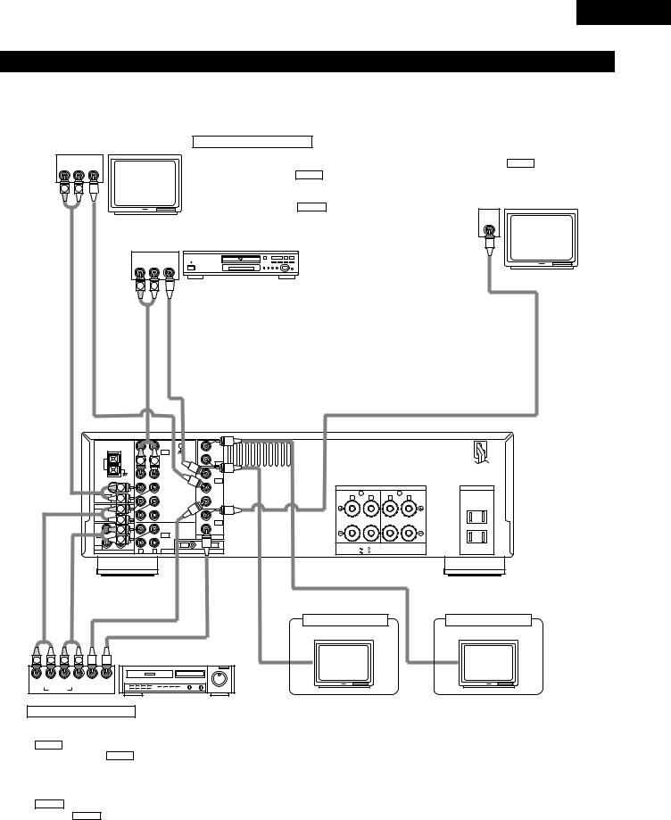
Connecting the video equipments
•To connect the video signal, connect using a 75 Ω /ohms video signal cable cord. Using an improper cable can result in a drop in sound quality.
•When making connections, also refer to the operating instructions of the other components.
|
|
TV or DBS tuner |
Connecting a TV/DBS tuner |
|
MONITOR OUT |
||
|
|
TV/DBS |
|
|
• Connect the TV’s video input jack (VIDEO |
||
AUDIO |
VIDEO |
|
|
|
|||
|
• Connect the TV’s or DBS tuner’s video output jack |
INPUT) to the VIDEO MONITOR OUT jack |
|||||
R |
L |
OUT |
|
||||
|
OUT |
|
|
|
|
|
|
|
|
|
|
(VIDEO OUTPUT) to the |
VIDEO |
(yellow) V.AUX IN jack |
using a 75 Ω /ohms video coaxial pin plug |
R |
L |
|
|
using a 75 Ω /ohms video coaxial pin plug cord. |
cord. |
||
|
|
|
|
• Connect the TV’s or DBS tuner’s audio output jacks |
Monitor TV |
||
|
|
|
|
(AUDIO OUTPUT) to the |
AUDIO |
V.AUX IN jacks using |
|
|
|
|
|
VIDEO |
|||
AUDIOOUT |
|
|
|
pin plug cords. |
|
|
|
|
VIDEOOUT |
|
|
|
IN |
||
|
|
DVD player or LD player (VDP) |
|
|
|
||
|
|
|
|
|
|
|
|
|
|
AUDIO |
VIDEO |
B |
|
|
|
|
|
OUT |
|
|
|
|
|
|
|
OUT |
|
|
|
|
|
|
|
R L |
|
|
|
|
|
R |
L |
VIDEO IN |
|
|
Connecting a DVD player or a video disc player VDP |
|
||||
OUT |
OUT |
• Connect the DVD player’s (video disc player’s) video output jack (VIDEO OUTPUT) to |
|||||
the |
|
(yellow) DVD/VDP IN jack using a 75 Ω /ohms video coaxial pin plug cord. |
|||||
VIDEO |
|||||||
AUDIO |
VIDEO |
• Connect the DVD player’s (video disc player’s) analog audio output jacks (ANALOG |
|||||
AUDIO OUTPUT) to the |
|
DVD/VDP IN jacks using pin plug cords. |
|||||
AUDIO |
|||||||
|
|
|
|
|
|
|
PHONO |
|
ZONE 2 |
|
|
|
|
|
|
|
|
|
|
|
|
IN |
|
MULTI |
|
|
|
|
|
|
|
|
|
|
|
|
SIGNAL |
ROOM |
|
|
|
|
|
|
|
|
|
|
|
|
|
|
|
|
|
|
|
||
|
|
LOOP |
AM |
R |
L |
CD |
GND |
ZONE 3 |
|
|
|
|
|
|
|
|
ANT. |
|
|
|
|
OUT |
|
|
|
|
|
||
|
|
|
|
|
|
|
DVD/ VDP |
|
DVD/ |
|
|
|
|
|
|
|
|
|
|
|
|
|
VDP |
|
|
|
|
|
|
|
|
|
|
|
|
|
|
|
|
|
|
|
|
|
|
|
|
FM |
|
|
|
|
|
IN |
|
|
|
|
|
|
|
|
|
|
|
|
|
|
|
|
|
|
|
|
|
|
|
RCOAX. |
|
|
V. AUX |
|
V. AUX |
|
SPEAKER SYSTEMS |
|
AC OUTLETS |
||
|
|
|
75 |
|
|
|
|
|
|
B |
|
|
A |
AC 120V 60Hz |
|
|
ANTENNA |
L |
|
|
|
VCR |
|
VCR |
R |
L |
R |
L |
SWITCHED |
|
|
TERMINALS |
|
|
|
|
|
|
|
|
|
TOTAL 120W(1A.) MAX. |
||
|
|
PRE OUT |
R |
|
|
|
|
|
|
|
|
|
|
|
|
|
SUB |
|
|
|
CDR/ |
|
|
|
|
|
|
|
|
|
|
|
|
|
|
|
MONITOR |
|
|
|
|
|
||
|
|
WOOFER |
L |
|
|
|
TAPE |
|
|
|
|
|
|
|
|
|
|
|
|
|
OUT |
|
|
|
|
|
|||
|
|
|
R 2ZONE |
|
|
|
|
|
|
|
|
|
||
|
|
|
|
|
VCR |
|
VCR |
|
|
|
|
|
||
|
|
R |
L |
L |
|
|
OUT |
|
VIDEO |
|
|
|
|
|
|
|
|
ZONE |
|
|
CDR/ |
|
|
|
|
|
|
||
|
IN |
|
|
|
|
|
|
|
|
|
|
|||
|
OUT |
|
3 |
|
|
TAPE |
IN |
OUT |
SPEAKER IMPEDANCE |
|
|
|
||
|
|
|
R |
L |
|
|
|
A OR B / 4 |
16 |
|
|
|
||
|
MULTI ROOM |
|
AUDIO |
ROOM TO ROOM (REMOTE CONTROL) |
|
|
|
|||||||
|
|
A + B / 8 |
16 |
|
|
|
||||||||
AUDIO OUT |
AUDIO |
|
VIDEO OUT |
|
|
|
|
|
|
|
||||
|
|
|
|
VIDEO IN |
IN |
Sub room (ZONE 3) |
IN |
Sub room (ZONE 2) |
|
|
|
|
VIDEO |
Monitor TV |
VIDEO |
Monitor TV |
|
|
|
|
|
|
||||
|
|
|
|
|
|
|
||
R |
L |
R |
L |
Video deck |
|
|
|
|
R |
L |
R |
L |
OUT IN |
|
|
|
|
|
OUT |
|
IN |
VIDEO |
|
|
|
|
|
AUDIO |
|
|
|
|
|
||
Connecting a video decks
Video input/output connections:
• Connect the video deck’s video output jack (VIDEO OUT) to the VIDEO (yellow) VCR IN jack, and the video deck’s video input jack (VIDEO IN) to the VIDEO (yellow) VCR OUT jack using 75 Ω /ohms video coaxial pin plug cords.
Connecting the audio output jacks
•Connect the video deck audio output jacks (AUDIO OUT) to the AUDIO VCR IN jacks, and the video deck’s audio input jacks (AUDIO
IN) to the AUDIO VCR OUT jacks using pin plug cords.
7
ENGLISH
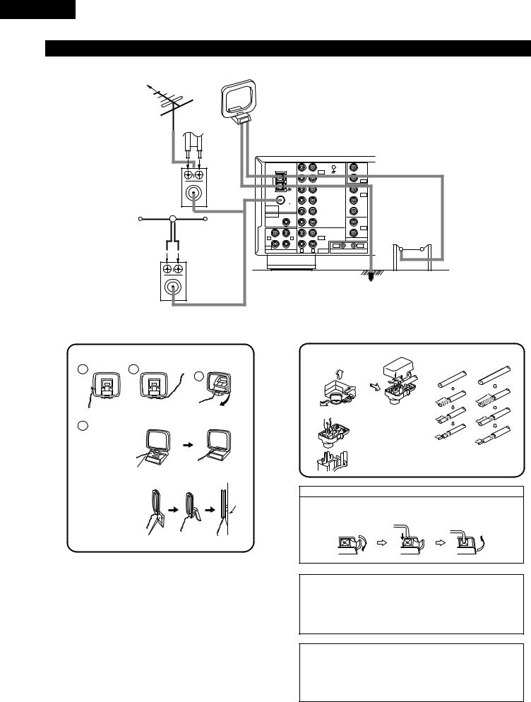
Connecting the antenna terminals
DIRECTION OF |
FM ANTENNA |
AM LOOP |
|
BROADCASTING |
ANTENNA |
||
|
|||
STATION |
|
(An Accessory) |
75 Ω /ohms |
|
FEEDER |
|
|
|
|
|
|
|
COAXIAL |
|
CABLE |
|
|
|
|
|
|
|
CABLE |
|
|
|
|
|
|
|
|
|
|
|
|
|
|
|
PHONO |
|
ZONE 2 |
|
|
|
|
|
|
|
IN |
|
MULTI |
|
|
|
|
|
|
|
SIGNAL |
ROOM |
|
|
|
|
|
|
|
|
CD |
|
||
|
|
LOOP |
AM |
|
|
GND |
ZONE 3 |
|
|
|
|
|
|
|
|
OUT |
|
||
|
|
ANT. |
|
|
|
|
|
|
|
|
|
|
|
|
|
DVD/ VDP |
|
DVD/ |
|
|
|
|
|
|
|
|
VDP |
|
|
|
|
|
|
|
|
|
|
|
|
|
|
|
FM |
|
|
|
|
IN |
|
|
|
|
|
|
|
|
|
|
|
|
|
|
COAX. |
|
|
V. AUX |
|
V. AUX |
|
|
|
|
75 |
|
|
|
|
|
|
|
|
ANTENNA |
|
|
|
|
|
|
|
|
|
TERMINALS |
|
|
|
VCR |
|
VCR |
|
|
|
PRE OUT |
|
|
|
|
|
|
|
|
|
SUB |
|
|
|
CDR/ |
|
MONITOR |
|
|
|
WOOFER |
|
|
|
TAPE |
|
AM OUTDOOR |
|
FM INDOOR ANTENNA |
300 Ω /ohms |
ZONE |
|
|
VCR |
|
OUT |
||
(An Accessory) |
|
R |
L |
|
|
|
VCR |
ANTENNA |
|
|
|
|
OUT |
|
VIDEO |
||||
|
|
|
2 |
|
|
|
|
|
|
|
|
|
ZONE |
|
|
CDR/ |
IN |
OUT |
|
|
|
OUT |
3 |
|
|
TAPE |
|
||
|
|
MULTI ROOM |
R |
L |
AUDIO |
ROOM TO ROOM (REMOTE CONTROL) |
|
||
FM ANTENNA |
300 Ω |
/ohms |
|
|
|
|
|
|
|
TERMINAL |
|
|
|
|
|
|
|
||
ADAPTER |
|
|
|
|
|
|
|
|
|
(An Accessory) |
|
|
|
|
|
|
|
GROUND |
|
AM loop antenna assembly
Connect to the AM antenna terminals.
1 |
2 |
Remove the vinyl tie and take out the
connection line.
4
a.With the antenna on top any stable
surface
Mount
b.With the antenna attach to a wall.
3
Bend in the reverse direction.
Installation hole Mount on wall, etc.
FM antenna adapter assembly
Open the Cover |
75 Ω /ohms COAXIAL CABLE |
|||||
|
|
|
|
|
||
|
PULL |
SHUT |
|
|
|
|
|
|
|
|
|
|
|
PULL |
|
4 |
|
|
m |
|
|
|
|
m |
|||
|
CLAMP |
|
m |
|
|
|
|
1 |
m |
|
9 |
||
|
1 |
|
||||
|
|
|
|
|||
ANTENNA ADAPTER |
CLAMP |
|
|
|
|
|
|
m |
|
|
m |
||
|
|
m |
|
m |
||
|
|
9 |
|
|
||
|
|
|
|
4 |
|
|
|
|
|
|
1 |
|
|
|
|
|
m |
|
|
|
|
|
m |
|
m |
||
|
|
5 |
|
|
||
|
|
|
|
m |
|
|
|
REMOVE |
|
|
5 |
|
|
|
|
|
|
|
|
|
|
|
|
3C-2V |
|
|
5C-2V |
CLAMP
Connection of AM antennas
1. Push the lever. |
2. Insert the |
3. Return the lever. |
||||
|
conductor. |
|
|
|
|
|
|
|
|
|
|
|
|
|
|
|
|
|
|
|
|
|
|
|
|
|
|
|
|
|
|
|
|
|
|
|
|
|
|
|
|
Note to CATV system installer:
This reminder is provided to call the CATV system installer’s attention to Article 820-40 of the NEC which provides guidelines for proper grounding and, in particular, specifies that the cable ground shall be connected to the grounding system of the building, as close to the point of cable entry as practical.
NOTES:
•Do not connect two FM antennas simultaneously.
•Even if an external AM antenna is used, do not disconnect AM loop antenna.
•Make sure AM loop antenna lead terminals do not touch metal parts of the panel.
8
ENGLISH
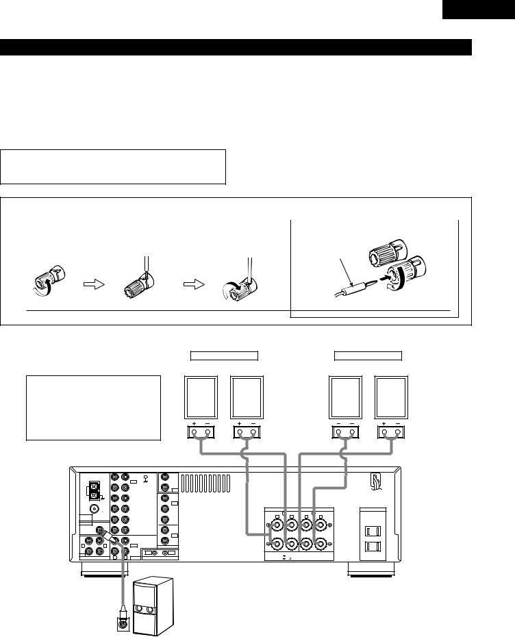
Speaker system connections
•Connect the speaker terminals with the speakers making sure that like polarities are matched (< with <, > with >). Mismatching of polarities will result in weak central sound, unclear orientation of the various instruments, and the sense of direction of the stereo being impaired.
•When making connections, take care that none of the individual conductors of the speaker cord come in contact with adjacent terminals, with other speaker cord conductors, or with the rear panel.
NOTE:
NEVER touch the speaker terminals when the power is on. Doing so could result in electric shocks.
Speaker Impedance
•When speaker systems A and B are use separately, speakers with an impedance of 4 to 16 Ω /ohms can be connected for use as speakers.
•Be careful when using two pairs of speakers (A + B) at the same time, since use of speakers with an impedance of 8 to 16 Ω /ohms.
•The protector circuit may be activated if the set is played for long periods of time at high volumes when speakers with an impedance lower than the specified impedance are connected.
|
|
Connecting the speaker terminals |
|
|
|
|
|
|
|
|
Connecting banana plugs |
1. Loosen by turning |
2. Insert the cord. |
3. Tighten by turning |
|
counterclockwise. |
|
clockwise. |
|
|
|
|
banana plug |
Turn clockwise to tighten, then insert the banana plug.
•Precautions when connecting speakers
If a speaker is placed near a TV or video monitor, the colors on the screen may be disturbed by the speaker’s magnetism. If this should happen, move the speaker away to a position where it does not have this effect.
SPEAKER SYSTEMS
System B
(L) (R)
SPEAKER SYSTEMS
System A
(L) (R)
|
|
PHONO |
|
ZONE 2 |
|
|
IN |
|
MULTI |
|
|
SIGNAL |
ROOM |
|
|
|
CD |
||
LOOP |
AM |
GND |
ZONE 3 |
|
|
|
OUT |
||
ANT. |
|
|
|
|
|
|
DVD/ VDP |
|
DVD/ |
|
|
|
VDP |
|
|
|
|
|
|
|
FM |
|
|
IN |
|
|
|
|
|
|
COAX. |
V. AUX |
|
V. AUX |
|
75 |
|
|
|
ANTENNA |
|
|
|
|
TERMINALS |
|
VCR |
|
VCR |
PRE OUT |
|
|
|
|
SUB |
|
CDR/ |
|
MONITOR |
WOOFER |
|
TAPE |
|
|
|
|
|
||
|
|
|
|
OUT |
|
2 |
VCR |
|
VCR |
R |
L |
OUT |
|
VIDEO |
|
ZONE |
CDR/ |
IN |
OUT |
OUT |
3 |
TAPE |
||
|
|
|
|
MULTI ROOM |
R |
L AUDIO ROOM TO ROOM (REMOTE CONTROL) |
SPEAKER SYSTEMS
|
B |
|
A |
R |
L |
R |
L |
SPEAKER IMPEDANCE
A OR B / 4 16 
A + B / 8 16
AC OUTLETS
AC 120V 60Hz
SWITCHED
TOTAL 120W(1A.) MAX.
Connection jack for subwoofer with built-in amplifier (super woofer), etc.
9
ENGLISH
Protector circuit
•This unit is equipped with a high-speed protection circuit. This circuit protects the internal circuitry from damage due to large currents flowing if the speaker jacks are not completely connected or if an output is generated by a short circuit.
In such a case, the protection circuit will operate to cut off the output to the speakers. Should this happen, turn the power off and check the speaker connections. Then turn the power on again. After muting for several seconds, the receiver should be operating normally.
If the protection circuit is activated again even though there are no problems with the wiring or the ventilation around the unit, switch off the power and contact a DENON service center.
Note on speaker impedance
•The protector circuit may be activated if the set is played for long periods of time at high volumes when speakers with an impedance lower than the specified impedance (for example speakers with an impedance of lower than 4 Ω /ohms) are connected. If the protector circuit is activated, the speaker output is cut off. Turn off the set’s power, wait for the set to cool down, improve the ventilation around the set, then turn the power back on.
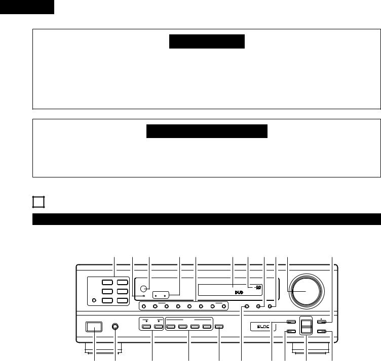
6 PART NAMES AND FUNCTIONS
Front Panel
• For details on the functions of these parts, refer to the pages given in parentheses ( ).
|
@1 @0 !9 |
|
!8!7 |
|
|
!6 !5 !4!38!2 |
|
!1 |
||||||
B PRECISION AUDIO COMPONENT / STEREO RECEIVER DRA-395 |
|
|
|
|
|
|
|
|
|
MASTER VOLUME |
|
|||
|
|
|
|
|
|
|
|
|
|
|
||||
|
CD |
PHONO |
|
|
|
|
|
|
|
|
|
|
|
|
|
|
|
|
|
|
|
|
|
|
|
VOLUME LEVEL |
|
|
|
|
|
REMOTE |
|
|
|
|
|
|
|
|
|
|
|
|
|
|
SENSOR |
|
|
|
|
|
|
|
|
|
|
|
|
|
TUNER |
DVD / VDP |
Multi Room |
|
|
|
|
|
|
|
|
|
|
|
|
|
|
Music Entertainment System |
|
|
|
|
|
|
|
|
|
|
|
|
|
ON / STANDBY |
ZONE 2 |
ZONE 3 |
|
|
|
|
|
|
|
|
|
|
CDR / TAPE |
VCR |
V.AUX |
|
|
|
|
|
|
|
|
|
|
|
|
|
|
SHIFT |
DOWN |
UP |
BAND |
MODE |
MEMORY |
DOWN |
UP |
VIDEO SELECT |
DIMMER |
STATUS |
|
|
|
|
|
PRESET |
|
|
|
|
TUNING |
|
|
|
|
|
|
|
|
|
|
|
|
|
|
|
|
|
|
TONE |
SELECT |
TREBLE |
ON / STANDBY |
|
PHONES |
SPEAKER |
|
REC / MULTI |
|
|
|
|
|
DEFEAT |
|||
|
|
A |
B |
REC OUT |
ZONE 2 |
ZONE 3 |
SELECT |
LOUDNESS |
|
|
|
UP |
|
|
|
|
|
|
|
|
|
|
|
|
|
|
|
DOWN |
|
|
|
|
|
|
|
|
|
|
|
|
|
CH VOL |
|
BASS |
q w e r t y u i o !0
q Power operation switch .................................................... |
(13, 21) |
w Headphone jacks (PHONES) ................................................... |
(19) |
e SPEAKER A/B buttons ................................................ |
(13, 19, 24) |
r REC/MULTI buttons .......................................................... |
(17, 18) |
t LOUDNESS button.................................................................. |
(15) |
y VIDEO SELECT button ............................................................ |
(19) |
u TONE DEFEAT button............................................................. |
(15) |
i CH VOL button........................................................................ |
(15) |
o SELECT UP/DOWN buttons.................................................... |
(15) |
!0BASS button............................................................................ |
(15) |
!1TREBLE button....................................................................... |
(15) |
!2MASTER VOLUME control ..................................................... |
(14) |
!3STATUS button ....................................................................... |
(20) |
!4DIMMER button...................................................................... |
(20) |
!5MASTER VOLUME indicator (VOLUME LEVEL) ..................... |
(14) |
!6Display |
|
!7Tuning/Preset memory selector buttons ........................ |
(21 23) |
!8ZONE 2, 3 indicator ................................................................. |
(18) |
!9Remote control sensor (REMOTE SENSOR) .......................... |
(11) |
@0Power indicator ....................................................................... |
(13) |
@1Input source selector buttons ........................................... |
(14, 22) |
10
ENGLISH
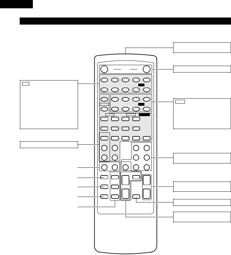
7 REMOTE CONTROL UNIT
Following the procedure outlined below, insert the batteries before using the remote control unit.
Range of operation of the remote control unit
Point the remote control unit at the remote control sensor as shown on the diagram at the left.
B

30°
30°
NOTES:
•The remote control unit can be used from a straight distance of approximately 7 meters/23 feet, but this distance will shorten or operation will become difficult if there are obstacles between the remote control unit and the remote control sensor, if the remote control sensor is exposed to direct sunlight or other strong light, or if operated from an angle.
•Neon signs or other devices emitting pulse-type noise nearby may result in malfunction, so keep the set as far away from such devices as possible.
Approx. 7 m/23 feet
Inserting the batteries
For remote control unit (RC-894)
qPress as shown by the arrow and slide off.
w Insert the R03/AAA batteries properly, |
e Close the lid. |
as shown on the diagram. |
|
NOTES:
•Be sure the polarities are correct. (See the illustration inside the battery compartment.)
•Remove the batteries if the remote control transmitter will not be used for an extended period of time.
•If batteries leak, dispose of them immediately. Avoid touching the leaked material or letting it come in contact with clothing, etc. Clean the battery compartment thoroughly before installing new batteries.
•Even if less than a year has passed, replace the batteries with new ones if the set does not operate even when the remote control unit is operated nearby the set. (The included battery is only for verifying operation. Replace it with a new battery as soon as possible.)
•When replacing the batteries, after removing them wait for about one minute before inserting the new batteries.
11
ENGLISH
Remote control unit (RC-894)
• For details on the functions of these parts, refer to the pages given in parentheses ( ).
CD
8, 9: Auto search (reverse and forward)
6, 7: Manual search (reverse and forward)
1: Play
2 |
: Stop |
3 |
: Pause |
RANDOM |
: RANDOM |
REPEAT |
: REPEAT |
DISC SKIP+ : Disc selection (CD changer only)
MULTI ROOM buttons ........................ |
(18) |
.........................SPEAKER buttons |
(13, 19) |
|
|
|
|
DIMMER button .................................. |
(20) |
|
|
|
|
STATUS button.................................... |
(20) |
|
|
|
|
VIDEO SELECT button ........................ |
(19) |
|
|
|
|
CH VOL control buttons ...................... |
(15) |
|
|
|
OFF |
POWER |
ON |
|
||
RANDOM |
6 |
7 |
8 |
|
|
9 |
REPEAT |
DISC SKIP |
3 |
2 |
|
CD |
1 |
|
A / B |
4REC |
3 |
|
|
2 |
ON |
|
|
|
|
|
|
MAIN |
6 |
7 |
0 TAPE |
1 |
||
OFF |
|
|
|
|
|
|
ZONE 2 |
ZONE 3 |
MULTI ROOM |
||||
ON |
• |
ON |
• |
|
|
|
|
VOLUME |
|
VOLUME |
|
||
OFF |
ª |
OFF |
ª |
|
|
|
TUNER |
PHONO |
V. AUX |
VCR |
|
DVD / VDP |
|
|
CD |
|
PHONO |
DVD / VDP |
||
• |
|
|
|
|
|
|
PRESET |
CDR / TAPE |
|
CD |
|
|
VCR |
ª |
|
|
|
|
|
|
A SPEAKER B |
TUNER |
CDR / TAPE |
V. AUX |
|||
DIMMER |
CH VOL |
|
SHIFT |
|
|
|
••
STATUS |
|
|
|
• |
PRESET |
|
MASTER VOL |
VIDEO SELECT |
ª |
MUTING |
ª |
ª |
|
|
|
B
REMOTE CONTROL UNIT RC-894
Remote control signal |
|
transmitter ........................................... |
(11) |
POWER buttons |
..................................(13) |
TAPE
0, 1 : Play (reverse and forward)
6, 7 : Rewind and Fast-forward
2: Stop
3: Pause
4REC |
: REC |
A / B |
: Tape A/B selection |
Input source selector |
|
buttons ................................................ |
(14) |
VOLUME control |
|
buttons ................................................ |
(14) |
MUTING button ................................... |
(19) |
Preset memory selector |
|
buttons ................................................ |
(23) |
12
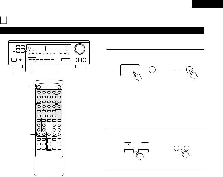
8 OPERATIONS
Before operating
B
1 |
1 |
2 |
|
|
|
1 |
|
|
|
1 |
OFF |
POWER |
ON |
|
|
|
|
RANDOM |
6 |
7 |
8 |
|
9 |
|
|
REPEAT |
DISC SKIP |
3 |
2 |
CD |
1 |
|
|
|
A / B |
4REC |
3 |
|
2 |
|
|
ON |
|
|
|
|
|
|
|
MAIN |
6 |
7 |
0 TAPE |
1 |
|
|
|
OFF |
|
|
|
|
|
|
|
ZONE 2 |
ZONE 3 MULTI ROOM |
||||
|
|
ON |
• |
ON |
• |
|
|
|
|
|
VOLUME |
|
VOLUME |
|
|
|
|
OFF |
ª |
OFF |
ª |
|
|
|
|
TUNER |
PHONO |
V. AUX |
VCR |
DVD / VDP |
|
|
|
|
CD |
|
PHONO |
DVD / VDP |
|
|
|
• |
|
|
|
|
|
|
|
PRESET |
CDR / TAPE |
|
CD |
|
VCR |
|
|
ª |
|
|
|
|
|
|
|
A SPEAKER B |
TUNER |
CDR / TAPE |
V. AUX |
||
|
|
2 |
|
|
|
|
|
|
|
DIMMER |
CH VOL |
|
SHIFT |
|
|
|
|
|
|
• |
|
|
• |
|
|
STATUS |
|
|
|
|
|
|
|
|
• |
PRESET |
|
MASTER VOL |
|
|
|
VIDEO SELECT |
|
ª |
MUTING |
|
ª |
|
|
|
ª |
|
|
|
|
B
REMOTE CONTROL UNIT RC-894
ENGLISH
Preparations:
Check that all connections are proper.
1 |
Turn on the power. |
|
|
|
Press the power operation switch (button). |
|
|||
|
ON / STANDBY |
|
|
|
|
|
OFF |
POWER |
ON |
|
(Main unit) |
(Remote control unit) |
||
•ON/STANDBY
When the button is pressed, the power turns on and the display lights.
When pressed again, the power turns off, the standby mode is set and the display turns off.
Several seconds are required from the time the power operation switch is set to the “ON” position until sound is output. This is due to the built-in muting circuit that prevents noise when the power operation switch is turned on and off.
2 |
Select the front speakers. |
|
Press the SPEAKER A or B button turn the speaker on. |
||
|
SPEAKER |
A SPEAKER B |
|
|
|
|
A |
B |
|
(Main unit) |
(Remote control unit) |
13
ENGLISH
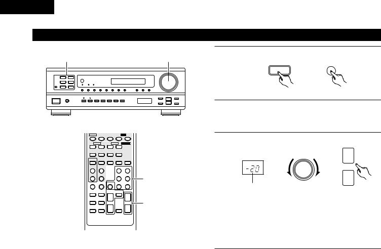
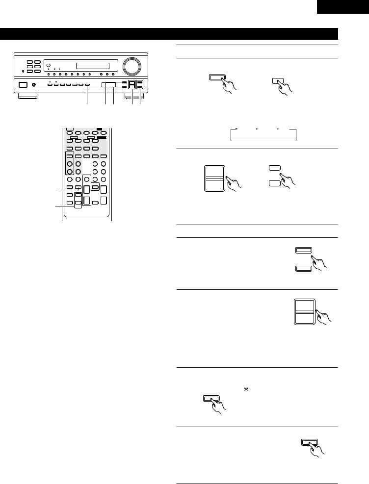
Playing the program source
1 |
3 |
1 |
Press the button for the program source to be played. |
||
EX: CD |
CD |
CD |
|||
B |
|
|
|
|
|
|
|
|
|
(Main unit) |
(Remote control unit) |
|
|
2 |
Start playback on the selected component. |
||
|
|
For operating instructions, refer to the various components’ |
|||
manuals.
MAIN |
6 |
7 |
0 TAPE 1 |
||
OFF |
|
|
|
|
|
ZONE 2 |
ZONE 3 |
MULTI ROOM |
|||
ON |
• |
ON |
• |
|
|
|
VOLUME |
|
VOLUME |
|
|
OFF |
ª |
OFF |
ª |
|
|
TUNER |
PHONO |
V. AUX |
VCR |
|
DVD / VDP |
|
CD |
|
PHONO |
DVD / VDP |
|
• |
|
|
|
|
|
PRESET |
CDR / TAPE |
|
CD |
|
VCR |
ª |
|
|
|
|
|
A SPEAKER B |
TUNER |
CDR / TAPE |
V. AUX |
||
DIMMER |
CH VOL |
|
SHIFT |
|
|
|
|
• |
|
|
• |
STATUS |
|
|
|
|
|
|
• |
PRESET |
|
|
MASTER VOL |
VIDEO SELECT |
|
ª |
MUTING |
ª |
|
|
ª |
|
|
|
|
B
REMOTE CONTROL UNIT RC-894
1
3
3 Adjust the volume.
MASTER VOLUME |
• |
MASTER VOL
ª
The volume level is
displayed on the master (Main unit) (Remote control unit) volume level display.

 The volume can be adjusted within the range of –60 to 0 to 18 dB, in steps of 1 dB. However, when the channel level is set as described on page 15, if the volume for any channel is set at +1 dB or greater, the volume cannot be adjusted up to 18 dB. (In this case the maximum volume adjustment range is “18 dB — (Maximum value of channel level)”.)
14
ENGLISH
Adjusting the CHANNEL LEVEL, TONE, and LOUDNESS control
Adjust the channel levels. |
|
B |
|
1 |
Select the channel whose level you want to adjust. |
CH VOL |
|
CH VOL
1
2
|
|
6 |
|
5 1 |
2, 4 |
3 |
MAIN |
6 |
7 |
0 TAPE 1 |
|
|
|
OFF |
|
|
|
|
|
|
ZONE 2 |
ZONE 3 MULTI ROOM |
|
|
|||
ON |
• |
ON |
• |
|
|
|
|
VOLUME |
|
VOLUME |
|
|
|
OFF |
ª |
OFF |
ª |
|
|
|
TUNER |
PHONO |
V. AUX |
VCR |
DVD / VDP |
|
|
|
CD |
|
PHONO |
DVD / VDP |
|
|
• |
|
|
|
|
|
|
PRESET |
CDR / TAPE |
|
CD |
VCR |
|
|
ª |
|
|
|
|
|
|
A SPEAKER B |
TUNER |
CDR / TAPE |
V. AUX |
|
|
|
DIMMER |
CH VOL |
|
SHIFT |
|
|
|
|
|
• |
|
• |
|
|
STATUS |
|
|
|
|
|
|
|
• |
PRESET |
|
MASTER VOL |
|
|
VIDEO SELECT |
|
ª |
MUTING |
ª |
|
|
|
ª |
|
|
|
|
|
B
REMOTE CONTROL UNIT RC-894
(Main unit) |
(Remote control unit) |
The channel switches as shown below each time the button is pressed.
L |
|
|
R |
|
|
SW |
|
|
|
|
2 |
Adjust the level of the selected channel. |
|
SELECT |
• |
|
|
UP |
|
|
DOWN |
ª |
|
|
|
|
(Main unit) |
(Remote control unit) |
The volume can be adjusted between -12 dB and +12 dB in units of 1 dB.
Adjusting the sound quality (tone)
3 |
Select the BASS or TREBLE whose you |
TREBLE |
want to adjust. |
|
BASS
(Main unit)
4 |
With the name of the volume to be |
SELECT |
adjusted selected, press the SELECT |
UP |
|
|
button to adjust the level. |
|
|
• To increase the bass or treble: Press |
DOWN |
|
the SELECT UP button. (The bass or |
|
|
treble sound can be increased to up to |
(Main unit) |
|
+12 dB in steps of 2 dB.) |
|
•To decrease the bass or treble: Press the SELECT DOWN button. (The bass or treble sound can be decreased to up to
–12 dB in steps of 2 dB.)
5 |
If you do not want the bass and treble to be adjusted, turn on |
|||
the tone defeat mode. |
|
|
||
|
TONE |
The signals do not pass through the |
||
|
DEFEAT |
bass and treble adjustment circuits, |
||
|
|
|||
|
|
providing higher quality sound. |
||
|
(Main unit) |
|
|
|
6 |
Press the LOUDNESS button. |
LOUDNESS |
||
Press the loudness button ON when |
||||
|
||||
listening to music at a low volume. The low notes and high notes will be
corrected to produce a natural sound.
(Main unit)

 LOUDNESS button can be used when the TONE DEFEAT ON mode.
15
Loading...