


DVD SURROUND SYSTEM
D-M71DVS
DVD SURROUND RECEIVER
ADV-M71
OPERATING INSTRUCTIONS
MODE D’EMPLOI
|
|
|
|
OFF |
|
|
ON |
|
|
|
|
|
|
|
VCR |
|
|
|
|
|
|
SLEEP |
|
REC |
TITLE |
TIME |
|
|
|
|
NTSC/PAL |
||||
|
|
|
|
SOURCE |
|
|
TV IN |
T V |
|
|
|
|
CLEAR |
|
ENTER |
CHARAC. |
EDIT/MENU |
|
|
|
|
A-B REPEAT |
SLIDE MODE |
ZOOM |
||
|
|
|
|
|
|
|
TV CH - |
TV CH + |
|
|
|
|
PROG/DIRECT |
|
REPEAT |
RANDOM |
CD SRS |
|
|
|
|
|
SEARCH MODE |
|||
|
|
|
|
MODE |
|
MEMO |
BAND |
|
|
|
|
|
|
|
|
|
TUNING / |
|
|
|
|
DVD |
|
TUNER |
D.AUX |
TV VOL |
|
|
|
|
1 |
|
2 |
3 |
+ |
|
|
|
|
MD/LINE-1 |
TAPE /LINE-2 |
|
- |
|
|
|
|
|
4 |
|
5 |
6 |
|
|
|
|
|
|
5CH STEREO |
AUTO DECODE |
TUNER |
|
|
|
|
|
7 |
|
8 |
9 |
+ |
|
|
|
|
DIRECT |
|
STEREO |
VIRTUAL |
CH |
|
|
|
|
CALL |
|
0/10 |
+10 |
- |
|
SURROUND / SELECT |
|
|
TEST TONE |
INPUT MODE |
SURROUND |
FUNCTION |
|
DVD SURROUND RECEIVER ADV-M71 |
|
|
|
|
|
|
|
|
PUSH - PARAM. |
|
|
|
|
|
|
|
|
|
|
|
|
|
|
|
TUNER TV / VCR |
|
|
|
|
|
A / V |
|
|
DVD |
IN/SURR. |
|
|
|
|
|
SYSTEM |
MD |
IN/SURR. |
|
|
|
|
|
|
|
|
CDR TAPE |
|
|
|
- |
+ |
1 |
|
|
2 |
+ |
|
MENU /SET |
|
BAND |
DVD |
|
|
|
|
|
VIRTUAL SPEAKER |
|
|
8 |
|
9 |
|
|
|
TONE / SDB |
VOLUME |
|
|
|
- |
||
|
|
|
|
6 |
|
7 |
||
|
FUNCTION |
|
|
|
|
STATUS |
|
|
|
|
|
|
3 |
|
|
MUTING |
|
ON / STANDBY |
|
|
|
SETUP |
|
|
|
TONE /SDB |
|
PHONES |
|
|
|
|
|
||
|
|
|
|
|
|
ENTER |
|
|
|
|
|
|
CH SELECT |
|
|
|
SURROUND |
|
|
|
|
|
|
|
PARAMETER |
|
|
|
|
|
|
|
|
- VCR CH + |
|
|
|
|
|
RETURN |
|
DISPLAY |
MENU |
TOP MENU |
|
|
|
|
ANGLE |
AUDIO SUB TITLE |
|||
RC-936
FOR ENGLISH READERS |
PAGE 4 ~ PAGE |
111 |
2We greatly appreciate your purchase of this unit.
2To be sure you take maximum advantage of all the features this unit has to offer, read these instructions carefully and use the set properly. Be sure to keep this manual for future reference should any questions or problems arise.
“SERIAL NO.
PLEASE RECORD UNIT SERIAL NUMBER ATTACHED TO THE REAR OF THE CABINET FOR FUTURE REFERENCE”
POUR LES LECTEURS FRANCAIS PAGE 112 ~ PAGE 219
2Nous vous remercions pour l’achat de cet appareil.
2Pour être sûr de profiter au maximum de toutes les caractéristiques qu’offre cet appareil, lire avec soin ces instructions et bien utiliser l’appareil. Toujours conserver ce mode d’emploi pour s’y référer ultérieurement en cas de question ou de problème.
“NO. DE SERIE
PRIERE DE NOTER LE NUMERO DE SERIE DE L’APPAREIL INSCRIT A L’ARRIERE DU COFFRET DE FAÇON A POUVOIR LE CONSULTER EN CAS DE PROBLEME.”
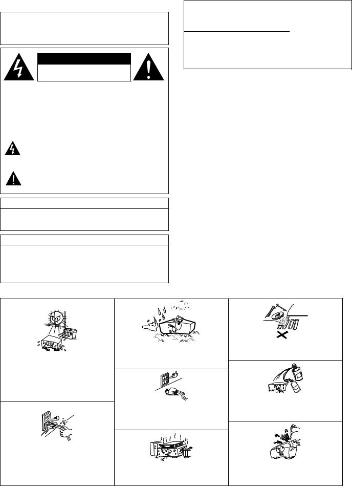
2SAFETY PRECAUTIONS
WARNING:
TO PREVENT FIRE OR SHOCK HAZARD, DO NOT EXPOSE THIS APPLIANCE TO RAIN OR MOISTURE.
CAUTION
RISK OF ELECTRIC SHOCK
DO NOT OPEN
CAUTION:
TO REDUCE THE RISK OF ELECTRIC SHOCK, DO NOT REMOVE COVER (OR BACK). NO USERSERVICEABLE PARTS INSIDE. REFER SERVICING TO QUALIFIED SERVICE PERSONNEL.
The lightning flash with arrowhead symbol, within an equilateral triangle, is intended to alert the user to the presence of uninsulated “dangerous voltage” within the product’s enclosure that may be of sufficient magnitude to constitute a risk of electric shock to persons.
The exclamation point within an equilateral triangle is intended to alert the user to the presence of important operating and maintenance (servicing) instructions in the literature accompanying the appliance.
CAUTION
TO PREVENT ELECTRIC SHOCK, MATCH WIDE BLADE OF PLUG TO WIDE SLOT, FULLY INSERT.
This device complies with Part 15 of the FCC Rules. Operation is subject to the following two conditions: (1) This device may not cause harmful interference, and (2) this device must accept any interference received, including interference that may cause undesired operation.
This Class B digital apparatus meets all requirements of the Canadian Interference-Causing Equipment Regulations.
Cet appareil numérique de la classe B respecte toutes les exigences du Règlement sur le matériel brouilleur du Canada.
CAUTION:
1.Handle the power supply cord carefully
Do not damage or deform the power supply cord. If it is damaged or deformed, it may cause electric shock or malfunction when used. When removing from wall outlet, be sure to remove by holding the plug attachment and not by pulling the cord.
2.Do not open the top cover
In order to prevent electric shock, do not open the top cover.
3.Do not place anything inside
Do not place metal objects or spill liquid inside the DVD video player. Electric shock or malfunction may result.
NOTE:
This DVD video player uses the semiconductor laser. To allow you to enjoy music at a stable operation, it is recommended to use this in a room of 5 °C (41 °F) ~ 35 °C (95 °F).
Copyrights
2It is prohibited by law to reproduce, broadcast, rent or play discs in public without the consent of the copyright holder.
ATTENTION
POUR ÉVITER LES CHOCS ÉLECTRIQUES,
INTERODUIRE LA LAME LA PLUS LARGE DE LA
FICHE DANS LA BORNE CORRESPONDANTE DE
LA PRISE ET POUSSER JUSQU’ AU FOND.
2NOTE ON USE / OBSERVATIONS RELATIVES A L’UTILISATION
•Avoid high temperatures.
Allow for sufficient heat dispersion when installed on a rack.
•Eviter des températures élevées
Tenir compte d’une dispersion de chaleur suffisante lors de l’installation sur une étagère.
•Handle the power cord carefully.
Hold the plug when unplugging the cord.
•Manipuler le cordon d’alimentation avec précaution.
Tenir la prise lors du débranchement du cordon.
•Keep the set free from moisture, water, and dust.
•Protéger l’appareil contre l’humidité, l’eau et lapoussière.
•Unplug the power cord when not using the set for long periods of time.
•Débrancher le cordon d’alimentation lorsque l’appareil n’est pas utilisé pendant de longues périodes.
*(For sets with ventilation holes)
•Do not obstruct the ventilation holes.
•Ne pas obstruer les trous d’aération.
•Do not let foreign objects in the set.
•Ne pas laisser des objets étrangers dans l’appareil.
•Do not let insecticides, benzene, and thinner come in contact with the set.
•Ne pas mettre en contact des insecticides, du benzène et un diluant avec l’appareil.
•Never disassemble or modify the set in any way.
•Ne jamais démonter ou modifier l’appareil d’une manière ou d’une autre.
2
SAFETY INSTRUCTIONS
1.Read Instructions – All the safety and operating instructions should be read before the product is operated.
2.Retain Instructions – The safety and operating instructions should be retained for future reference.
3.Heed Warnings – All warnings on the product and in the operating instructions should be adhered to.
4.Follow Instructions – All operating and use instructions should be followed.
5.Cleaning – Unplug this product from the wall outlet before cleaning. Do not use liquid cleaners or aerosol cleaners.
6.Attachments – Do not use attachments not recommended by the product manufacturer as they may cause hazards.
7.Water and Moisture – Do not use this product near water – for example, near a bath tub, wash bowl, kitchen sink, or laundry tub; in a wet basement; or near a swimming pool; and the like.
8.Accessories – Do not place this product on an unstable cart, stand, tripod, bracket, or table. The product may fall, causing serious injury to a child or adult, and serious damage to the product. Use only with a cart, stand, tripod, bracket, or table recommended by the manufacturer, or sold with the product. Any mounting of the product should follow the manufacturer’s instructions, and should use a
mounting accessory recommended by the
manufacturer.
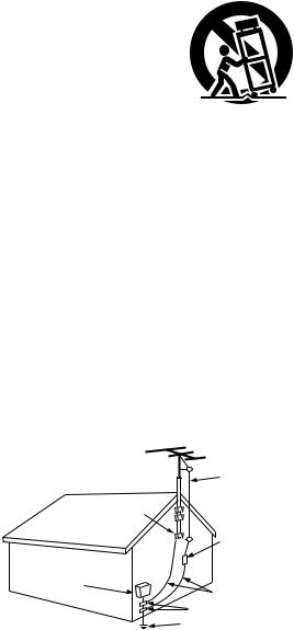
9. A product and cart combination should be moved with care. Quick stops, excessive force, and uneven surfaces may cause the product and cart combination to overturn.
10.Ventilation – Slots and openings in the cabinet are provided for ventilation and to ensure reliable operation of the product and to protect it from overheating, and these openings must not be blocked or covered. The openings should never be blocked by placing the product on a bed, sofa, rug, or other similar surface. This product should not be placed in a built-in installation such as a bookcase or rack unless proper ventilation is provided or the manufacturer’s instructions have been adhered to.
11.Power Sources – This product should be operated only from the type of power source indicated on the marking label. If you are not sure of the type of power supply to your home, consult your product dealer or local power company. For products intended to operate from battery power, or other sources, refer to the operating instructions.
12.Grounding or Polarization – This product may be equipped with a polarized alternating-current line plug (a plug having one blade wider than the other). This plug will fit into the power outlet only one way. This is a safety feature. If you are unable to insert the plug fully into the outlet, try reversing the plug. If the plug should still fail to fit, contact your electrician to replace your obsolete outlet. Do not defeat the safety purpose of the polarized plug.
FIGURE A
EXAMPLE OF ANTENNA GROUNDING
AS PER NATIONAL
ELECTRICAL CODE ANTENNA
LEAD IN
WIRE
GROUND
CLAMP
ANTENNA DISCHARGE UNIT
(NEC SECTION 810-20)
ELECTRIC
SERVICE
EQUIPMENT
GROUNDING CONDUCTORS (NEC SECTION 810-21)
GROUND CLAMPS
POWER SERVICE GROUNDING ELECTRODE SYSTEM
(NEC ART 250, PART H)
NEC - NATIONAL ELECTRICAL CODE
13.Power-Cord Protection – Power-supply cords should be routed so that they are not likely to be walked on or pinched by items placed upon or against them, paying particular attention to cords at plugs, convenience receptacles, and the point where they exit from the product.
15.Outdoor Antenna Grounding – If an outside antenna or cable system is connected to the product, be sure the antenna or cable system is grounded so as to provide some protection against voltage surges and built-up static charges. Article 810 of the National Electrical Code, ANSI/NFPA 70, provides information with regard to proper grounding of the mast and supporting structure, grounding of the lead-in wire to an antenna discharge unit, size of grounding conductors, location of antenna-discharge unit, connection to grounding electrodes, and requirements for the grounding electrode. See Figure A.
16.Lightning – For added protection for this product during a lightning storm, or when it is left unattended and unused for long periods of time, unplug it from the wall outlet and disconnect the antenna or cable system. This will prevent damage to the product due to lightning and power-line surges.
17.Power Lines – An outside antenna system should not be located in the vicinity of overhead power lines or other electric light or power circuits, or where it can fall into such power lines or circuits. When installing an outside antenna system, extreme care should be taken to keep from touching such power lines or circuits as contact with them might be fatal.
18.Overloading – Do not overload wall outlets, extension cords, or integral convenience receptacles as this can result in a risk of fire or electric shock.
19.Object and Liquid Entry – Never push objects of any kind into this product through openings as they may touch dangerous voltage points or short-out parts that could result in a fire or electric shock. Never spill liquid of any kind on the product.
20.Servicing – Do not attempt to service this product yourself as opening or removing covers may expose you to dangerous voltage or other hazards. Refer all servicing to qualified service personnel.
21.Damage Requiring Service – Unplug this product from the wall outlet and refer servicing to qualified service personnel under the following conditions:
a)When the power-supply cord or plug is damaged,
b)If liquid has been spilled, or objects have fallen into the product,
c)If the product has been exposed to rain or water,
d)If the product does not operate normally by following the operating instructions. Adjust only those controls that are covered by the operating instructions as an improper adjustment of other controls may result in damage and will often require extensive work by a qualified technician to restore the product to its normal operation,
e)If the product has been dropped or damaged in any way, and
f)When the product exhibits a distinct change in performance
– this indicates a need for service.
22.Replacement Parts – When replacement parts are required, be sure the service technician has used replacement parts specified by the manufacturer or have the same characteristics as the original part. Unauthorized substitutions may result in fire, electric shock, or other hazards.
23.Safety Check – Upon completion of any service or repairs to this product, ask the service technician to perform safety checks to determine that the product is in proper operating condition.
24.Wall or Ceiling Mounting – The product should be mounted to a wall or ceiling only as recommended by the manufacturer.
25.Heat – The product should be situated away from heat sources such as radiators, heat registers, stoves, or other products (including amplifiers) that produce heat.
3
ENGLISH
2INTRODUCTION
Thank you for choosing the DENON ADV-M71 DVD Surround Receiver. This remarkable component has been engineered to provide superb surround sound listening with home theater sources such as DVD, as well as providing outstanding high fidelity reproduction of your favorite music sources. As this product is provided with an immense array of features, we recommend that before you begin hookup and operation that you review the contents of this manual before proceeding.
TABLE OF CONTENTS
z BEFORE USING .......................................................................................... |
4 |
⁄3DOLBY / DTS SURROUND................................................................. |
46~48 |
x CAUTIONS ON INSTALLATION .............................................................. |
4, 5 |
⁄4SURROUND PLAYBACK..................................................................... |
49~61 |
c CAUTIONS ON HANDLING ........................................................................ |
5 |
⁄5LISTENING TO THE RADIO................................................................ |
62~64 |
v FEATURES .............................................................................................. |
5, 6 |
⁄6ON-SCREEN DISPLAY .............................................................................. |
65 |
b DISCS.......................................................................................................... |
6 |
⁄7USING THE ON-SCREEN DISPLAY .................................................... |
66~83 |
n CAUTIONS ON HANDLING DISCS............................................................. |
7 |
⁄8USING THE TIMER ............................................................................. |
84~90 |
m CONNECTIONS .................................................................................... |
8~15 |
⁄9CHANGING THE DEFAULT SETTINGS (DVD)................................... |
91~103 |
, PART NAMES AND FUNCTIONS ....................................................... |
16~20 |
¤0SYSTEM FUNCTION....................................................................... |
104~107 |
. REMOTE CONTROL UNIT.................................................................. |
21~28 |
¤1LAST FUNCTION MEMORY ................................................................... |
108 |
⁄0SETTING UP THE SYSTEM ................................................................ |
29~38 |
¤2INITIALIZATION OF THE MICROPROCESSOR ...................................... |
108 |
⁄1PLAY BACK......................................................................................... |
38~43 |
¤3TROUBLESHOOTING ..................................................................... |
109, 110 |
⁄2OPERATING THE SURROUND FUNCTIONS...................................... |
43~45 |
¤4SPECIFICATIONS .................................................................................... |
111 |
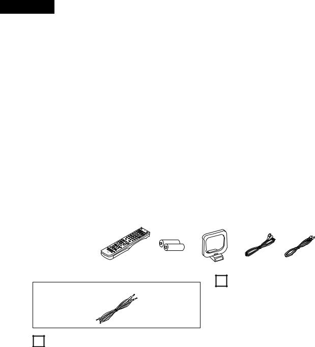
2ACCESSORIES
ADV-M71 |
|
Check that the following parts are included in addition to the main unit: |
|
|
|
|||||
q Operating instructions ..... |
1 |
w Warranty ( for North America model only ) |
...................... |
1 |
e Service station list................... |
1 |
r Remote control unit |
|
||
t R6P/AA batteries ............. |
2 |
y AM loop antenna............ |
|
1 u FM indoor antenna........ |
1 |
i Video cord ............................... |
1 |
(RC-936)........................ |
1 |
|
|
|
r |
|
t |
y |
|
u |
i |
|
|
|
|
|
|
|
|
|
|
|
|
|
|
|
|
|
|
|
|
|
|
|
|
SC-U71 [D-M71DVS only]
q Connecting cable (Approx. 3 m) .............................................................. |
2 |
1 BEFORE USING
Pay attention to the following before using this unit:
•Moving the set
To prevent short circuits or damaged wires in the connection cords, always unplug the power cord and disconnect the connection cords between all other audio components when moving the set.
•Before turning the power switch on
Check once again that all connections are proper and that there are not problems with the connection cords. Always set the power switch to the standby position before connecting and disconnecting connection cords.
•Store this instructions in a safe place.
After reading, store this instructions along with the warranty in a safe place.
•Note that the illustrations in this instructions may differ from the actual set for explanation purposes.
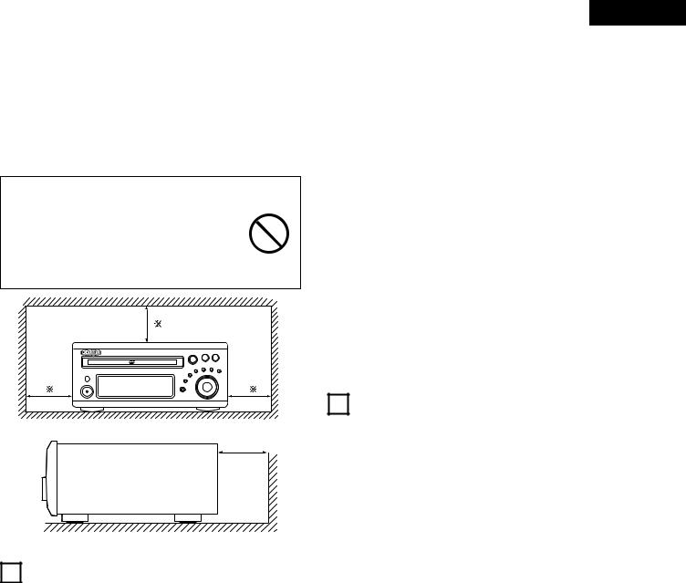
2CAUTIONS ON INSTALLATION
(1)DVD SURROUND RECEIVER UNIT
Noise or disturbance of the picture may be generated if this unit or any other electronic equipment using microprocessors is used near a tuner or TV.
If this happens, take the following steps:
•Install this unit as far as possible from the tuner or TV.
•Set the antenna wires from the tuner or TV away from this unit’s power cord and input/output connection cords.
•Noise or disturbance tends to occur particularly when using indoor antennas or 300 Ω/ohms feeder wires. We recommend using outdoor antennas and 75 Ω/ohms coaxial cables.
For heat dispersal, leave at least 10 cm/4 inch of space between the top, back and sides of this unit and the wall or other components.
(2) SPEAKER UNIT (D-M71DVS only)
The tone character produced by speaker systems depends on such factors as the size and type of room, the method of installation, etc. Pay attention to the following points when installing the speaker systems.
•If the bass sound is overemphasized when the speaker systems are installed directly on the floor, set them on concrete blocks or other hard stands.
•Note that howling may be produced if the speaker systems are placed on the same stand or shelf as a record player.
•If there are walls or glass doors behind or in front of the speaker systems, use heavy curtains, etc., to prevent resonance and reflection.
4
•This is an anti-magnet type speaker system which can be used near television sets, etc., but with some TV sets the colors may become blotchy. If this happens, turn off the TV’s power, wait 15 to 30 minutes, and turn the power back on. The TV’s self demagnetizing circuit will improve the picture. If the colors are still blotchy, move the speaker systems further away from the TV.
•Also note that if there is a magnet or any device generating magnetic force nearby, interaction between this device and the speaker systems can cause the colors on the TV to become blotchy.
WARNING
•For your safety, do not put anything nor lean yourself on the loudspeakers.
•Do not push the loudspeaker from aside to protect it from topping that may cause serious accident.
•Fix speaker cables to prevent being caught on it and making loudspeakers topping down.
10 cm/4 inch or more |
10 cm/4 inch or more
Wall |
3CAUTIONS ON HANDLING
(1)DVD SURROUND RECEIVER UNIT
•Switching the input function when input jacks are not connected
A clicking noise may be produced if the input function is switched when nothing is connected to the input jacks. If this happens, either turn down the MASTER VOLUME control or connect components to the input jacks.
•Muting of PRE OUT jacks, HEADPHONE jack and SPEAKER terminals
The PRE OUT jacks, HEADPHONE jacks and SPEAKER terminals include a muting circuit. Because of this, the output signals are greatly reduced for several seconds after the power switch is turned on or input function, surround mode or any other-set-up is changed. If the volume is turned up during this time, the output will be very high after the muting circuit stops functioning. Always wait until the muting circuit turns off before adjusting the volume.
•Whenever the power switch is in the STANDBY state, the apparatus is still connected on AC line voltage.
Please be sure to unplug the cord when you leave home for, say, a vacation.
ENGLISH
(2) SPEAKER UNIT [D-M71DVS only]
•Avoid placing the speaker systems in places exposed to direct sunlight for long periods of time or near heaters or other heating equipment.
•Placing in humid or dusty places may result in damage.
•Exposing the cabinet to insecticides or wiping it with benzene, thinner or other solvents may result in damage or discoloration to the finish. Use a soft cloth or silicone cloth to wipe any dirt off the cabinet. Use cloths containing chemical substances with care.
•Do not apply inputs exceeding the speaker system’s max. input (the input which can be applied a short period of time with regular program sources).
•The output terminals may differ depending on the amplifier being used. Consult the amplifier’s instructions.
•Clipping or other problems may occur in the output waveform when using the speaker systems with a high output and the amplifier’s tone controls set to the maximum. Avoid using them under these conditions.
•Never play such special signals as a tape recorder’s fast-forwarding signals or sine waves continuously.
•When moving the speaker systems, be careful not to apply excess force to the speaker nets. Doing so could damage the speaker units.
4 FEATURES
The ADV-M71 combines an AV amplifier and DVD player, the core components of a home theater system, into a single compact, stylish body. The system takes up little space, and the aluminum front panel and half mirror of the display make for an elegant design that blends in nicely with the décor in your room.
1.2-channel power amplifier with Dolby Virtual Speaker
compatibility
The ADV-M71 is equipped with two 35W (6 Ω/ohms 1kHz, T.H.D. 10%) power amplifiers that make it compatible with new Dolby Virtual Speaker technology for recreating a 5.1-channel environment virtually using a 2-channel configuration. (Dolby Virtual Speaker is an proprietary technology of Dolby Laboratories.) A high performance digital signal processor enables playback of Dolby Digital and DTS multi-channel surround signals in the Dolby Virtual Speaker mode. Surround sound can be achieved with the Dolby Virtual Speaker mode for CDs and other 2-channel sources in combination with the Dolby Pro Logic II decoder.
2.3.1-channel pre-out terminals allowing expansion into a 5.1- channel surround system
When used in combination with a commercially available subwoofer with built-in amplifier and power amplifier, the ADVM71 can be expanded into a 5.1-channel surround system. The ADV-M71 not only recreates an accurate sound field for multichannel sources, it is also compatible with wide mode playback in the Dolby Virtual Speaker mode.
3.Dolby Pro Logic II decoder for expanding sound field playback
The ADV-M71 is equipped with a Dolby Pro Logic II decoder for expanding sound field playback for Dolby Surround and stereo music sources.
4.DENON’s unique sound field simulation using the DSP
The ADV-M71 is compatible with the Rock Arena, Jazz Club and Video Game modes with a 2-channel configuration. In a 5.1- channel configuration, it is also compatible with the 5-Channel Stereo, Mono Movie and Matrix modes.
5
ENGLISH
5.High performance DVD drive for progressive image output compatibility
The ADV-M71 is compatible with various functions offered by DVD sources, including multiple audio (up to 8 languages), multiple subtitle (up to 32 languages), multiple angle playback, viewing restriction, etc.
6.Quick setup and on-screen display compatibility
DVDs can be enjoyed simply by selecting the TV and speaker configuration to be used. Even with a 5.1-channel speaker configuration, standard parameters can be set automatically simply by selecting the size of the room in which the system is being used and the listening position. The system can be set up using an on-screen display function.
7.Remote control unit with preset memory function
The ADV-M71 comes with a remote control unit equipped with a preset memory function including the remote control operation codes for D-M31 series cassette decks and DENON remote control compatible components as well as the remote control operation codes of other major brands of TVs and video decks.
8.Convenient system functions
When system connections are made with a D-M31 series cassette deck, such system functions as auto function selection, synchronized recording and timer recording/playback can be performed easily.
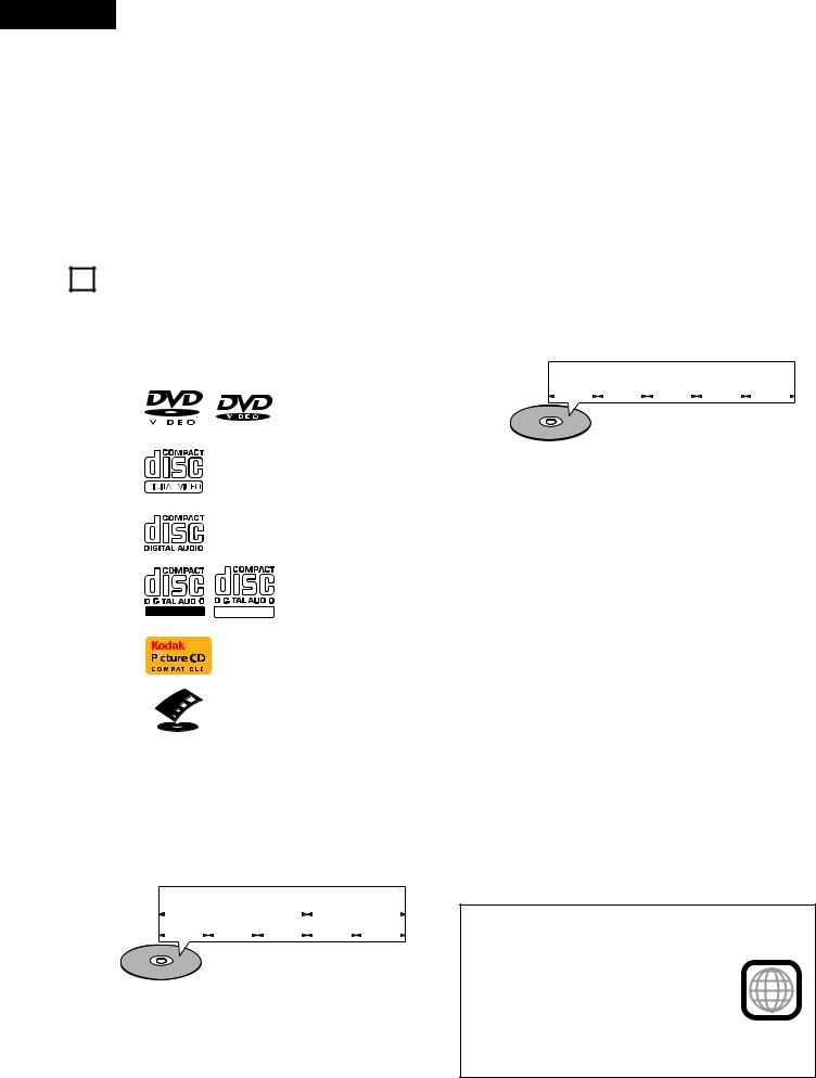
5DISCS
•The types of discs listed on the table below can be used on the ADV-M71. The marks are indicated on the disc labels or jackets.
Usable |
|
|
Mark (logo) |
Recorded |
Disc size |
|||||
discs |
|
|
signals |
|||||||
|
|
|
|
|
|
|
|
|
||
|
|
|
|
|
|
|
|
|
|
|
DVD video |
|
|
|
|
|
|
|
|
Digital audio + |
12 cm |
|
|
|
|
|
|
|
|
|
||
DVD audio |
|
|
|
|
|
|
|
|
digital video |
|
|
|
|
|
|
|
|
|
|
||
(NOTE 1) |
|
|
|
|
|
|
|
|
(MPEG2) |
8 cm |
|
|
|
|
|
|
|
|
|||
|
|
|
|
|
|
|
|
|
|
|
|
|
|
|
|
|
|
|
|
|
|
|
|
|
|
|
|
|
|
|
Digital audio + |
12 cm |
|
|
|
|
|
|
|
|
|
|
|
Video CD |
|
|
|
|
|
|
|
|
digital video |
|
|
|
|
|
|
|
|
|
|
||
|
|
|
|
|
|
|
|
|
(MPEG1) |
8 cm |
|
|
|
|
|
|
|
|
|
|
|
|
|
|
|
|
|
|
|
|
|
|
|
|
|
|
|
|
|
|
|
Digital audio |
12 cm |
CD |
|
|
|
|
|
|
|
|
|
|
|
|
|
|
|
|
|
|
MP3 |
|
|
CD-R |
|
|
|
|
|
|
|
|
|
|
|
|
|
|
|
|
|
|
WMA |
|
|
CD-RW |
|
|
|
|
|
|
|
|
|
|
|
|
|
|
|
|
|
|
Digital picture |
|
|
(NOTE 2) |
|
|
|
|
|
|
|
|
|
|
|
|
|
|
|
|
|
|
(JPEG) |
|
|
|
|
|
|
|
|
|
|
|
8 cm |
|
|
|
|
|
|
|
|
|
|
|
|
|
|
|
|
|
|
|
|
|
|
|
|
Recordable ReWritable |
|
|
|||||||
|
|
|
|
|
|
|
|
|
|
|
Picture CD |
|
|
|
|
|
|
|
|
Digital picture |
12 cm |
|
|
|
|
|
|
|
|
(JPEG) |
||
|
|
|
|
|
|
|
|
|
|
|
|
|
|
|
|
|
|
|
|
|
|
|
|
|
|
|
|
|
|
|
|
|
FUJICOLOR |
|
|
|
|
|
|
|
|
Digital picture |
12 cm |
CD |
|
|
|
|
|
|
|
|
(JPEG) |
|
|
|
|
|
|
|
|
|
|
||
|
|
|
|
|
|
|
|
|
|
|
2Disc terminology
•Titles and chapters (DVD-videos)
DVD-videos are divided into several large sections called “titles” and smaller sections called “chapters”.
Numbers are allotted to these sections. These numbers are called “title numbers” and “chapter numbers”.
For example:
|
|
|
Title 1 |
|
Title 2 |
|||||
|
|
|
|
|
|
|
|
|
|
|
Chapter 1 Chapter 2 Chapter 3 |
|
Chapter 1 Chapter 2 |
||||||||
|
|
|
|
|
|
|
|
|
|
|
|
|
|
|
|
|
|
|
|
|
|
•Tracks (video and music CDs)
Video and music CDs are divided into sections called “tracks”. Numbers are allotted to these sections. These numbers are called “track numbers”.
For example:
Track 1 |
|
|
|
Track 2 |
|
|
|
Track 3 |
|
|
Track 4 |
|
|
Track 5 |
2The following types of discs cannot be played on the ADVM71:
•DVDs with region numbers other than “1” or “ALL”
•DVD audio discs (NOTE 1)
•DVD+R/+RW
•DVD-ROM/RAMs
•CVD
•SVCD
•CD-ROMs (Only MP3/WMA file can be played)
•VSDs
•CDVs (Only the audio part can be played.)
•CD-Gs (Only the audio is output.)
•Photo CDs (NEVER play such discs on the ADV-M71)

 If you attempt to play photo CDs, the data on the disc may be damaged.
NOTE 1: Video part which based on DVD-video specification only can be played.
NOTE 2: According to recording quality, some CD-R/RW cannot be played.
•Playback control (video CDs)
Video CDs including the words “playback control” on the disc or jacket are equipped with a function for displaying menus on the TV screen for selecting the desired position, displaying information, etc., in dialog fashion.
In this manual, playing video CDs using such menus is referred to “menu playback”.
Video CDs with playback control can be used on the ADV-M71.
NOTE:
•This DVD video player is designed and manufactured to respond to the Region
Management Information that is recorded on a DVD disc.
If the Region number described on the DVD 1 disc does not correspond to the Region
number of this DVD video player, this DVD video player cannot play this disc.
The Region number for this DVD video player is 1.
6
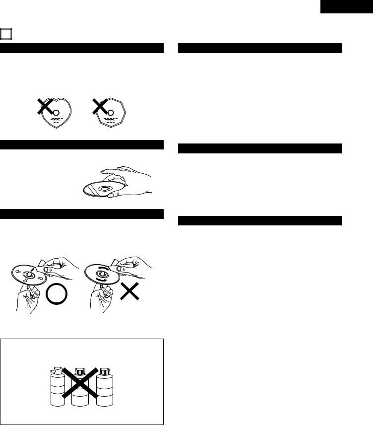
6 CAUTIONS ON HANDLING DISCS
Discs
Only the discs including the marks shown on page 6 can be played on the ADV-M71.
Note, however, that discs with special shapes (heart-shaped discs, hexagonal discs, etc.) cannot be played on the ADV-M71. Do not attempt to play such discs, as they may damage the player.
ENGLISH
Cautions on Handling Discs
•Do not get fingerprints, grease or dirt on discs.
•Be especially careful not to scratch discs when removing them from their cases.
•Do not bend discs.
•Do not heat discs.
•Do not enlarge the center hole.
•Do not write on the labeled (printed) side with a ball-point pen or a pencil.
•Water droplets may form on the surface if the disc is moved suddenly from a cold place to a warm one. Do not use a hairdryer, etc., to dry the disc.
Holding Discs
Avoid touching the surface of discs when loading and unloading them.
Be careful not to get fingerprints on the signal surface (the side which shines in rainbow colors).
Cautions on Storing Discs
•Always eject discs after playing them.
•Keep discs in their cases to protect them from dust, scratches and warping.
•Do not put discs in the following places:
1.Places exposed to direct sunlight for long periods of time
2.Humid or dusty places
3.Places exposed to heat from heaters, etc.
Cleaning Discs
2Fingerprints or dirt on the disc may lower sound and picture quality or cause breaks in playback. Wipe off fingerprints or dirt.
2Use a commercially available disc cleaning set or a soft cloth to wipe off fingerprints or dirt.
Wipe gently from the middle |
Do not wipe with a circular |
outwards. |
motion. |
NOTE:
•Do not use record spray or antistatic. Also do not use volatile chemicals such as benzene or thinner.
Record Thinner Benzene
spray
Cautions on Loading Discs
•Only load one disc at a time. Loading one disc on top of another may result in damage or scratch the discs.
•Load 8 cm discs securely in the disc guide, without using an adapter. If the disc is not properly loaded, it may slip out of the guide and block the disc tray.
•Be careful not to let your fingers get caught when the disc tray is closing.
•Do not place anything but discs in the disc tray.
•Do not load cracked or warped discs or discs that have been fixed with adhesive, etc.
•Do not use discs on which the adhesive part of cellophane tape or glue used to attach the label is exposed, or discs with traces of tape or labels that have been peeled off. Such discs may get stuck inside the player, resulting in damage.
7
ENGLISH
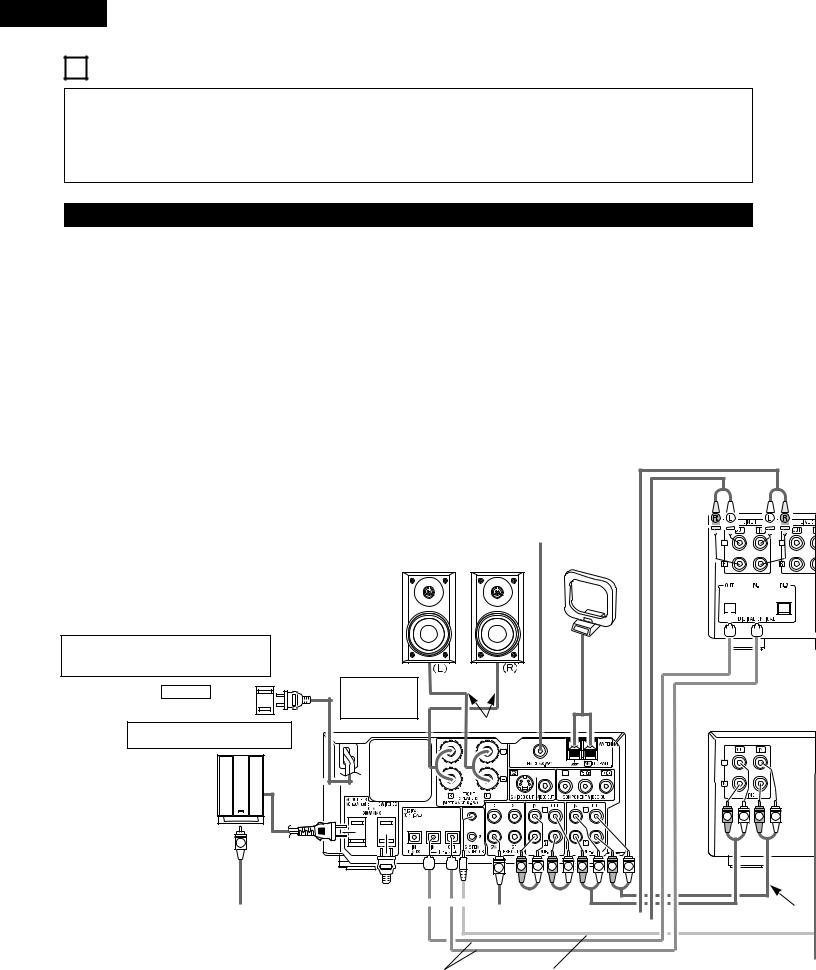
7 CONNECTIONS
•Do not plug in the AC cord until all connections have been completed.
•Be sure to connect the left and right channels properly (left with left, right with right).
•Insert the plugs securely. Incomplete connections will result in the generation of noise.
•Note that binding pin plug cords together with AC cords or placing them near a power transformer will result in generating hum or other noise.
•Noise or humming may be generated if a connected audio equipment is used independently without turning the power of this unit on. If this happens, turn on the power of the this unit.
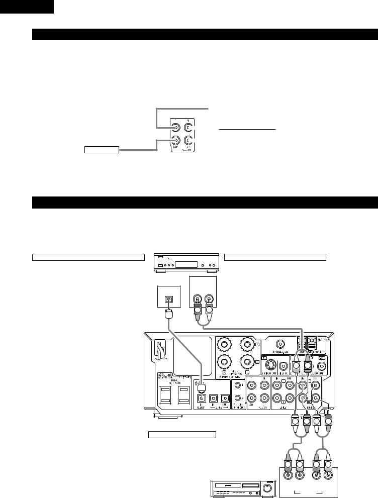
(1) Connecting the audio components (D-M31 series)
•The ADV-M71 can be used connected in a system with the D-M31 series cassette deck (DRR-M31).
•For instructions on operating the separately sold cassette deck (DRR-M31), refer to their respective operating instructions.
•Only the DRR-M31 cassette deck can be connected directly to the ADV-M71 using system connections.
NOTE: |
Connecting the speaker systems |
Connect the speaker system for the left channel (the left side as seen from the |
|
• This system includes digital circuitry which may cause interference such as |
front) to the L terminals, the speaker system for the right channel to the R |
color blotching or changes in the color on TVs. If this happens, move the |
terminals. Refer to the instructions supplied with the speaker system for details. |
system and the TV as far apart as possible. |
Be sure to use speaker systems with an impedance of 6 Ω/ohms or greater. |
|
|
Stereo audio cord
|
|
|
|
|
|
FM indoor antenna |
|
|
|
|
|
|
|
|
|
|
|
Speaker system |
|
|
|
|
|
|
|
|
|
|
|
|
|
|
|||
|
|
|
|
|
|
(included) |
|
|
|
|
|
|
|
|
|
|
|
SC-U71 [D-M71DVS only] |
|
|
|
|
|
|
|
|
|
|
|
|
|||||
Or commercially available |
AM loop antenna |
|
|
|
|
|
|
|
|
|
|
|
|||||
speaker |
|
|
|
|
|
|
|
|
|
|
|
||||||
(included) |
|
|
|
|
|
|
|
|
|
|
|
||||||
|
|
|
|
|
|
|
|
|
|
|
|
|
|
|
|
|
|
|
|
|
|
|
|
|
|
|
|
|
|
|
|
|
|
|
|
|
|
|
|
|
|
|
|
|
|
|
|
|
|
|
|
|
|
|
|
|
|
|
|
|
|
|
|
|
|
|
|
|
|
|
|
|
|
|
|
|
|
|
|
|
|
|
|
|
|
|
|
|
|
|
|
|
|
|
|
|
|
|
|
|
|
|
|
|
|
|
|
|
|
|
|
|
|
|
|
|
|
|
|
|
|
|
|
|
|
|
|
|
|
|
|
|
|
|
|
|
|
|
|
|
|
|
|
The ADV-M71 includes a built-in clock function, so plug its power cord into a wall power outlet to which electricity is supplied constantly.
AC CORD |
ADV-M71 DVD |
|
surround |
||
AC 120 V, 60 Hz |
||
receiver |
||
|
||
Commercially available subwoofer |
Speaker cords |
|
|
||
with built-in amplifier |
|
R |
L |
R |
L |
R |
L |
R |
L |
R |
L |
R |
L |
|
|
|
|
|
|
Stereo audio cord |
|
|
|
|
|
|
|
Audio cord |
|
|
|
|
|
|
|
|
|
|
|
||
|
|
|
|
|
|
|
Optical transmission |
System cords |
cables |
|
8
ENGLISH
CAUTION:
•Only one cassette deck can be connected to the ADV-M71 using system connections. System operations cannot be performed properly if two cassette decks are connected using system connections.
•Whenever the power operation switch is in the STANDBY position, the unit is still connected to AC line voltage.
•Please be sure to unplug the power cord when you leave home for, e.g.,a vacation, etc.
Note to CATV system installer:
This reminder is provided to call the CATV system installer’s attention to Article 820-40 of the NEC which provides guidelines for proper grounding and, in particular, specifies that the cable ground shall be connected to the grounding system of the building, as close to the point of cable entry as practical.
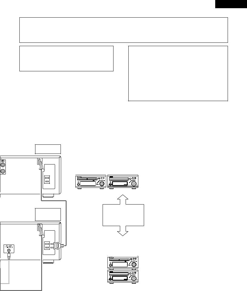
System operations
Such system operations as the timer and the auto power on functions, as well as remote control operations cannot be performed unless all the RCA pin-plug cords and system connector cords are connected between the units, so be sure to make all the connections properly as shown in the diagram. Also, disconnecting system connectors while the system is operating may result in malfunctions. Be sure to unplug the power cord before changing connections.
MD recorder (sold separately)
AC OUTLET AC 120V 60Hz UNSWITCHED 60W MAX
NOTES:
•Do not plug the power cord into the power outlet until all connections are completed. Be sure to interconnect the channels (L to L (white) and R to R (red)) properly, as shown on the diagram.
•Use the AC OUTLET for audio equipment only. Do not use them for hair driers, etc.
•Insert the plugs securely. Incomplete connections may result in noise.
•Be sure to connect the speaker cords between the speaker terminals and the speaker systems with the same polarities ( + to +, – to – ). If the polarities are switched, the sound at the center will be weak, the position of the different instruments will be unclear, and the stereo effect will be lost.
•After unplugging the power cord, wait about 5 seconds before plugging it back in.
•Note that setting the connection cords (pin-plug cords) next to the power cords may result in humming or other noise.
ADV-M71
Cassette deck (DRR-M31)
(sold separately)
AC OUTLET AC 120V 60Hz UNSWITCHED 60W MAX
DRR-M31
(Horizontal installation)
Install the sets as shown in one of these diagrams. In either case, be sure that the DVD surround receiver’s ventilation holes are not obstructed.
ADV-M71
DRR-M31
(Vertical installation)
9
ENGLISH
(2) Connecting the PRE OUT terminals (only with multi-channel settings)
•When used in combination with a commercially available subwoofer with built-in amplifier and power amplifier, the ADV-M71 can be expanded into a 5.1-channel surround system.
•When making connections, also refer to the operating instructions of the other components.
•To make the 5.1-channel setting, set the speakers to “5.1 CH SURROUND” in the quick system setup and select “Room Setting” and “Listening Position”. (See pages 31 to 32.)
IN
SUBWOOFER
•Connect the subwoofer with built-in amplifier.
|
IN |
|
|
|
|
|
POWER AMPLIFIER |
|
|
Center Speaker |
|
|
|
|
|
||
|
IN |
(for center ch) |
|
|
|
|
|
POWER AMPLIFIER |
|
|
Surround (L) Speaker |
|
|
|
|
||
|
|
(for Surround ch) |
|
|
|
|
IN |
|
|
|
|
|
|
|
|
|
|
|
• Connect the power |
|
|
Surround (R) Speaker |
|
|
|
amplifier for center and |
|
|
|
|
|
|
|
|
|
|
|
surround speaker |
|
|
|
|
|
system. |
|
|
|
(3) Connecting the Audio Signals of a Digital Satellite Tuner and VCR
•Connect the video signals directly to the TV and switch the picture on the TV.
•When making connections, also refer to the operating instructions of the other components.
Connection to the optical digital input terminal
•Only audio signals are input to the optical digital input terminal.
•Use a commercially available optical transmission cable for connection to the optical transmission terminal (OPTICAL).
Digital satellite/cable tuner
B
OPTICAL |
AUDIO |
OUT |
OUT |
R L |
Connection of a digital satellite/cable tuner
•For tuners equipped with an optical digital output terminal, connect the digital output terminal to the DIGITAL D.AUX IN terminal on the ADV-M71 using an optical transmission cable.
•To connect the audio output terminals, use whatever of the ADV-M71’s LINE-1 or LINE-2 terminals are open.
R L
L |
R |
L |
R |
L |
R |
Connection of a video deck
•Connect the video deck’s audio output and audio input terminals to whatever of the ADV-M71’s LINE-1 or LINE-2 terminals are open using pin-plug cords.
R |
L |
R |
L |
Video deck |
|
|
|
R |
L |
R |
L |
OUT |
|
IN |
|
|
|
AUDIO |
|
10
ENGLISH
(4) Connecting a TV
•When making connections, also refer to the operating instructions of the TV.
S VIDEO TV
S VEDEO OUT
• Connect the TV’s S video input (S-VIDEO INPUT) to the S-VIDEO OUT jack using a S jack connection cord.
VIDEO OUT
•Connect the TV’s video input (VIDEO INPUT) to the VIDEO jack using a video connection cord.
|
Monitor TV |
S-VIDEO |
VIDEO |
IN |
IN |
NOTES:
•Connect this unit video outputs to the TV either directly. Do not connect it via a VCR (video cassette recorder). Some discs contain copy prohibit signals. If such discs are played via a VCR, the copy prohibit system may cause disturbance in the picture.
•Set the “TV TYPE” in “VIDEO SETUP” in “DVD SETUP” to comply with your TV’s video format. When the TV is NTSC formated set to NTSC.
•When “PROGRESSIVE” is set, no video signals are output from the VIDEO OUT or S-VIDEO OUT terminals. Set “INTERLACED” if you want to use the VIDEO OUT or S-VIDEO OUT signals. (Refer to page 39)
11
ENGLISH
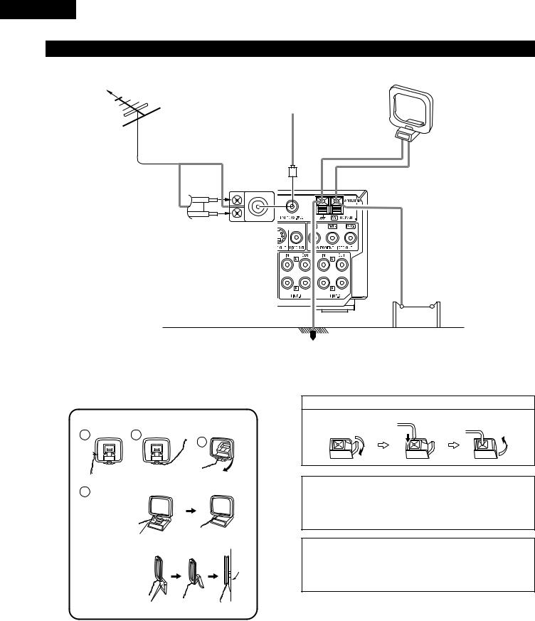
(5) Connecting the antenna terminals
DIRECTION OF |
AM LOOP ANTENNA |
BROADCASTING |
(Supplied) |
STATION |
|
|
FM INDOOR ANTENNA |
|
(Supplied) |
FM ANTENNA |
|
75 Ω/ohms |
|
COAXIAL |
|
CABLE |
|
FM ANTENNA ADAPTER (Option)
AM OUTDOOR
ANTENNA
GROUND
•An F-type FM antenna cable plug can be connected directly.
•If the FM antenna cable’s plug is not of the F-type, connect using the F-type antenna adapter (Option).
AM loop antenna assembly
1 |
2 |
Remove the vinyl tie and take out the
connection line.
4
a.With the antenna on top any stable
surface.
Mount
b.With the antenna attached to a wall.
Connect to the AM antenna terminals.
3
Bend in the reverse direction.
Connection of AM antennas
1. Push the lever. |
2. Insert the conductor. |
3. Return the lever. |
|||
|
|
|
|
|
|
|
|
|
|
|
|
|
|
|
|
|
|
|
|
|
|
|
|
|
|
|
|
|
|
Note to CATV system installer:
This reminder is provided to call the CATV system installer’s attention to Article 820-40 of the NEC which provides guidelines for proper grounding and, in particular, specifies that the cable ground shall be connected to the grounding system of the building, as close to the point of cable entry as practical.
NOTES:
•Do not connect two FM antennas simultaneously.
•Even if an external AM antenna is used, do not disconnect the AM loop antenna.
•Make sure AM loop antenna lead terminals do not touch metal parts of the panel.
Installation hole Mount on wall, etc.
12
ENGLISH
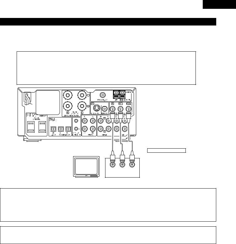
(6) Connecting to a TV or Monitor Equipped with Component Input Connectors.
•When making connections, also refer to the operating instructions of the other components.
•The video signals input to the VIDEO input (yellow) and S-Video input jacks are not output to the color difference (component) video jacks.
Color component output connectors (PR/CR, PB/CB and Y)
The red (PR/CR), blue (PB/CB) and brightness (Y) signals are output independently, achieving more faithful reproduction of the colors.
•The color component input connectors may be marked differently on some TVs or monitors (PR, PB and Y/R- Y, B-Y and Y/CR, CB and Y, etc.). For details, refer to the TV’s operating instructions.
Connect in this way if your TV is compatible with Progressive Scan.
Monitor TV
Y PB/CB PR/CR
COMPONENT VIDEO IN
Connecting a monitor TV
COMPONENT VIDEO OUT jack
•Connect the TV’s color difference (component) video input jacks (COMPONENT VIDEO INPUT) to the
COMPONENT VIDEO OUT jack using 75 Ω/ohms coaxial video pin-plug cords.
NOTES:
•Use the three commercially available video cords to connect the ADV-M71’s color component output connectors to the TV or monitor.
•Set the “TV TYPE” in “VIDEO SETUP” in “DVD SETUP” to comply with your TV’s video format. When the TV is NTSC formated set to NTSC.
•About selecting the video output “INTERLACED” or “PROGRESSIVE”, refer to page 39.
CONSUMERS SHOULD NOTE THAT NOT ALL HIGH DEFINITION TELEVISION SETS ARE FULLY COMPATIBLE WITH THIS PRODUCT AND MAY CAUSE ARTIFACTS TO BE DISPLAYED IN THE PICTURE. IN CASE OF 525 PROGRESSIVE SCAN PICTURE PROBLEMS, IT IS RECOMMENDED THAT THE USER SWITCH THE CONNECTION TO THE “STANDARD DEFINITION” OUTPUT.
13

ENGLISH
(7) Sound output from this unit digital and analog audio output connectors
2 When a disc is played on the ADV-M71 (DIGITAL OUT)
|
|
|
|
Settings |
Refer to |
Digital audio data output |
|
Audio recording format |
page |
||||
|
|
|
||||
|
|
|
|
|||
|
|
|
|
|
|
|
|
|
Dolby Digital |
Digital out : Normal |
|
Dolby Digital bitstream |
|
|
|
|
|
|
||
|
|
Digital out : PCM conversion |
98 |
2 channels PCM data (48 kHz/16bit) |
||
|
|
|
|
|||
|
|
|
|
|
|
|
|
|
|
DTS |
Digital out : Normal |
DTS bitstream |
|
|
|
|
|
|||
|
|
|
|
|
|
|
DVD video |
|
|
Digital out : PCM conversion |
|
2 channels PCM data (48 kHz/16bit) |
|
|
|
|
|
|||
|
|
|
|
|
|
|
DVD audio |
|
|
48 kHz |
LPCM conversion mode : OFF |
|
48 kHz/16 ~24 bit PCM |
(video part only) |
|
|
|
|
|
|
PCM |
|
LPCM conversion mode : ON |
|
48 kHz/16 bit PCM |
||
|
|
|
|
|||
|
|
|
|
|
|
|
|
|
96 kHz |
LPCM conversion mode : ON |
98 |
48 kHz/16 bit PCM |
|
|
Linear |
|
||||
|
|
|
|
|
|
|
|
|
CP : ON |
LPCM conversion mode : OFF |
|
48 kHz/16 bit PCM (when copy-protected) |
|
|
|
|
|
|
|
|
|
|
|
CP : OFF |
LPCM conversion mode : OFF |
|
96 kHz PCM (when not copy-protected) |
|
|
|
|
|
|
|
Video CD |
|
MPEG 1 |
|
|
44.1 kHz/16 bit PCM |
|
|
|
|
|
|
|
|
Music CD |
|
Linear PCM |
|
|
44.1 kHz/16 bit PCM |
|
|
|
|
|
|
|
|
MP3/WMA CD |
|
MP3/WMA |
|
|
32 ~ 48 kHz/16 bit PCM |
|
|
|
|
|
|
|
|
•Linear PCM audio is the signal recording format used for music CDs.
While the signals are recorded at 44.1 kHz/16 bit for music CDs, for DVDs they are recorded at 48 kHz/16 bit to 96 kHz/24 bit, providing higher sound quality than music CDs.
2 About the LINE-1 and LINE-2 analog recording outputs
When the DVD or the D.AUX digital input is selected:
•Dolby Digital, DTS, AAC and PCM digital signals are automatically converted to 2-channel stereo signals before being output (except when in the Dolby Headphone mode) and can be recorded in analog. (For what happens in the Dolby Headphone mode, see 3 below.)
When TUNER, LINE-1 or LINE-2 is selected:
•The selected analog audio signals from the tuner or from the device connected to the LINE-1 or LINE-2 analog input terminals (IN) are output unchanged, regardless of the ADV-M71’s input mode or surround mode. (The same is true for the device connected to the D.AUX terminals when “LINE-2” under “⁄0SETTING UP THE SYSTEM – (3) Detailed system setup – [5] Function settings” is set to “D.AUX”.)
Recording output during playback of a DVD, D.AUX or LINE-1 digital input source in the Dolby Headphone mode:
•In the Dolby Headphone mode with a DVD or a digital input selected, the Dolby Headphone mode analog audio signals currently being played are output and can be recorded in analog. (See pages 57 and 58.)
Cautions during analog recording of DVDs or digital input sources:
•Do not switch the ADV-M71’s input mode, surround mode or surround parameters during recording. Doing so will interrupt the sound being recorded.
We recommend setting the surround mode to “STEREO” or “DIRECT”.
•When using headphones, recording is automatically performed in the Dolby Headphone mode. Do not disconnect the headphones or switch the headphones mode during recording.
14
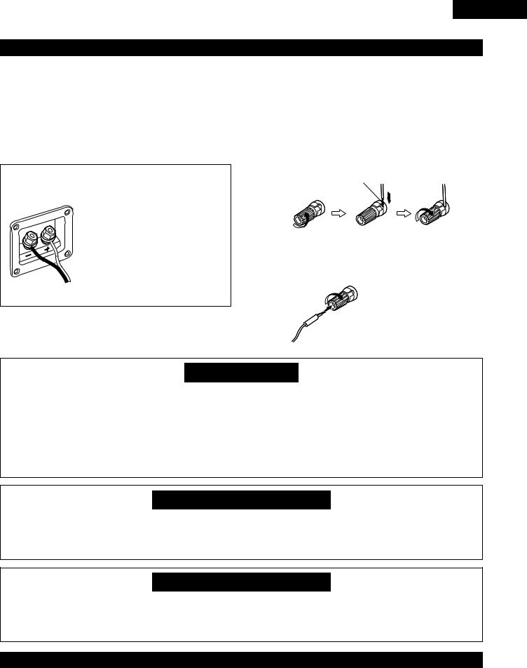
(8) Speaker system connections
Be sure to turn the amplifier’s power off when connecting the speaker systems.
•Use the included cables to connect the input terminals on the back of the speaker systems (see diagram) to the amplifier’s speaker output terminals. Connect the speaker system for the left channel amplifier’s “L” terminals, the one for the right channel to the amplifier’s “R” terminals, matching the polarities (“≈” and “√” marks). Inverting the polarities will result in unnatural sound, with the phase off or no low bass sound. Also check that all two terminal knobs are tightly fastened.
Connections
(The red terminals on the right side are the “≈” terminals, the black ones on the left side the “√” terminals.)
Connect to amplifier’s “√” side. (Silver color)
Loosen the terminals knobs, insert the cables’ core wires, then tighten the knobs.
Connect to amplifier’s “≈” side. (Copper color)
NOTE:
Make sure the core wires do not touch each other.
ENGLISH
Connecting the speaker cords
Use the included connection cords to connect the input terminals on the backs of the speaker systems (see the diagram at the right) to the ADV-M71’s speaker output terminals.
•Connect the speaker system for the left channel to the “L” terminals, the speaker system for the right channel to the “R” terminals, and be sure the polarities (“+” and “–”) are properly interconnected.
•Note that if the polarities are inverted, the phase may be off and the bass sound may be missing, resulting in an unnatural sound. Also check that both the speaker terminal’s screws are tightly screwed.
Either twist the core wires firmly or terminate the wires.
qTurn the speaker |
wInsert the cord’s |
eTurn clockwise to |
terminal |
core wires. |
tighten the |
counterclockwis |
|
terminal. |
e to loosen it. |
|
|
Connecting banana plugs
When using banana plugs, turn clockwise to tighten the terminal before inserting.
Protector circuit
•This unit is equipped with a high-speed protection circuit. The purpose of this circuit is to protect the speakers under circumstances such as when the output of the power amplifier is inadvertently short-circuited and a large current flows, when the temperature surrounding the unit becomes unusually high, or when the unit is used at high output over a long period which results in an extreme temperature rise.
When the protection circuit is activated, the speaker output is cut off and the power supply indicator LED flashes. Should this occur, please follow these steps: be sure to switch off the power of this unit, check whether there are any faults with the wiring of the speaker cables or input cables, and wait for the unit to cool down if it is very hot. Improve the ventilation condition around the unit and switch the power back on.
If the protection circuit is activated again even though there are no problems with the wiring or the ventilation around the unit, switch off the power and contact a DENON service center.
Note on speaker impedance
•The protector circuit may be activated if the set is played for long periods of time at high volumes when speakers with an impedance lower than the specified impedance (for example speakers with an impedance of lower than 4 Ω/ohms) are connected. If the protector circuit is activated, the speaker output is cut off. Turn off the set’s power, wait for the set to cool down, improve the ventilation around the set, then turn the power back on.
Cautions on connecting
•With this unit’s speaker outputs, signals with the reverse phase of the “+” side output terminal’s signals are also output from the “-” side output terminal.
Do not connect to a device for switching between multiple speakers (a speaker selector or audio channel selector) or connect in ways other than described in this manual. Doing so will result in damage.
(8) Removing the speaker net (D-M71DVS only)
•The net on the front of the speaker system is detachable.
•To remove it, grasp it on both sides and pull it towards you.
•To attach the net, line up the plastic pieces holes out of the net with the sticking in the cabinet and press in.
15
ENGLISH
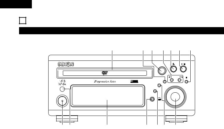
8 PART NAMES AND FUNCTIONS
Front Panel
• For details on the functions of these parts, refer to the pages given in parentheses ( ).
!4 |
!3!2 !1!0o i |
DVD SURROUND RECEIVER ADV-M71 |
SURROUND / SELECT |
PUSH - PARAM. |
|
- + |
MENU / SET |
BAND |
|
|
VIRTUAL SPEAKER |
|
TONE / SDB |
VOLUME |
|
|
FUNCTION |
|
ON / STANDBY
|
|
PHONES |
q w |
e |
r t y u |
q w e r t y u
Power button (ON/STANDBY).................................................. |
(30) |
Remote control sensor............................................................. |
(21) |
Display |
|
Headphones jack (PHONES) .................................................... |
(57) |
Function selector (FUNCTION)................................................. |
(43) |
Tone/super dynamic bass button (TONE/SDB) ........................ |
(45) |
Volume control (VOLUME) ....................................................... |
(41) |
i Stop/band button ( 2 BAND).............................................. |
(41, 62) |
o Play/pause button ( 1 / 3) ....................................................... |
(40) |
!0Open/close button ( 5 ) .......................................................... |
(40) |
!1Skip backward and forward buttons |
|
( 8 / – and + / 9 ) ..................................................... |
(42, 62) |
!2Surround/select knob (SURROUND/SELECT) .......................... |
(49) |
Surround parameter button (PARAMETER) ............................. |
(50) |
!3Menu/set button (MENU/SET) ................................................. |
(64) |
!4Disc holder ............................................................................... |
(39) |
16
ENGLISH
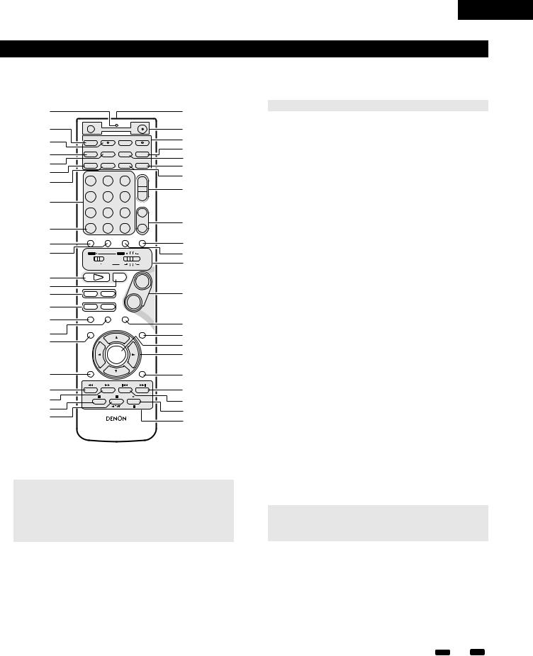
Remote control unit
•For details on the functions of these parts, refer to the pages given in parentheses ( ).
•Some of the buttons on the remote control unit have some functions.
The functions are switched using the remote control mode selector switches.
q |
|
|
|
|
@4 |
w |
OFF |
|
ON |
@5 |
|
|
|
VCR |
|
|
|
|
SLEEP |
REC |
TITLE |
TIME |
@6 |
e |
NTSC/PAL |
||||
SOURCE |
|
TV IN |
T V |
||
|
CLEAR |
ENTER |
CHARAC. |
EDIT/MENU |
@7 |
r |
A-B REPEAT |
SLIDE MODE |
ZOOM |
||
|
|
TV CH - |
TV CH + |
@8 |
|
|
PROG/DIRECT |
REPEAT |
RANDOM |
CD SRS |
|
t |
SEARCH MODE |
@9 |
|||
MODE |
MEMO |
BAND |
|
||
y |
|
|
|
TUNING / |
#0 |
DVD |
TUNER |
D.AUX |
TV VOL |
||
u |
1 |
2 |
3 |
+ |
#1 |
|
MD/LINE - 1 |
TAPE /LINE-2 |
|
- |
|
i |
4 |
5 |
6 |
|
|
|
5CH STEREO |
AUTO DECODE TUNER |
|
||
|
7 |
8 |
9 |
+ |
#2 |
|
DIRECT |
STEREO |
VIRTUAL |
CH |
|
o |
CALL |
0/10 |
+10 |
- |
|
!0 |
TEST TONE |
INPUT MODE SURROUND |
FUNCTION |
#3 |
|
|
|
|
|
||
!1 |
|
|
TUNER TV / VCR |
#4 |
|
|
A / V |
|
DVD |
IN/SURR. |
|
|
|
SYSTEM |
MD |
IN/SURR. |
#5 |
|
|
|
CDR |
TAPE |
|
!2 |
1 |
|
2 |
+ |
|
!3 |
DVD |
|
|
|
|
|
|
|
#6 |
||
!4 |
8 |
9 |
|
|
|
!5 |
6 |
7 |
- |
|
|
|
|
|
|
|
|
!6 |
|
STATUS |
|
|
|
3 |
|
MUTING |
#7 |
||
|
SETUP |
|
|
TONE /SDB |
|
!7 |
|
|
|
||
|
|
|
|
#8 |
|
!8 |
|
|
|
|
|
|
|
|
|
#9 |
|
|
|
|
|
|
|
|
|
ENTER |
|
$0 |
|
|
CH SELECT |
|
|
SURROUND |
|
|
|
|
PARAMETER |
|
|
!9 |
|
|
- VCR CH + |
$1 |
|
@0 |
|
|
$2 |
||
RETURN |
DISPLAY |
MENU |
TOP MENU |
||
@1 |
ANGLE AUDIO SUB TITLE |
$3 |
|||
@2 |
|
|
|
|
$4 |
@3 |
|
|
|
|
$5 |
|
|
RC-936 |
|
||
q Transmission indicator |
|
|
|
|
|
w Sleep timer button |
................................................................... |
|
|
|
(90) |
e NTSC/PAL button ..................................................................... |
|
|
|
|
(11) |
r Clear button.............................................................................. |
|
|
|
|
(70) |
t A-B repeat button..................................................................... |
|
|
|
|
(69) |
y Program/direct.......................................................................... |
|
|
|
|
(70) |
u Repeat button........................................................................... |
|
|
|
|
(68) |
iInput source/surround mode selector button
*System buttons ............................................(19, 20, 22, 23, 28)
o
!0Test tone button ....................................................................... |
(36) |
|
!1Input mode selector button...................................................... |
(43) |
|
!2DVD play button ....................................................................... |
(40) |
|
!3DVD stop button ...................................................................... |
(41) |
|
!4DVD skip buttons ..................................................................... |
(42) |
|
!5DVD search buttons ........................................................... |
(42, 43) |
|
!6DVD pause button.................................................................... |
(42) |
|
!7Status button............................................................................ |
(44) |
|
!8Setup button............................................................................. |
(30) |
|
!9Channel select button .............................................................. |
(36) |
|
|
|
|
@0 |
Return button ........................................................................... |
(41) |
@1 |
Display button .......................................................................... |
(66) |
@2 |
Angle button............................................................................. |
(80) |
@3 |
Audio selector button............................................................... |
(78) |
@4Remote control signal transmission window........................... |
(21) |
|
@5Power button............................................................................ |
(30) |
|
@6* System buttons............................................................... |
(19, 22) |
|
|
|
|
@7 |
Zoom button............................................................................. |
(83) |
@8 |
Slide mode button.................................................................... |
(77) |
@9 |
Search mode button................................................................. |
(42) |
#0 |
Random button......................................................................... |
(71) |
#1Tuner tuning +/– buttons .......................................................... |
(62) |
|
#2Tuner preset +/– buttons.......................................................... |
(64) |
|
#3Function selector button .......................................................... |
(43) |
|
#4Surround mode selector button ............................................... |
(44) |
|
#5Mode selector switches..................................................... |
(18, 19) |
|
#6Main volume control buttons ................................................... |
(41) |
|
#7Muting button........................................................................... |
(45) |
|
#8Tone/SDB button ...................................................................... |
(45) |
|
#9Enter button ............................................................................. |
(29) |
|
$0Cursor button ........................................................................... |
(29) |
|
$1Surround parameter button...................................................... |
(49) |
|
......................................................................$2Top menu button |
(81) |
|
$3Menu button............................................................................. |
(82) |
|
$4Subtitle button.......................................................................... |
(79) |
|
.........................................................$5* System buttons |
(19, 22, 28) |
|
• |
For details on the function and operation of the various parts, refer to the pages indicated in (parentheses). |
||
• |
Buttons indicated |
|
are DVD control buttons and can be operated when the remote control mode selector switch is set to the A / V and DVD |
|
position. |
|
|
• |
The functions of the system buttons (*) are switched using the remote control mode selector switch. |
||
17
ENGLISH
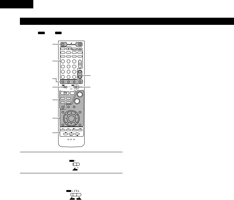
Names and functions of remote control unit buttons on the ADV-M71
• Buttons in sections q ~ e can be operated regardless of the position of mode switches 1 and 2.
• Consider A / V and DVD as standard positions, and switch as necessary to operate.
q |
OFF |
|
|
|
ON |
|
|
|
|
|
VCR |
|
|
|
|
|
|
SLEEP |
|
REC |
TITLE |
TIME |
|
|||
|
NTSC/PAL |
|
||||||
|
SOURCE |
|
|
TV IN |
T |
V |
|
|
|
CLEAR |
|
ENTER |
CHARAC. |
EDIT/MENU |
|
||
|
A-B REPEAT |
SLIDE MODE |
ZOOM |
|
||||
|
|
|
|
TV CH - |
TV CH + |
|
||
|
PROG/DIRECT |
|
REPEAT |
RANDOM |
CD SRS |
|
||
|
|
SEARCH MODE |
|
|||||
|
MODE |
|
MEMO |
BAND |
|
|
|
|
3 |
|
|
|
|
|
TUNING / |
|
|
DVD |
|
TUNER |
D.AUX |
TV VOL |
|
|||
1 |
|
2 |
3 |
+ |
|
|||
|
|
|
|
|
||||
|
MD/LINE-1 |
TAPE /LINE-2 |
|
|
- |
|
||
|
4 |
|
5 |
6 |
|
|||
|
|
5CH STEREO |
AUTO DECODE |
TUNER |
|
|||
|
7 |
|
8 |
9 |
+ |
e |
||
|
DIRECT |
|
STEREO |
VIRTUAL |
|
CH |
||
q |
CALL |
|
0/10 |
+10 |
- |
|||
TEST TONE |
INPUT MODE |
SURROUND |
FUNCTION |
|
||||
1 |
|
|
|
TUNER TV / VCR |
|
2 |
||
A / V |
|
|
DVD |
|
IN/SURR. |
|||
|
SYSTEM |
MD |
CDR TAPE IN/SURR. |
|||||
|
1 |
|
|
2 |
|
+ |
|
|
|
DVD |
|
|
|
|
|
||
w |
8 |
|
9 |
|
|
|
|
|
6 |
|
7 |
|
- |
|
|
||
|
|
|
STATUS |
|
|
|
|
|
|
3 |
|
|
|
MUTING |
|
|
|
|
SETUP |
|
|
|
|
TONE /SDB |
|
|
q |
|
|
ENTER |
|
|
|
|
|
|
CH SELECT |
|
|
|
|
SURROUND |
|
|
|
|
|
|
|
PARAMETER |
|
||
|
|
|
|
- VCR CH |
+ |
|
||
3 |
RETURN |
|
DISPLAY |
MENU |
TOP MENU |
|
||
ANGLE |
AUDIO |
SUB TITLE |
|
|
||||
|
|
|
RC-936 |
|
|
|
|
|
1 |
Set mode switch 1 to the “A/V” position. |
||
|
|||
|
A / V |
|
|
|
|
||
|
|
SYSTEM |
|
|
|
||
|
|
||
q Surround amplifier control buttons
ON |
: Turns the ADV-M71’s power on. |
OFF |
: Turns the ADV-M71’s power off. |
FUNCTION |
: Function selection (in order) |
SURROUND |
: Surround mode selection |
INPUT MODE : Input mode selection |
|
TEST TONE |
: Test tone on/off |
+: Main volume up
–: Main volume down
MUTING |
: Muting on/off |
STATUS |
: Status display selection |
TONE/SDB |
: Tone/SDB selection and setting |
SURROUND |
: Surround parameter selection and setting |
PARAMETER |
|
SET UP |
: Setup mode on/off |
CH SELECT |
: Channel level selection and setting |
•, ª, 0, 1 |
: Cursor up, down, left and right |
ENTER |
: Enter setting |
w DVD control buttons
1: Play (auto power on and auto function selection)
2 |
: Stop |
8, 9 |
: Skip (cueing) |
6, 7 |
: Search (fast-reverse and fast-forward) |
3: Pause and frame-by-frame
e Tuner control buttons
CH +/– : Preset channel up/down
(auto power on and auto function selection)
2 |
Set mode switch 2 to the position of the function you want to |
|||
|
||||
|
operate (DVD, TUNER or IN/SURR). |
|||
|
TUNER TV / VCR |
|||
|
DVD |
|
|
IN/SURR. |
|
|
|
||
|
|
|
|
|
|
|
|
|
|
|
|
|
|
|
18
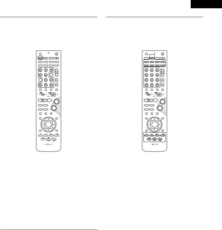
ENGLISH
3 |
Operate the ADV-M71. |
|
|
|
|
|
[1] Surround amplifier system buttons |
||||
|
(Operated with mode switch 2 set to “IN/SURR.”) |
||||
|
• These operations are possible with mode switch 1 at |
||||
|
any position. |
|
|
|
|
|
The operations in gray print can be performed. |
||||
|
|
OFF |
|
ON |
|
|
|
|
VCR |
|
|
|
|
SLEEP |
REC |
TITLE |
TIME |
|
|
NTSC/PAL |
|||
|
|
SOURCE |
|
TV IN |
T V |
|
|
CLEAR |
ENTER |
CHARAC. |
EDIT/MENU |
|
|
A-B REPEAT |
SLIDE MODE |
ZOOM |
|
|
|
|
|
TV CH - |
TV CH + |
|
|
PROG/DIRECT |
REPEAT |
RANDOM |
CD SRS |
|
|
SEARCH MODE |
|||
|
|
MODE |
MEMO |
BAND |
|
|
|
|
|
|
TUNING / |
|
|
DVD |
TUNER |
D.AUX |
TV VOL |
|
|
1 |
2 |
3 |
+ |
|
|
MD/LINE-1 |
TAPE /LINE-2 |
|
- |
|
|
4 |
5 |
6 |
|
|
|
|
5CH STEREO |
AUTO DECODE |
TUNER |
|
|
7 |
8 |
9 |
+ |
|
|
DIRECT |
STEREO |
VIRTUAL |
CH |
|
|
CALL |
0/10 |
+10 |
- |
|
|
TEST TONE |
INPUT MODE SURROUND |
FUNCTION |
|
|
|
|
|
TUNER TV / VCR |
|
|
|
A / V |
|
DVD |
IN/SURR. |
|
|
|
SYSTEM |
MD |
IN/SURR. |
|
|
|
|
CDR TAPE |
|
|
|
1 |
|
2 |
+ |
|
|
DVD |
|
|
|
|
|
8 |
9 |
|
|
|
|
6 |
7 |
- |
|
|
|
|
STATUS |
|
|
|
|
3 |
|
MUTING |
|
|
|
SETUP |
|
|
TONE /SDB |
|
|
|
ENTER |
|
|
|
|
CH SELECT |
|
|
SURROUND |
|
|
|
|
PARAMETER |
|
|
|
|
|
- VCR CH + |
|
|
|
RETURN |
DISPLAY |
MENU |
TOP MENU |
|
|
ANGLE AUDIO SUB TITLE |
|||
|
|
|
RC-936 |
|
|
|
SLEEP |
: Sleep on/off |
|
||
|
DVD |
: Function DVD |
|||
|
TUNER |
: Function TUNER |
|||
|
D.AUX |
: Function D.AUX |
|||
|
MD/LINE-1 |
: Function MD/LINE-1 |
|||
|
TAPE/LINE-2 |
: Function TAPE/LINE-2 |
|||
|
5CH STEREO : 5-channel stereo surround mode |
||||
|
|
(when “5.1CH” selected in setup) |
|||
|
AUTO DECODE : 2-channel mode switching when auto |
||||
|
|
decode surround mode set |
|||
|
|
(when “5.1CH” selected in setup) |
|||
|
VIRTUAL |
: 2-channel mode switching when Dolby |
|||
|
|
Virtual Speaker or Dolby VS surround mode |
|||
|
|
set |
|
|
|
|
STEREO |
: Stereo mode |
|
||
|
DIRECT |
: Direct mode |
|
||
[2]DVD system buttons
(Operated with mode switch 2 set to “DVD”)
OFF |
|
ON |
|
|
VCR |
|
|
SLEEP |
REC |
TITLE |
TIME |
NTSC/PAL |
|||
SOURCE |
|
TV IN |
T V |
CLEAR |
ENTER |
CHARAC. |
EDIT/MENU |
A-B REPEAT |
SLIDE MODE |
ZOOM |
|
|
|
TV CH - |
TV CH + |
PROG/DIRECT |
REPEAT |
RANDOM |
CD SRS |
SEARCH MODE |
|||
MODE |
MEMO |
BAND |
|
|
|
|
TUNING / |
DVD |
TUNER |
D.AUX |
TV VOL |
1 |
2 |
3 |
+ |
MD/LINE-1 |
TAPE /LINE-2 |
|
- |
4 |
5 |
6 |
|
|
5CH STEREO |
AUTO DECODE |
TUNER |
7 |
8 |
9 |
+ |
DIRECT |
STEREO |
VIRTUAL |
CH |
CALL |
0/10 |
+10 |
- |
TEST TONE |
INPUT MODE |
SURROUND |
FUNCTION |
|
|
TUNER TV / VCR |
|
A / V |
|
DVD |
IN/SURR. |
|
SYSTEM |
MD |
IN/SURR. |
|
|
CDR TAPE |
|
1 |
|
2 |
+ |
DVD |
|
|
|
8 |
9 |
|
|
|
|
- |
|
67
STATUS
3MUTING
SETUP TONE /SDB
ENTER
CH SELECT |
|
|
SURROUND |
|
|
PARAMETER |
|
|
|
- VCR CH + |
|
RETURN |
DISPLAY |
MENU |
TOP MENU |
ANGLE |
AUDIO |
|
SUB TITLE |
|
RC-936 |
|
|
NTSC/PAL |
: NTSC/PAL selection |
ZOOM |
: Zoom on/off |
SLIDE MODE : JPEG image slide mode selection
A-B REPEAT |
: A-B repeat playback setting |
CLEAR |
: Program clear |
SEARCH MODE: Title and chapter search selection
RANDOM |
: Random play on/off |
REPEAT |
: Repeat play setting |
PROG/DIRECT : Program/direct play selection
CALL |
: Program call |
0 ~ 9, +10 |
: Number buttons |
TOP MENU |
: Top menu call |
MENU |
: Menu call |
DISPLAY |
: Display call/selection |
RETURN |
: Menu return |
SUBTITLE |
: Subtitle language selection |
AUDIO |
: Audio language selection |
ANGLE |
: Angle selection |
|
|
19
ENGLISH
3 |
[3] Tuner system buttons |
|
|||
(Operated with mode switch 2 set to “TUNER”) |
|||||
|
|||||
|
OFF |
|
ON |
||
|
|
VCR |
|
|
|
|
SLEEP |
REC |
TITLE |
TIME |
|
|
NTSC/PAL |
||||
|
SOURCE |
|
TV IN |
T V |
|
|
CLEAR |
ENTER |
CHARAC. |
EDIT/MENU |
|
|
A-B REPEAT SLIDE MODE |
ZOOM |
|||
|
|
|
TV CH - |
TV CH + |
|
|
PROG/DIRECT |
REPEAT |
RANDOM |
CD SRS |
|
|
SEARCH MODE |
||||
|
MODE |
MEMO |
BAND |
|
|
|
|
|
|
TUNING / |
|
|
DVD |
TUNER |
D.AUX |
TV VOL |
|
1 2 3
MD/LINE-1 |
TAPE /LINE-2 |
4 5 6
+
-
|
5CH STEREO |
AUTO DECODE |
TUNER |
7 |
8 |
9 |
+ |
DIRECT |
STEREO |
VIRTUAL |
CH |
CALL |
0/10 |
+10 |
- |
TEST TONE |
INPUT MODE |
SURROUND |
FUNCTION |
|
|
TUNER TV / VCR |
|
A / V |
|
DVD |
IN/SURR. |
|
SYSTEM |
MD |
IN/SURR. |
|
|
CDR TAPE |
|
1 |
|
2 |
+ |
DVD |
|
|
|
8 |
9 |
|
|
|
|
- |
|
67
|
STATUS |
3 |
MUTING |
SETUP |
TONE /SDB |
ENTER
CH SELECT |
|
|
SURROUND |
|
|
PARAMETER |
|
|
|
- VCR CH + |
|
RETURN |
DISPLAY |
MENU |
TOP MENU |
ANGLE |
AUDIO |
|
SUB TITLE |
|
RC-936 |
|
|
BAND |
: FM/AM band selection |
MEMO |
: Preset memory |
MODE |
: FM auto/mono mode selection |
TUNER +/– |
: Tuning up/down |
1 ~ 10, +10 |
: Preset channel number buttons |
|
|
20
ENGLISH
9REMOTE CONTROL UNIT
•The included remote control unit (RC-936) can be used to operate not only this unit but other remote control compatible DENON components as well. In addition, the memory contains the control signals for other remote control units, so it can be used to operate non-DENON remote control compatible products.
(1) Inserting the batteries
q Remove the remote control unit’s rear cover.
wSet three R6P/AA batteries in the battery compartment in the indicated direction.
e Put the rear cover back on.
Notes on Batteries
•Use R6P/AA batteries in the remote control unit.
•The batteries should be replaced with new ones approximately once a year, though this depends on the frequency of usage.
•Even if less than a year has passed, replace the batteries with new ones if the set does not operate even when the remote control unit is operated nearby the set. (The included battery is only for verifying operation. Replace it with a new battery as soon as possible.)
•When inserting the batteries, be sure to do so in the proper direction, following the “≈” and “√” marks in the battery compartment.
•To prevent damage or leakage of battery fluid:
•Do not use a new battery together with an old one.
•Do not use two different types of batteries.
•Do not short-circuit, disassemble, heat or dispose of batteries in flames.
•Remove the batteries from the remote control unit when you do not plan to use it for an extended period of time.
•If the battery fluid should leak, carefully wipe the fluid off the inside of the battery compartment and insert new batteries.
•When replacing the batteries, have the new batteries ready and insert them as quickly as possible.
(2) Using the remote control unit
B
Approx. 7m / 22 feet
30°
|
|
|
+ |
|
|
|
- |
|
|
|
+ |
|
|
- |
30° |
- |
+ |
|
|
|
|
•Point the remote control unit at the remote sensor on the main unit as shown on the diagram.
•The remote control unit can be used from a straight distance of approximately 7 meters/22 feet from the main unit, but this distance will be shorter if there are obstacles in the way or if the remote control unit is not pointed directly at the remote sensor.
•The remote control unit can be operated at a horizontal angle of up to 30 degrees with respect to the remote sensor.
NOTES:
•It may be difficult to operate the remote control unit if the remote sensor is exposed to direct sunlight or strong artificial light.
•Do not press buttons on the main unit and remote control unit simultaneously. Doing so may result in malfunction.
•Neon signs or other devices emitting pulse-type noise nearby may result in malfunction, so keep the set as far away from such devices as possible.
21
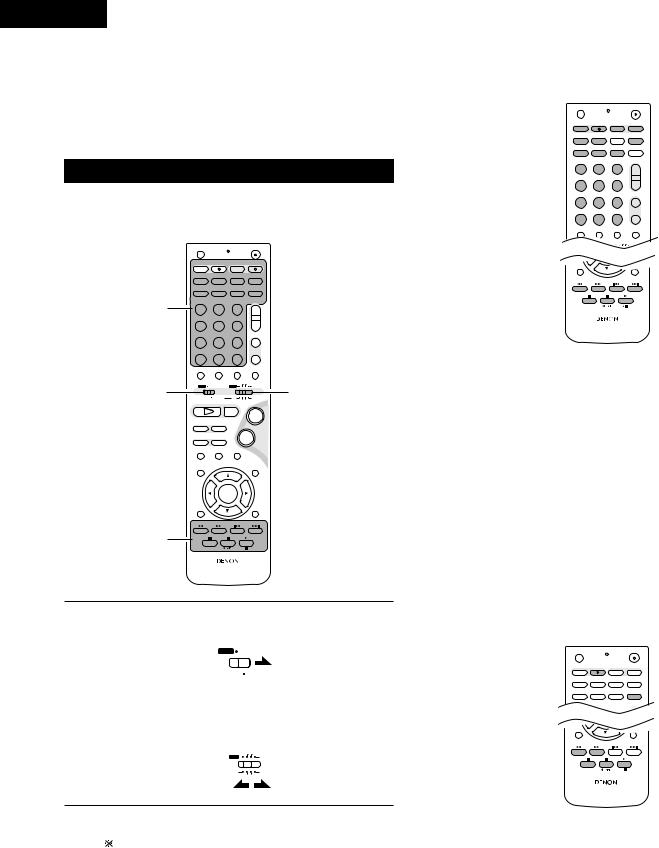
ENGLISH
• The included remote control unit (RC-936) can be used to operate |
|
|
|
|
|
|
|
3 |
[1] CD recorder system buttons |
|
|||||
not only the ADV-M71 but also to perform system operations for |
|
||||||
(operated with mode switch 2 set to “CDR”) |
|||||||
the D-M31 series and to operate other remote control compatible |
|||||||
DENON products. In addition, the remote control operation codes |
|
|
|
|
|
|
|
of other major brands of TVs and video decks are also stored in the |
|
|
OFF |
|
ON |
||
remote control unit, so the unit can be used to operate these TVs |
|
|
|
VCR |
|
|
|
|
|
SLEEP |
REC |
TITLE |
TIME |
||
|
|
|
NTSC/PAL |
||||
and video decks as well. |
|
|
SOURCE |
|
TV IN |
T V |
|
|
|
CLEAR |
A-B REPEAT SLIDE MODE |
ZOOM |
|||
|
|
|
|
ENTER |
CHARAC. |
EDIT/MENU |
|
|
|
|
|
|
TV CH - |
TV CH + |
|
|
|
|
PROG/DIRECT |
REPEAT |
RANDOM |
CD SRS |
|
|
|
|
SEARCH MODE |
||||
|
|
|
MODE |
MEMO |
BAND |
|
|
|
|
|
|
|
|
TUNING / |
|
|
|
|
DVD |
TUNER |
D.AUX |
TV VOL |
|
(3)Operating DENON audio components
•Turn on the power of all the components before operating them.
•Depending on the model and year of make of your component, some of the keys may not work.
|
OFF |
|
ON |
|
|
|
VCR |
|
|
|
SLEEP |
REC |
TITLE |
TIME |
|
NTSC/PAL |
|||
|
SOURCE |
|
TV IN |
T V |
|
CLEAR |
ENTER |
CHARAC. |
EDIT/MENU |
|
A-B REPEAT |
SLIDE MODE |
ZOOM |
|
|
|
|
TV CH - |
TV CH + |
|
PROG/DIRECT |
REPEAT |
RANDOM |
CD SRS |
|
SEARCH MODE |
|||
|
MODE |
MEMO |
BAND |
|
3 |
|
|
|
TUNING / |
DVD |
TUNER |
D.AUX |
TV VOL |
|
1 |
2 |
3 |
+ |
|
1 |
|
2 |
|
3 |
+ |
MD/LINE-1 |
TAPE /LINE-2 |
|
|
- |
|
4 |
|
5 |
|
6 |
|
|
5CH STEREO |
AUTO DECODE |
TUNER |
||
7 |
|
8 |
|
9 |
+ |
DIRECT |
|
STEREO |
|
VIRTUAL |
CH |
CALL |
|
0/10 |
|
+10 |
- |
TEST TONE |
INPUT MODE |
SURROUND |
FUNCTION |
||
|
|
|
|
TUNER TV / VCR |
|
A / V |
|
|
DVD |
IN/SURR |
|
CH SELECT |
|
|
|
|
SURROUND |
|
|
|
|
PARAMETER |
|
|
|
|
|
- VCR CH + |
|
RETURN |
|
DISPLAY |
|
MENU |
TOP MENU |
ANGLE |
AUDIO |
SUB TITLE |
|||
MD/LINE-1 |
TAPE /LINE-2 |
|
- |
|
4 |
5 |
6 |
RC-936 |
|
|
||||
|
5CH STEREO |
AUTO DECODE |
TUNER |
|
7 |
8 |
9 |
+ |
|
DIRECT |
STEREO |
VIRTUAL |
|
CH |
1
3
CALL |
0/10 |
+10 |
- |
|
TEST TONE |
INPUT MODE |
SURROUND |
FUNCTION |
|
|
|
TUNER TV / VCR |
2 |
|
A / V |
|
DVD |
IN/SURR. |
|
|
SYSTEM |
MD CDR |
TAPE IN/SURR. |
|
1 |
|
2 |
+ |
|
DVD |
|
|
|
|
8 |
9 |
|
|
|
|
|
- |
|
|
67
STATUS
3MUTING
SETUP TONE /SDB
ENTER
CH SELECT |
|
|
SURROUND |
|
|
PARAMETER |
|
|
|
- VCR CH + |
|
RETURN |
DISPLAY |
MENU |
TOP MENU |
ANGLE |
AUDIO |
|
SUB TITLE |
RC-936
TIME |
: Disc time display |
TITLE |
: Name display and selection of characters when |
|
inputting names |
REC |
: Recording |
SOURCE |
: CD recorder power on/off |
EDIT/MENU |
: Menu selection |
ENTER |
: Entering of menu items |
CLEAR |
: Program clearing |
RANDOM |
: Random play on/off |
REPEAT |
: Repeat play setting |
PROG/DIRECT : Program/direct playback selection |
|
CALL |
: Program calling |
1~10, +10 |
: Track number selection |
8, 9 |
: Auto search (cueing) |
6, 7 |
: Manual search (fast-reverse and fast-forward) |
1 (/ 3) |
: Play (play/pause, auto power on and auto function |
|
selection with the CDR-M30) |
3: Pause
2: Stop
1 |
Set mode switch 1 to the “SYSTEM” position. |
||||||
|
|
||||||
|
|
(Blue print) |
|
|
|
|
|
|
|
A / V |
|
|
|
|
|
|
|
|
|
|
SYSTEM |
||
|
|
|
|
|
|
||
|
|
|
|
|
|
||
|
|
|
|
|
|
||
|
|
|
|
|
|
|
|
2 |
Set mode switch 2 to the position for the component to be |
||||||
|
|
||||||
|
|
operated (MD, CDR or TAPE). |
|||||
|
|
(Blue print) |
|
|
|
|
|
|
|
TUNER TV / VCR |
|||||
|
|
DVD |
|
|
IN/SURR. |
||
|
|
MD |
|
|
IN/SURR. |
||
|
|
|
|
||||
|
|
|
|
||||
|
|
|
|
CDR TAPE |
|||
[2]Tape deck system button
(operated with mode switch 2 set to “TAPE”)
OFF |
|
|
ON |
|
|
VCR |
|
|
|
SLEEP |
REC |
|
TITLE |
TIME |
NTSC/PAL |
|
|||
SOURCE |
|
|
TV IN |
T V |
CLEAR |
ENTER |
|
CHARAC. |
EDIT/MENU |
A-B REPEAT |
SLIDE MODE |
ZOOM |
||
|
|
|
TV CH - |
TV CH + |
PROG/DIRECT |
REPEAT |
|
RANDOM |
CD SRS |
|
SEARCH MODE |
|||
MODE |
MEMO |
|
BAND |
|
|
|
|
|
TUNING / |
DVD |
TUNER |
|
D.AUX |
TV VOL |
CH SELECT |
|
|
|
SURROUND |
|
|
|
PARAMETER |
|
|
|
|
- VCR CH + |
|
RETURN |
DISPLAY |
|
MENU |
TOP MENU |
ANGLE |
AUDIO |
SUB TITLE |
||
RC-936
3 |
Operate the audio component. |
|
|
|
• For details, refer to the component’s operating instructions. |
|
Operation may not be possible for some models. |
|
|
REC |
: Recording |
CD SRS |
: CD synchronized recording (DRR-M31 system |
|
function) |
6, 7 |
: Rewind and fast-forward |
1: Forward direction play
0 TAPE |
: Reverse direction play (0 and 1: auto power on |
|
and auto function selection with the DRR-M31) |
|
|
22
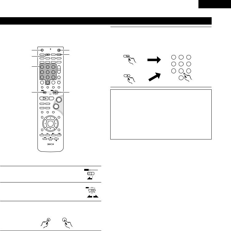
(4)TV and video deck preset memories
•Components of other brands can be operated with the included remote control unit by storing their codes in the preset memory. Note that depending on the model some operations may not be possible and some buttons may not operate properly.
3 |
OFF |
|
ON |
3 |
|
|
VCR |
|
|
||
SLEEP |
REC |
TITLE |
TIME |
||
NTSC/PAL |
4 |
||||
4 |
SOURCE |
|
TV IN |
T V |
|
CLEAR |
ENTER |
CHARAC. |
EDIT/MENU |
||
A-B REPEAT |
SLIDE MODE |
ZOOM |
|||
|
|
TV CH - |
TV CH + |
|
|
|
PROG/DIRECT |
REPEAT |
RANDOM |
CD SRS |
|
|
SEARCH MODE |
|
|||
|
MODE |
MEMO |
BAND |
|
|
4 |
|
|
|
TUNING / |
|
DVD |
TUNER |
D.AUX |
TV VOL |
|
|
1 |
2 |
3 |
+ |
|
|
|
MD/LINE-1 |
TAPE /LINE-2 |
|
- |
|
|
4 |
5 |
6 |
|
|
|
|
5CH STEREO |
AUTO DECODE |
TUNER |
|
|
7 |
8 |
9 |
+ |
|
|
DIRECT |
STEREO |
VIRTUAL |
CH |
|
|
CALL |
0/10 |
+10 |
- |
|
|
TEST TONE |
INPUT MODE |
SURROUND |
FUNCTION |
|
1 |
|
|
TUNER TV / VCR |
2 |
|
A / V |
|
DVD |
IN/SURR. |
||
|
SYSTEM |
MD CDR TAPE IN/SURR. |
|||
|
1 |
|
2 |
+ |
|
|
DVD |
|
|
|
|
|
8 |
9 |
|
|
|
|
6 |
7 |
- |
|
|
|
|
STATUS |
|
|
|
|
3 |
|
MUTING |
|
|
|
SETUP |
|
|
TONE /SDB |
|
ENTER
CH SELECT |
|
|
SURROUND |
|
|
PARAMETER |
|
|
|
- VCR CH + |
|
RETURN |
DISPLAY |
MENU |
TOP MENU |
ANGLE |
AUDIO |
|
SUB TITLE |
RC-936
2 Not set upon shipment from the factory.
1 |
Set mode switch 1 to the “A/V” position. |
A / V |
SYSTEM |
||
2 |
Set mode switch 2 to the “TV/VCR” position. |
TUNER TV / VCR |
|||
|
|
DVD |
IN/SURR. |
||
|
|
MD |
IN/SURR. |
||
3 |
|
|
|
CDR TAPE |
|
Press the power ON button and the OFF button |
|||||
|
|||||
|
simultaneously. |
|
|
|
|
|
• The transmission LED (indicator) flashes. |
|
|
||
|
OFF |
ON |
|
|
|
ENGLISH
4 |
Press the TV button to preset a TV, the VCR button to preset |
|||
|
||||
|
a video deck, then input the 3-digit number corresponding to |
|||
|
the brand of the component whose signals are to be stored in |
|||
|
the preset memory (refer to the tables of remote control |
|||
|
codes on pages 24 to 27). |
|
|
|
|
TIME |
DVD |
TUNER |
D.AUX |
|
T |
1 |
2 |
3 |
|
|
|||
|
|
MD/LINE-1 |
TAPE /LINE-2 |
|
|
|
4 |
5 |
6 |
|
|
|
5CH STEREO |
AUTO DECODE |
|
VCR |
7 |
8 |
9 |
|
REC |
|
|
|
|
NTSC/PAL |
|
STEREO |
|
|
|
|
|
|
|
|
|
0/10 |
|
NOTES: |
|
|
|
|
• |
When buttons are |
while setting the preset memory, |
||
|
their signals are |
remote control transmitter, so |
||
|
cover the remote |
sensor when setting the preset |
||
|
memory to prevent |
operation. |
|
|
• |
Depending on the |
year of make, some of the remote |
||
|
control codes for |
included on the tables may not |
||
|
operate properly. |
|
|
|
• |
For some brands |
multiple types of remote control |
||
|
codes. If an operation |
work, try changing to one of the |
||
|
other codes. |
|
|
|
23

ENGLISH
Combinations of preset codes for different brands
TV
Admiral |
045, 121 |
|
|
Adventura |
122 |
|
|
Aiko |
054 |
|
|
Akai |
016, 027, 046 |
|
|
Alleron |
062 |
|
|
A-Mark |
007 |
|
|
Amtron |
061 |
|
|
Anam |
006, 007, 036 |
|
|
Anam National |
061, 147 |
|
|
AOC |
003, 007, 033, 038, 039, 047, 048, 049, 133 |
|
|
Archer |
007 |
|
|
Audiovox |
007, 061 |
|
|
Bauer |
155 |
|
|
Belcor |
047 |
|
|
Bell & Howell |
045, 118 |
|
|
Bradford |
061 |
|
|
Brockwood |
003, 047 |
|
|
Candle |
003, 030, 031, 032, 038, 047, 049, 050, 122 |
|
|
Capehart |
003 |
|
|
Celebrity |
046 |
|
|
Circuit City |
003 |
|
|
Citizen |
029, 030, 031, 032, 034, 038, 047, 049, 050, 054, |
|
061, 095, 122, 123 |
|
|
Concerto |
031, 047, 049 |
|
|
Colortyme |
003, 047, 049, 135 |
|
|
Contec |
013, 051, 052, 061 |
|
|
Cony |
051, 052, 061 |
|
|
Craig |
004, 061 |
|
|
Crown |
029 |
|
|
Curtis Mathes |
029, 034, 038, 044, 047, 049, 053, 095, 118 |
|
|
Daewoo |
027, 029, 039, 048, 049, 054, 055, 106, 107, 137 |
|
|
Daytron |
003, 049 |
|
|
Dimensia |
044 |
|
|
Dixi |
007, 015, 027 |
|
|
Electroband |
046 |
|
|
Electrohome |
029, 056, 057, 058, 147 |
Elta |
027 |
|
|
Emerson |
029, 051, 059, 060, 061, 062, 118, 123, 124, 139, 148 |
|
|
Envision |
038 |
|
|
Etron |
027 |
|
|
Fisher |
014, 021, 063, 064, 065, 118 |
|
|
Formenti |
155 |
|
|
Fortress |
012 |
|
|
Fujitsu |
004, 062 |
|
|
Funai |
004, 062 |
Futuretech |
004 |
|
|
GE |
020, 036, 037, 040, 044, 058, 066, 088, 119, 120, |
|
125, 147 |
Goldstar |
015, 029, 031, 039, 048, 051, 056, 057, 067, |
|
068, 069, 116, 165 |
|
|
Grundy |
062 |
Hitachi |
029, 031, 051, 052, 070, 111, 112, 113, 124, 134 |
|
|
Hitachi Pay TV |
151 |
Infinity |
017, 071 |
|
|
Janeil |
122 |
JBL |
017, 071 |
|
|
JC Penny |
020, 034, 039, 040, 041, 044, 048, 050,058, 066, |
|
069, 076, 088, 090, 095, 125, 136, 159 |
JCB |
046 |
|
|
JVC |
019, 051, 052, 072, 073, 091, 117, 126 |
Kawasho |
018, 046 |
|
|
Kenwood |
038, 056, 057 |
Kloss |
010, 032 |
|
|
Kloss Novabeam |
005, 122, 127, 131 |
KTV |
074, 123 |
|
|
Loewe |
071 |
Logik |
144 |
|
|
Luxman |
031 |
LXI |
008, 014, 017, 024, 040, 044, 063, 071, 075, 076, |
|
077, 118, 125 |
|
|
Magnavox |
005, 010, 017, 030, 033, 038, 050, 056, 071, 078, |
|
079, 085, 089, 108, 109, 110, 127, 131, 132, 145 |
Marantz |
015, 017, 071, 080 |
Matsui |
027 |
|
|
Memorex |
014, 027, 045, 083, 118, 144 |
Metz |
160, 161, 162, 163, 164 |
|
|
MGA |
001, 039, 048, 056, 057, 058, 065 081, 083 |
Midland |
125 |
|
|
Minutz |
066 |
Mitsubishi |
001, 016, 039, 048, 056, 057, 058, 065, 081, 082, |
|
083, 105 |
|
|
Montgomery Ward |
011, 020, 144, 145, 146 |
Motorola |
121, 147 |
|
|
MTC |
031, 034, 039, 048, 095 |
NAD |
008, 075, 076, 128 |
|
|
National |
002, 036, 061, 147 |
|
|
24

ENGLISH
National Quenties |
002 |
NEC |
031, 038, 039, 048, 057, 084, 086, 135, 147 |
Nikko |
054 |
|
|
NTC |
054 |
Optimus |
128 |
|
|
Optonica |
011, 012, 093, 121 |
Orion |
004, 139 |
|
|
Panasonic |
002, 009, 017, 036, 037, 071, 141, 143, 147 |
Philco |
005, 010, 030, 050, 051, 056, 079, 085, 127, 131, |
|
132, 145, 147 |
|
|
Philips |
005, 015, 017, 050, 051, 056, 078, 087, 088, 089, |
|
131, 132, 147 |
Pioneer |
124, 128, 142 |
|
|
Portland |
054 |
Price Club |
095 |
|
|
Proscan |
040, 044, 125 |
Proton |
035, 051, 092, 129 |
|
|
Pulsar |
042 |
Quasar |
036, 037, 074, 141 |
|
|
Radio Shack |
011, 044, 063, 093, 118 |
RCA |
040, 044, 125, 130, 137, 151, 152 |
|
|
Realistic |
014, 063, 093, 118 |
Saisho |
027 |
|
|
Samsung |
003, 015, 034, 053, 055, 057, 094, 095, 136,153 |
Sansui |
139 |
|
|
Sanyo |
013, 014, 021, 022, 063, 064, 081, 096 |
SBR |
015 |
|
|
Schneider |
015 |
Scott |
062 |
|
|
Sears |
008, 014, 021, 022, 023, 024, 025, 040, 052, 057, |
|
062, 063, 064, 065, 073, 075, 076, |
|
097, 098, 125, 159 |
|
|
Sharp |
011, 012, 013, 026, 093, 099, 100, 104, 121 |
|
|
Siemens |
013 |
Signature |
045, 144 |
|
|
Simpson |
050 |
Sony |
043, 046, 138, 146, 150 |
|
|
Soundesign |
030, 050, 062 |
|
|
Spectricon |
007, 033 |
|
|
Squareview |
004 |
Supre-Macy |
032, 122 |
|
|
Supreme |
046 |
Sylvania |
005, 010, 017, 030, 078, 079, 085, 089, 101, 127, |
|
131, 132, 145, 155 |
|
|
Symphonic |
004, 148 |
Tandy |
012, 121 |
|
|
Tatung |
036, 124 |
Technics |
037 |
|
|
Teknika |
001, 030, 032, 034, 052, 054, 078, 083, 095, 144, |
|
156, 157 |
Tera |
035, 129 |
|
|
Toshiba |
008, 014, 034, 063, 075, 076, 095, 097, 136, 158, |
|
159 |
Universal |
020, 066, 088 |
|
|
Victor |
019, 073, 126 |
Video Concepts |
016 |
|
|
Viking |
032, 122 |
Wards |
005, 045, 066, 078, 085, 088, 089, 093, 102, 103, |
|
131, 132, 148 |
|
|
Zenith |
042, 114, 115, 140, 144, 149 |
Zonda |
007 |
25

ENGLISH
VCR
Admiral |
081 |
|
|
Aiko |
095 |
|
|
Aiwa |
009 |
|
|
Akai |
026, 027, 070, 072, 082, 083, 084 |
|
|
Alba |
055 |
|
|
Amstrad |
009 |
|
|
ASA |
042 |
|
|
Asha |
087 |
|
|
Audio Dynamic |
005, 085 |
|
|
Audiovox |
088 |
|
|
Beaumark |
087 |
|
|
Broksonic |
086, 093 |
|
|
Calix |
088 |
|
|
Candle |
006, 087, 088, 089, 090 |
|
|
Canon |
049, 057 |
|
|
Capehart |
025, 055, 056, 071 |
|
|
Carver |
015 |
|
|
CCE |
095 |
|
|
Citizen |
006, 007, 087, 088, 089, 090, 095 |
|
|
Craig |
007, 087, 088, 091, 115 |
|
|
Curtis Mathes |
006, 049, 073, 080, 087, 090, 092 |
|
|
Cybernex |
087 |
|
|
Daewoo |
025, 055, 059, 074, 089, 093, 095, 096 |
|
|
Daytron |
025, 055 |
|
|
DBX |
005, 085 |
|
|
Dumont |
053 |
|
|
Dynatech |
009 |
|
|
Electrohome |
001, 088, 097 |
|
|
Electrophonic |
088 |
|
|
Emerson |
001, 009, 017, 027, 086, 088, 089, 092, 093, 097, |
|
100, 101, 102, 103, 104, 117 |
|
|
Fisher |
009, 028, 031, 053, 054, 091, 098, 099, 115 |
GE |
007, 011, 049, 050, 051, 052, 073, 080, 087 |
|
|
Go Video |
047, 048 |
|
|
Goldstar |
006, 012, 062, 088, 129 |
|
|
Gradiente |
094 |
|
|
Grundig |
042 |
|
|
Harley Davidson |
094 |
Harman Kardon |
040, 062 |
Hi-Q |
091 |
|
|
Hitachi |
009, 013, 023, 026, 058, 108, 109, 110, 111 |
JC Penny |
004, 005, 007, 023, 028, 049, 062, |
|
085, 087, 088 |
|
|
Jensen |
013, 026 |
|
|
JVC |
004, 005, 006, 026, 029, 043, 044, 045, 046, 085 |
|
|
Kenwood |
004, 005, 006, 026, 029, 033, 045, 085, 090 |
Kodak |
088 |
|
|
Lloyd |
009, 094 |
LXI |
088 |
|
|
Magnavox |
015, 016, 042, 049, 063, 106 |
Magnin |
087 |
|
|
Marantz |
004, 005, 006, 015, 042, 049, 085, 090 |
Marta |
088 |
|
|
MEI |
049 |
Memorex |
009, 033, 049, 053, 060, 081, 087, 088, 091, 094, |
|
115 |
|
|
Metz |
123, 124, 125, 126, 127, 128 |
MGA |
001, 017, 027, 041, 097 |
|
|
MGN Technology |
087 |
Midland |
011 |
|
|
Minolta |
013, 023 |
Mitsubishi |
001, 003, 008, 013, 014, 017, 027, 029, 039, 040, |
|
041, 045, 097 |
|
|
Motorola |
081 |
Montgomery Ward |
001, 002, 007, 009, 049, 063, 081, 115, 117 |
|
|
MTC |
009, 087, 094 |
Multitech |
007, 009, 011, 087, 090, 094 |
|
|
NAD |
038 |
NEC |
004, 005, 006, 018, 026, 029, 045, 061, 062, 085 |
|
|
Nikko |
088 |
Noblex |
087 |
|
|
Optimus |
081, 088 |
Optonica |
021 |
|
|
Panasonic |
024, 049, 064, 066, 067, 068, 069, 107 |
Perdio |
009 |
|
|
Pentax |
006, 013, 023, 058, 090 |
Philco |
015, 016, 049 |
|
|
Philips |
015, 021, 042, 049, 105 |
Pilot |
088 |
|
|
Pioneer |
005, 013, 029, 036, 037, 038, 045, 085 |
Portland |
025, 055, 090 |
|
|
Proscan |
063, 080 |
Pulsar |
060 |
|
|
Quartz |
033 |
Quasar |
034, 035, 049 |
|
|
Radio Shack |
001, 002, 021, 081, 087, 088, 091, 094, 097, 098, |
|
115 |
Radix |
088 |
26

ENGLISH
|
|
|
|
|
Randex |
088 |
|
Symphonic |
009, 094 |
RCA |
007, 013, 019, 023, 058, 063, 064, 065, 073, 080, |
|
Tandy |
009 |
|
082, 087 |
|
|
|
|
|
Tashiko |
009, 088 |
|
|
|
|
|
|
Realistic |
009, 021, 031, 033, 049, 053, 081, 087, 088, 091, |
|
Tatung |
004, 026, 030 |
|
094, 097, 098 |
|
|
|
|
|
Teac |
004, 009, 026, 094 |
|
Ricoh |
055 |
|
Technics |
024, 049 |
|
|
|
|
|
Salora |
033, 041 |
|
Teknika |
009, 010, 022, 049, 088, 094 |
Samsung |
007, 011, 051, 059, 070, 083, 087, 089, 113 |
|
TMK |
087, 092 |
|
|
|
|
|
Sanky |
081 |
|
Toshiba |
013, 017, 020, 041, 059, 089, 098, 099, 117 |
Sansui |
005, 026, 029, 045, 061, 085, 114 |
|
Totevision |
007, 087, 088 |
|
|
|
|
|
Sanyo |
032, 033, 053, 087, 091, 115, 116 |
|
Unirech |
087 |
SBR |
042 |
|
Vecrtor Research |
005, 062, 085, 089, 090 |
|
|
|
|
|
Scott |
017, 020, 086, 089, 093, 117 |
|
Victor |
005, 045, 046, 085 |
Sears |
013, 023, 028, 031, 033, 053, 054, 088, 091, 098, |
|
Video Concepts |
005, 027, 085, 089, 090 |
|
099, 115 |
|
|
|
|
|
Videosonic |
007, 087 |
|
|
|
|
|
|
Sentra |
055 |
|
Wards |
013, 021, 023, 087, 088, 089, 091, 094, 097, 118, |
Sharp |
001, 002, 021, 097 |
|
|
119, 120 |
|
|
|
|
|
Shogun |
087 |
|
XR-1000 |
094 |
Sony |
075, 076, 077, 078, 079, 121, 122 |
|
Yamaha |
004, 005, 006, 026, 062, 085 |
|
|
|
|
|
STS |
023 |
|
Zenith |
060, 078, 079 |
Sylvania |
009, 015, 016, 017, 041, 049, 094 |
|
|
|
|
|
|
|
|
27
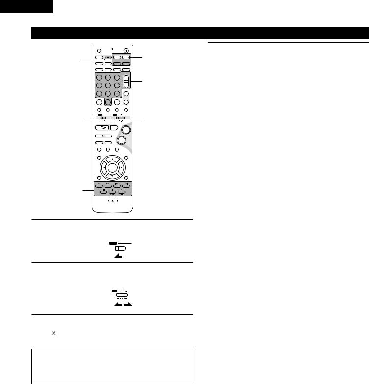
ENGLISH
(5) Operating the TV/video deck after storing its remote control signals in the preset memory
|
|
OFF |
|
|
ON |
|
|
|
|
|
VCR |
|
|
|
|
|
|
SLEEP |
REC |
TITLE |
TIME |
3-q |
|
|
|
NTSC/PAL |
|||||
|
3-w |
SOURCE |
|
TV IN |
T V |
||
|
CLEAR |
ENTER |
CHARAC. |
EDIT/MENU |
|||
|
A-B REPEAT |
SLIDE MODE |
ZOOM |
||||
|
|
|
TV CH - |
TV CH + |
|
||
|
|
PROG/DIRECT |
REPEAT |
RANDOM |
CD SRS |
|
|
|
|
SEARCH MODE |
|
||||
|
|
MODE |
MEMO |
BAND |
|
|
|
|
|
|
|
|
|
TUNING / |
|
|
|
DVD |
TUNER |
D.AUX |
TV VOL |
|
|
|
|
1 |
2 |
3 |
+ |
3-q |
|
|
|
4 |
5 |
6 |
- |
||
|
|
MD/LINE-1 |
TAPE /LINE-2 |
|
|
|
|
|
|
|
5CH STEREO |
AUTO DECODE |
TUNER |
|
|
|
|
7 |
8 |
9 |
+ |
|
|
|
|
DIRECT |
STEREO |
VIRTUAL |
CH |
|
|
|
|
CALL |
0/10 |
+10 |
- |
|
|
|
|
TEST TONE |
INPUT MODE |
SURROUND |
FUNCTION |
|
|
|
1 |
|
|
TUNER TV / VCR |
2 |
||
|
A / V |
|
DVD |
|
IN/SURR. |
||
|
|
SYSTEM |
MD |
CDR TAPE IN/SURR. |
|||
|
|
1 |
|
2 |
|
+ |
|
|
|
DVD |
|
|
|
|
|
|
|
8 |
9 |
|
|
|
|
|
|
6 |
7 |
|
- |
|
|
|
|
|
STATUS |
|
|
|
|
|
|
3 |
|
|
MUTING |
|
|
|
|
SETUP |
|
|
|
TONE /SDB |
|
|
|
|
ENTER |
|
|
|
|
|
|
CH SELECT |
|
|
|
SURROUND |
|
|
|
|
|
|
PARAMETER |
|
|
|
|
|
|
- VCR CH + |
|
||
|
3-w |
RETURN |
DISPLAY |
MENU |
TOP MENU |
|
|
|
ANGLE AUDIO |
SUB TITLE |
|
||||
|
|
|
RC-936 |
|
|
|
|
1 |
Set mode switch 1 to the “A/V” position. |
||||||
|
|
|
A / V |
|
|
|
|
 SYSTEM
3 |
Monitor TV (TV) and video deck (VCR) system buttons |
|
|
||
|
q TV system buttons |
|
|
TV |
: Power on/off |
|
0~9 |
: Channel numbers |
|
TV IN |
: TV input switching |
|
TV VOL +, – |
: Volume up/down |
|
TV CH +, – |
: Channel switching |
|
w Video deck system buttons |
|
|
VCR |
: Power on/off |
|
VCR CH +, – |
: Channel switching |
|
6, 7 |
: Manual search (fast-forward and fast-backward) |
|
1 |
: Play |
|
3 |
: Pause |
|
2 |
: Stop |
|
|
|
2 |
Set mode switch 2 to the “TV/VCR” position. |
||
|
TUNER TV / VCR |
||
|
DVD |
|
IN/SURR. |
|
MD |
|
IN/SURR. |
|
|
||
|
|
||
|
|
CDR TAPE |
|
3 |
Operate the video component. |
|
|
|
• For details, refer to the component’s operating instructions. |
|
It may not be possible to operate some models. |
|
|
NOTE:
•The TV’s “TV (POWER) and “TV IN” buttons can be operated as long as mode switch 1 is set to the “A/V” position, regardless of the position of mode switch 2.
28
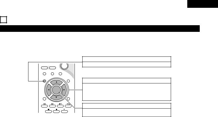
ENGLISH
10SETTING UP THE SYSTEM
(1) System setup items
•Once all connections with other AV components have been completed as described in “CONNECTIONS” (see pages 8 to 15), make the various settings described below on the monitor screen using the ADV-M71’s on-screen display function.
•Use the following buttons to set up the system:
6 |
7 |
|
- |
|
|
STATUS |
|
|
|
3 |
|
|
MUTING |
|
SETUP |
|
|
TONE /SDB |
|
|
ENTER |
|
|
|
CH SELECT |
|
|
|
SURROUND |
|
|
|
PARAMETER |
|
|
|
- VCR CH |
+ |
|
RETURN |
DISPLAY |
MENU |
TOP MENU |
|
ANGLE |
AUDIO |
|
SUB TITLE |
|
SYSTEM SETUP button
Press this to display the system setup menu.
CURSOR buttons
1 and 0:Use these to move the cursors (1 and 0) to the left and right on the screen.
•and ª: Use these to move the cursors (• and ª) to the up and down on the screen.
ENTER button
Press this to switch the display.
Also use this button to complete the setting.
System setup items and default values (set upon shipment from the factory)
|
|
Setup |
|
|
|
|
|
Default settings |
|
|
|
|
||||
|
|
|
|
|
|
|
|
|
|
|
|
|
|
|
|
|
|
Quick set up |
Set the screen size and the speaker system. |
|
|
TV Aspect |
|
|
|
|
|
|
Speaker |
|
|
||
|
|
|
|
|
|
|
|
|
|
|
|
|
|
|
||
|
|
|
4:3 PS |
|
|
|
|
2CH Virtual & SW |
||||||||
|
|
|
|
|
|
|
|
|
||||||||
|
|
|
|
|
|
|
|
|
|
|
|
|
|
|
||
|
|
Input the combination of speakers in your system and |
Front Sp. |
|
Center Sp. |
|
|
Surround Sp. |
|
Sub Woofer |
||||||
|
|
their corresponding sizes (SMALL for regular speakers, |
|
|
|
|
|
|
|
|
|
|
|
|
|
|
|
|
|
|
|
|
|
|
|
|
|
|
|
|
|
|
|
|
Speaker Configuration |
LARGE for full-size, full-range) to automatically set the |
Small |
|
|
“__” |
|
|
“__” |
|
|
|
Yes |
|||
|
|
composition of the signals output from the speakers and the |
|
|
|
|
|
|
|
|
|
|
|
|
|
|
|
|
|
|
|
|
|
|
|
|
|
|
|
|
|
|
|
|
|
frequency response. |
|
|
|
Sw Freq. = 150 Hz / SW mode = None |
|
|
||||||||
|
|
|
|
|
|
|
|
|
|
|
|
|
|
|
|
|
|
Delay Time |
This parameter is for optimizing the timing with which the |
|
Front & Subwoofer |
|
|
Center |
|
|
Surround |
||||||
Setup |
audio signals are produced from the speakers and subwoofer |
|
|
|
|
|
|
|
|
|
|
|
|
|
|
|
|
|
|
|
|
|
|
|
|
|
|
|
|
|
|||
|
according to the listening position. |
|
|
9ft (2.7m) |
|
|
|
|
“__” |
|
|
|
“__” |
|||
|
|
|
|
|
|
|
|
|
|
|
|
|
|
|
|
|
|
At the listening position, listen to the test tones output |
Front L |
|
Center |
|
Front R |
|
Surround R |
Surround L |
|
Sub Woofer |
|||||
System |
Channel Level |
|
|
|
|
|||||||||||
from the different speakers and set so that the playback |
|
|
|
|
|
|
|
|
|
|
|
|
|
|
||
|
|
|
|
|
|
|
|
|
|
|
|
|
|
|||
|
level from the different speakers is equal. |
0 dB |
|
“__” |
|
0 dB |
|
|
“__” |
|
“__” |
|
0 dB |
|||
|
|
|
|
|
|
|
|
|
|
|
|
|
|
|
|
|
|
DVD auto power off setting |
The power automatically switches to standby if no |
|
|
|
|
|
|
|
|
|
|
|
|
|
|
|
operation is performed for 30 minutes while in the stop |
|
|
|
power does not turn off automatically |
|
|
|||||||||
|
|
mode with the function set to DVD. |
|
|
|
|
|
|
|
|
|
|
|
|
|
|
|
|
|
|
|
|
|
|
|
|
|
|
|
|
|
|
|
|
Function Setting |
Set the LINE-1 and LINE-2 function names and turn the |
|
LINE-1 |
|
|
|
LINE-2 |
|
|
REC OUT |
|||||
|
|
|
|
|
|
|
|
|
|
|
|
|
|
|
||
|
analog recording output (REC OUT) on or off. |
|
MD |
|
|
|
TAPE |
|
|
|
ON |
|||||
|
|
|
|
|
|
|
|
|
||||||||
|
|
|
|
|
|
|
|
|
|
|||||||
|
|
|
|
|
|
|
|
|
|
|
|
|
|
|
||
|
Disc Setup |
Set the audio language, subtitle language and disc menu |
|
Dialog |
|
|
Subtitle |
|
|
Disc Menu |
||||||
|
|
|
|
|
|
|
|
|
|
|
|
|
|
|
||
|
language for when playing discs. |
|
English |
|
|
|
OFF |
|
|
English |
||||||
|
|
|
|
|
|
|
|
|||||||||
|
|
|
|
|
|
|
|
|
||||||||
|
|
|
|
|
|
|
|
|
|
|
|
|
|
|
||
|
OSD Setup |
Set the wallpaper for the setup and operation screens. |
|
|
|
|
|
Wall Paper |
|
|
|
|
||||
|
|
|
|
|
|
|
|
|
|
|
|
|
|
|
||
|
|
|
|
|
|
|
|
Blue |
|
|
|
|
||||
|
|
|
|
|
|
|
|
|
|
|
|
|
|
|||
|
|
|
|
|
|
|
|
|
|
|
||||||
|
Video Setup |
Set the screen size and video system for the TV being used. |
TV Aspect |
|
TV Type |
|
|
Video Mode |
|
|
Black level |
|||||
Setup |
|
|
|
|
|
|
|
|
|
|
|
|
|
|
||
4 : 3 PS |
|
|
NTSC |
|
|
AUTO |
|
|
LIGHTER |
|||||||
|
|
|
|
|
|
|
|
|||||||||
|
|
|
|
|
|
|
|
|
|
|
|
|
|
|
|
|
DVD |
Audio Setup |
Set the digital audio signal format and the linear PCM |
|
|
Digital Out |
|
|
|
|
|
LPCM Select |
|||||
|
|
|
|
|
|
|
|
|
|
|
|
|
|
|||
|
sampling frequency and bit conversion. |
|
|
Normal |
|
|
|
|
|
|
OFF |
|
|
|||
|
|
|
|
|
|
|
|
|
|
|
|
|||||
|
|
|
|
|
|
|
|
|
|
|
|
|
||||
|
|
|
|
|
|
|
|
|
|
|
|
|
|
|||
|
Ratings |
Make the playback restriction setting for DVDs with |
|
|
Rating Level |
|
|
Pass Word Change |
||||||||
|
restricted viewing and set the password required for |
|
|
|
|
|
|
|
|
|
|
|
|
|
|
|
|
|
|
|
|
|
|
|
|
|
|
|
|
|
|
||
|
|
changing the setting. |
|
|
No Limit |
|
|
|
|
|
0000 (Default) |
|||||
|
|
|
|
|
|
|
|
|
|
|
|
|
|
|
||
|
Other Setup |
Make the closed caption setting for DVDs. (A commercially |
|
Closed Caption |
|
|
|
Slide Show |
|
|
||||||
|
|
|
|
|
|
|
|
|
|
|
|
|
|
|
||
|
available decoder is required to display the closed captions.) |
|
|
OFF |
|
|
|
|
|
|
5SEC |
|
|
|||
|
|
|
|
|
|
|
|
|
|
|
|
|||||
|
|
|
|
|
|
|
|
|
|
|
|
|
||||
|
|
|
|
|
|
|
|
|
|
|
|
|
|
|
|
|
29
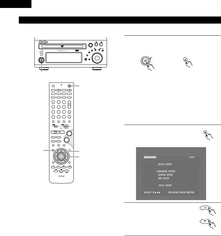
ENGLISH
(2) Quick setup procedure
•Refer to “Connections” (pages 8 to 15) and check that all the connections are correct.
DVD SURROUND RECEIVER ADV-M71 |
SURROUND / SELECT |
PUSH - PARAM. |
|
- + |
MENU / SET |
BAND |
TONE / SDB |
VOLUME |
FUNCTION |
|
ON / STANDBY |
|
PHONES |
|
1
OFF |
|
ON |
1 |
|
|
VCR |
|
|
|
SLEEP |
REC |
TITLE |
TIME |
|
NTSC/PAL |
|
|||
SOURCE |
|
TV IN |
T V |
|
CLEAR |
ENTER |
CHARAC. |
EDIT/MENU |
|
A-B REPEAT |
SLIDE MODE |
ZOOM |
|
|
|
|
TV CH - |
TV CH + |
|
PROG/DIRECT |
REPEAT |
RANDOM |
CD SRS |
|
SEARCH MODE |
|
|||
MODE |
MEMO |
BAND |
|
|
|
|
|
TUNING / |
|
DVD |
TUNER |
D.AUX |
TV VOL |
|
1 |
2 |
3 |
+ |
|
MD/LINE-1 |
TAPE /LINE-2 |
|
- |
|
4 |
5 |
6 |
|
|
|
5CH STEREO |
AUTO DECODE |
TUNER |
|
7 |
8 |
9 |
+ |
|
DIRECT |
STEREO |
VIRTUAL |
CH |
|
CALL |
0/10 |
+10 |
- |
|
TEST TONE |
INPUT MODE |
SURROUND |
FUNCTION |
|
|
|
TUNER TV / VCR |
|
|
A / V |
|
DVD |
IN/SURR. |
|
|
SYSTEM |
MD |
IN/SURR. |
|
|
|
CDR TAPE |
|
|
1 |
|
2 |
+ |
|
DVD |
|
|
|
|
8 |
9 |
|
|
|
|
|
- |
|
|
67
STATUS
3MUTING
2,12 |
SETUP |
|
TONE /SDB |
|
|
4,6,8,11 |
|
|
|
|
|
|
|
ENTER |
3,5,7,9,10 |
|
CH SELECT |
|
SURROUND |
|
|
PARAMETER |
|
|
|
|
- VCR CH + |
|
RETURN |
DISPLAY |
MENU TOP MENU |
|
ANGLE |
AUDIO |
SUB TITLE |
RC-936
Turn on the power.
1 • The power indicator (LED) lights green, the power turns on and the display lights.
ON / STANDBY
Green
|
ON |
Main unit |
Remote control unit |

 Several seconds are required from the time the power button is pressed until the power turns on. This is due to the built-in muting circuit that turns off (mutes) the sound when the power is turned on and off. The power indicator flashes green while the muting circuit is activated.

 Even when the power button has been pressed again and the power has been set to the standby mode, power is still supplied to some circuits. When leaving home or traveling, be sure to unplug the power cord from the power outlet. In the standby mode, the power indicator is lit red. The indicator is orange when the timer is set.
2 |
Press the SETUP button to display the |
SETUP |
setup screen. |
|
|
|
|
Remote control unit
3 |
Use the • and ª cursor buttons to |
|
|
|
select “Quick System Setup”. |
|
• The selected item is displayed in |
|
yellow. |
Remote control unit
30
 Loading...