


 Loading...


Preface
Thank you for choosing DELTA’s high-performance VFD-VE Series. The VFD-VE Series is manufactured with high-quality components and materials and incorporates the latest microprocessor technology available.
This manual is to be used for the installation, parameter setting, troubleshooting, and daily maintenance of the AC motor drive. To guarantee safe operation of the equipment, read the following safety guidelines before connecting power to the AC motor drive. Keep this operating manual at hand and distribute to all users for reference.
To ensure the safety of operators and equipment, only qualified personnel familiar with AC motor drive are to do installation, start-up and maintenance. Always read this manual thoroughly before using VFD-VE series AC Motor Drive, especially the WARNING, DANGER and CAUTION notes.
Failure to comply may result in personal injury and equipment damage. If you have any questions, please contact your dealer.
PLEASE READ PRIOR TO INSTALLATION FOR SAFETY.
 DANGER!
1.AC input power must be disconnected before any wiring to the AC motor drive is made.
2.A charge may still remain in the DC-link capacitors with hazardous voltages, even if the power has been turned off. To prevent personal injury, please ensure that power has turned off before opening the AC motor drive and wait ten minutes for the capacitors to discharge to safe voltage levels.
3.Never reassemble internal components or wiring.
4.The AC motor drive may be destroyed beyond repair if incorrect cables are connected to the input/output terminals. Never connect the AC motor drive output terminals U/T1, V/T2, and W/T3 directly to the AC mains circuit power supply.
5.Ground the VFD-VE using the ground terminal. The grounding method must comply with the laws of the country where the AC motor drive is to be installed. Refer to the Basic Wiring Diagram.
6.VFD-VE series is used only to control variable speed of 3-phase induction motors, NOT for 1- phase motors or other purpose.
7.VFD-VE series shall NOT be used for life support equipment or any life safety situation.

 WARNING!
1.DO NOT use Hi-pot test for internal components. The semi-conductor used in AC motor drive easily damage by high-voltage.
2.There are highly sensitive MOS components on the printed circuit boards. These components are especially sensitive to static electricity. To prevent damage to these components, do not touch these components or the circuit boards with metal objects or your bare hands.
3.Only qualified persons are allowed to install, wire and maintain AC motor drives.
 CAUTION!
1.Some parameters settings can cause the motor to run immediately after applying power.
2.DO NOT install the AC motor drive in a place subjected to high temperature, direct sunlight, high humidity, excessive vibration, corrosive gases or liquids, or airborne dust or metallic particles.
3.Only use AC motor drives within specification. Failure to comply may result in fire, explosion or electric shock.
4.To prevent personal injury, please keep children and unqualified people away from the equipment.
5.When the motor cable between AC motor drive and motor is too long, the layer insulation of the motor may be damaged. Please use a frequency inverter duty motor or add an AC output reactor to prevent damage to the motor. Refer to appendix B Reactor for details.
6.The rated voltage for AC motor drive must be ≤ 240V (≤ 480V for 460V models) and the mains supply current capacity must be ≤ 5000A RMS (≤10000A RMS for the ≥ 40hp (30kW) models).

Table of Contents
Preface ............................................................................................................. |
i |
|
Table of Contents .......................................................................................... |
iii |
|
Chapter 1 Introduction................................................................................ |
1-1 |
|
1.1 |
Receiving and Inspection ................................................................... |
1-2 |
1.1.1 Nameplate Information................................................................ |
1-2 |
|
1.1.2 Model Explanation ...................................................................... |
1-2 |
|
1.1.3 Series Number Explanation ........................................................ |
1-3 |
|
1.1.4 Drive Frames and Appearances ................................................. |
1-3 |
|
1.2 |
Preparation for Installation and Wiring ............................................... |
1-4 |
1.2.1 Ambient Conditions..................................................................... |
1-4 |
|
1.2.2 Remove Keypad ......................................................................... |
1-6 |
|
1.2.3 Remove Front Cover................................................................... |
1-7 |
|
1.2.4 Lifting .......................................................................................... |
1-8 |
|
1.3 |
Dimensions......................................................................................... |
1-9 |
Chapter 2 Installation and Wiring .............................................................. |
2-1 |
|
2.1 |
Wiring ................................................................................................. |
2-2 |
2.2 |
External Wiring ................................................................................... |
2-4 |
2.3 |
Main Circuit ........................................................................................ |
2-5 |
2.3.1 Main Circuit Connection.............................................................. |
2-5 |
|
2.3.2 Main Circuit Terminals ................................................................ |
2-9 |
|
2.4 |
Control Terminals ............................................................................. |
2-10 |
Chapter 3 Digital Keypad Operation and Start Up .................................... |
3-1 |
|
3.1 |
Digital Keypad KPV-CE01 .................................................................. |
3-1 |
3.1.1 Description of the Digital Keypad KPV-CE01 .............................. |
3-1 |
|
3.1.2 How to Operate the Digital Keypad KPV-CE01........................... |
3-3 |
|
3.1.3 Dimension of the Digital Keypad ................................................. |
3-5 |
|
3.1.4 Reference Table for the LCD Display of the Digital Keypad........ |
3-5 |
|
3.1.5 Operation Method........................................................................ |
3-6 |
|
3.2 |
Start-up............................................................................................... |
3-6 |
3.2.1 Preparations before Start-up ....................................................... |
3-6 |
|
3.2.2 Trial Run...................................................................................... |
3-8 |
|
Chapter 4 Parameters.................................................................................. |
4-1 |
|
4.1 |
Summary of Parameter Settings......................................................... |
4-2 |
4.2 |
Version Differences .......................................................................... |
4-26 |
4.2.1 Version 2.02 .............................................................................. |
4-26 |
|
4.2.2 Version 2.04 .............................................................................. |
4-26 |
|
4.3 |
Description of Parameter Settings .................................................... |
4-38 |
Chapter 5 Troubleshooting ......................................................................... |
5-1 |
|
5.1 |
Over Current (OC) .............................................................................. |
5-1 |
5.2 |
Ground Fault....................................................................................... |
5-2 |
5.3 |
Over Voltage (OV) .............................................................................. |
5-2 |
5.4 |
Low Voltage (Lv)................................................................................. |
5-3 |
5.5 |
Over Heat (oH1, oH2, oH3) ................................................................ |
5-4 |
5.6 |
Overload ............................................................................................. |
5-4 |
5.7 |
Display of KPV-CE01 is Abnormal...................................................... |
5-5 |
5.8 Phase Loss (PHL) .............................................................................. |
5-5 |
|
5.9 Motor cannot Run............................................................................... |
5-6 |
|
5.10 |
Motor Speed cannot be Changed..................................................... |
5-7 |
5.11 |
Motor Stalls during Acceleration....................................................... |
5-8 |
5.12 |
The Motor does not Run as Expected .............................................. |
5-8 |
5.13 |
Electromagnetic/Induction Noise ...................................................... |
5-9 |
5.14 |
Environmental Condition .................................................................. |
5-9 |
5.15 |
Affecting Other Machines ............................................................... |
5-10 |
Chapter 6 Fault Code Information and Maintenance................................ |
6-1 |
|
6.1 Fault Code Information....................................................................... |
6-1 |
|
6.1.1 Common Problems and Solutions............................................... |
6-1 |
|
6.1.2 Reset .......................................................................................... |
6-6 |
|
6.2 Maintenance and Inspections............................................................. |
6-7 |
|
Appendix A Specifications ........................................................................ |
A-1 |
|
Appendix B Accessories ........................................................................... |
B-1 |
|
B.1 All Brake Resistors & Brake Units Used in AC Motor Drives.............. |
B-1 |
|
B.1.1 Dimensions and Weights for Brake Resistors ............................ |
B-4 |
|
B.1.2 Specifications for Brake Unit ...................................................... |
B-6 |
|
B.1.3 Dimensions for Brake Unit.......................................................... |
B-7 |
|
B.2 No-fuse Circuit Breaker Chart ............................................................ |
B-9 |
|
B.3 Fuse Specification Chart .................................................................. |
B-10 |
|
B.4 AC Reactor ...................................................................................... |
B-11 |
|
B.4.1 AC Input Reactor Recommended Value................................... |
B-11 |
|
B.4.2 AC Output Reactor Recommended Value................................ |
B-11 |
|
B.4.3 Applications for AC Reactor...................................................... |
B-13 |
|
B.5 |
Zero Phase Reactor (RF220X00A) ................................................. |
B-15 |
B.6 DC Choke Recommended Values................................................... |
B-16 |
|
B.7 |
Remote Controller RC-01 ................................................................ |
B-17 |
B.8 |
PG Card (for Encoder) .................................................................... |
B-18 |
B.8.1 EMV-PG01X ............................................................................. |
B-18 |
|
B.8.2 EMV-PG01O............................................................................. |
B-21 |
|
B.8.3 EMV-PG01L.............................................................................. |
B-25 |
|
B.9 |
AMD-EMI Filter Cross Reference .................................................... |
B-29 |
B.9.1 Dimensions ............................................................................... |
B-33 |
|
B.10 Multi-function I/O Extension Card.................................................. |
B-40 |
|
B.10.1 Functions ................................................................................ |
B-40 |
|
B.10.2 Dimensions ............................................................................. |
B-42 |
|
B.10.3 Wiring...................................................................................... |
B-42 |
|
Appendix C How to Select the Right AC Motor Drive.............................. |
C-1 |
|
C.1 Capacity Formulas ............................................................................ |
C-1 |
|
C.2 General Precaution ........................................................................... |
C-3 |
|
C.3 How to Choose a Suitable Motor....................................................... |
C-5 |
|

Chapter 1 Introduction
The AC motor drive should be kept in the shipping carton or crate before installation. In order to retain the warranty coverage, the AC motor drive should be stored properly when it is not to be used for an extended period of time. Storage conditions are:
 CAUTION!
1.Store in a clean and dry location free from direct sunlight or corrosive fumes.
2.Store within an ambient temperature range of -10 °C to +40 °C.
3.Store within a relative humidity range of 0% to 90% and non-condensing environment.
4.Store within an air pressure range of 86 kPA to 106kPA.
5.DO NOT place on the ground directly. It should be stored properly. Moreover, if the surrounding environment is humid, you should put exsiccator in the package.
6.DO NOT store in an area with rapid changes in temperature. It may cause condensation and frost.
7.If the AC motor drive is stored for more than 3 months, the temperature should not be higher than 30 °C. Storage longer than one year is not recommended, it could result in the degradation of the electrolytic capacitors.
8.When the AC motor drive is not used for longer time after installation on building sites or places with humidity and dust, it’s best to move the AC motor drive to an environment as stated above.
Revision August 2008, 03VE, SW V2.04 |
1-1 |
Chapter 1 Introduction|
1.1 Receiving and Inspection
This VFD-VE AC motor drive has gone through rigorous quality control tests at the factory before shipment. After receiving the AC motor drive, please check for the following:
Check to make sure that the package includes an AC motor drive, the User Manual/Quick Start and CD.
Inspect the unit to assure it was not damaged during shipment.
Make sure that the part number indicated on the nameplate corresponds with the part number of your order.
1.1.1 Nameplate Information
Example for 5HP/3.7kW 3-phase 230V AC motor drive
AC Drive Model |
|
|
MODE |
|
|
|
|
: VFD037V23A-2 |
|||||||||||||||||||||||||||||||||
|
|
|
|
|
|
||||||||||||||||||||||||||||||||||||
|
|||||||||||||||||||||||||||||||||||||||||
Input Spec. |
|
|
|
INPUT |
|
|
|
|
: 3PH 200-240V 50/60Hz 19.6A |
||||||||||||||||||||||||||||||||
Output Spec. |
|
|
OUTPUT |
|
|
|
|
: 3PH 0-240V 17A 6.5kVA 5HP |
|||||||||||||||||||||||||||||||||
|
|
Freq. Range : 0.00~600.00Hz |
|||||||||||||||||||||||||||||||||||||||
Output Frequency Range |
|
|
|
||||||||||||||||||||||||||||||||||||||
|
|
|
ENCLOSURE: TYPE 1 |
||||||||||||||||||||||||||||||||||||||
|
|
||||||||||||||||||||||||||||||||||||||||
Enclosure type |
|
|
|
|
|
|
|
|
|
|
|
|
|
|
|
|
|
|
|
|
|
|
|
|
|
|
|
|
|
|
|
|
|
|
|
|
|
|
|
|
|
|
|
|
|
|
|
|
|
|
|
|
|
|
|
|
|
|
|
|
|
|
|
|
|
|
|
|
|
|
|
|
|
|
|
|
|
|
|
|
|
|
|
|
|
|
|
|
|
|
|
|
|
|
|
|
|
|
|
|
|
|
|
|
|
|
|
|
|
|
|
|
|
|
|
|
|
|
|
|
|
|
|
|
|
Serial Number & Bar Code |
|
|
|
|
|
|
|
|
|
|
|
037V23A2T6360001 |
|
||||||||||||||||||||||||||||
|
|
|
|
|
|
|
|
|
|
|
|
|
|
|
|
|
|
|
|
|
|
|
|
|
|
|
|
|
|
|
|
|
|
|
|
|
|
|
|
|
|
1.1.2 Model Explanation
VFD 037 V 23 A-2 VFD-VE Series Version Type Mains Input Voltage
23:230V Three phase 43:460V Three phase Vector Series
Applicable motor capacity
007: 1 HP(0.7kW) |
150: 20HP(15kW) |
022: 3 HP(2.2kW) |
220: 30 HP(22kW) |
037: 5 HP(3.7kW) |
300: 40HP(30kW) |
055: 7.5HP(5.5kW) |
370: 50 HP(37kW) |
075: 10 HP(7.5kW) |
450: 60HP(45kW) |
110: 15 HP(11kW) |
550: 75HP(55kW) |
|
750: 100HP(75kW) |
Series Name (Variable Frequency Drive)
1-2 |
Revision August 2008, 03VE, SW V2.04 |
Chapter 1 Introduction|
1.1.3Series Number Explanation
037V23A2 T 7 36 


Production number
Production week
Production year 2007
Production factory
(T: Taoyuan, W: Wujian)
230V 3-phase 5HP(3.7kW)
Model
If the nameplate information does not correspond to your purchase order or if there are any problems, please contact your distributor.
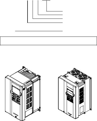
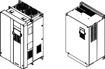
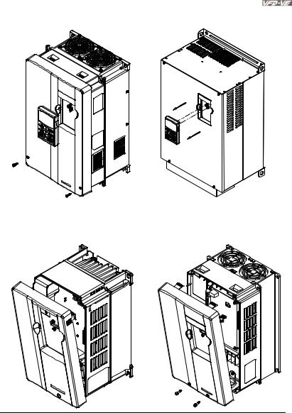
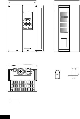
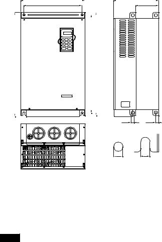
1.1.4 Drive Frames and Appearances
1-5HP/0.75-3.7kW (Frame B) |
7.5-15HP/5.5-11kW (Frame C) |
|
|
|
|
Revision August 2008, 03VE, SW V2.04 |
1-3 |
Chapter 1 Introduction|
15-30HP/11-22kW (Frame D) |
40-100HP/30-75kW (Frame E) |
|
|
|
|
|
Frame |
Power range |
Models |
|
B (B1) |
1-3hp (0.75-2.2kW) |
VFD007V23A/43A-2, VFD015V23A/43A-2, |
|
VFD022V23A/43A-2 |
||
|
|
|
|
|
B (B2) |
5hp (3.7kW) |
VFD037V23A/43A-2 |
|
C |
7.5-15hp (5.5-11kW) |
VFD055V23A/43A-2, VFD075V23A/43A-2, VFD110V43B-2 |
|
D |
15-30hp (11-22kW) |
VFD110V23A/43A-2, VFD150V23A/43A-2, |
|
VFD185V23A/43A-2, VFD220V23A/43A-2 |
||
|
|
|
|
|
E (E1) |
40-60hp (30-45kW) |
VFD300V43A-2, VFD370V43A-2, VFD450V43A-2 |
|
E (E2) |
40-100hp (30-75kW) |
VFD300V23A-2, VFD370V23A-2, VFD550V43C-2, |
|
VFD750V43C-2 |
||
|
|
|
Please refer to Chapter 1.3 for exact dimensions.
1.2 Preparation for Installation and Wiring
1.2.1 Ambient Conditions
Install the AC motor drive in an environment with the following conditions:
1-4 |
Revision August 2008, 03VE, SW V2.04 |
|
|
|
Chapter 1 Introduction| |
|
|
Air Temperature: |
|
-10 ~ +40°C (14 ~ 122°F) |
|
|
Relative Humidity: |
<90%, no condensation allowed |
||
Operation |
Atmosphere |
|
86 ~ 106 kPa |
|
pressure: |
|
|
||
|
Installation Site |
|
<1000m |
|
|
Altitude: |
|
|
|
|
|
<20Hz: 9.80 m/s2 (1G) max |
|
|
|
Vibration: |
|
|
|
|
|
20 ~ 50Hz: 5.88 m/s2 (0.6G) max |
||
|
Temperature: |
|
-20°C ~ +60°C (-4°F ~ 140°F) |
|
Storage |
Relative Humidity: |
<90%, no condensation allowed |
||
Atmosphere |
|
|
|
|
Transportation |
|
86 ~ 106 kPa |
|
|
|
pressure: |
|
|
|
|
|
<20Hz: 9.80 m/s2 (1G) max |
|
|
|
Vibration: |
|
|
|
|
|
20 ~ 50Hz: 5.88 m/s2 (0.6G) max |
||
Pollution Degree |
2: good for a factory type environment. |
|
||
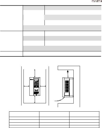
Minimum Mounting Clearances |
|
|
|
|
|
H |
|
Air Flow |
|
|
|
|
|
|
|
W |
W |
|
|
|
H |
|
|
|
|
HP |
|
W |
H |
|
|
mm (inch) |
mm (inch) |
|
|
|
|
||
|
1-5HP |
|
50 (2) |
150 (6) |
7.5-20HP |
|
75 (3) |
175 (7) |
|
25-75HP |
|
75 (3) |
200 (8) |
|
100HP and above |
|
75 (3) |
250 (10) |
|
Revision August 2008, 03VE, SW V2.04 |
1-5 |
Chapter 1 Introduction|
 CAUTION!
1.Operating, storing or transporting the AC motor drive outside these conditions may cause damage to the AC motor drive.
2.Failure to observe these precautions may void the warranty!
3.Mount the AC motor drive vertically on a flat vertical surface object by screws. Other directions are not allowed.
4.The AC motor drive will generate heat during operation. Allow sufficient space around the unit for heat dissipation.
5.The heat sink temperature may rise to 90°C when running. The material on which the AC motor drive is mounted must be noncombustible and be able to withstand this high temperature.
6.When AC motor drive is installed in a confined space (e.g. cabinet), the surrounding temperature must be within -10 ~ 40°C with good ventilation. DO NOT install the AC motor drive in a space with bad ventilation.
7.When installing multiple AC more drives in the same cabinet, they should be adjacent in a row with enough space in-between. When installing one AC motor drive below another one, use a metal separation between the AC motor drives to prevent mutual heating.
8.Prevent fiber particles, scraps of paper, saw dust, metal particles, etc. from adhering to the heatsink.
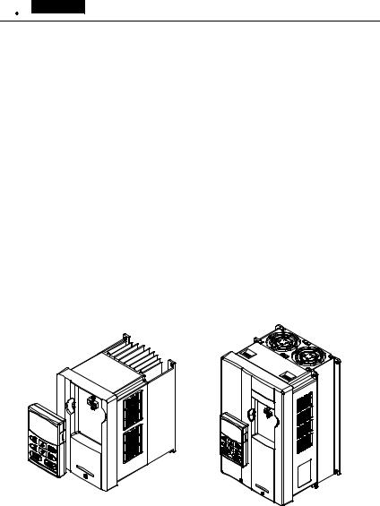
1.2.2 Remove Keypad
1-5HP/0.75-3.7kW (Frame B) |
7.5-15HP/5.5-11kW (Frame C) |
|
|
|
|
1-6 |
Revision August 2008, 03VE, SW V2.04 |
|
Chapter 1 Introduction| |
15-30HP/11-22kW (Frame D) |
40-100HP/30-75kW (Frame E) |
|
|
|
|
1.2.3 Remove Front Cover
1-5HP/0.75-3.7kW (Frame B) |
7.5-15HP/5.5-11kW (Frame C) |
|
|
Revision August 2008, 03VE, SW V2.04 |
1-7 |
Chapter 1 Introduction|
15-30HP/11-22kW (Frame D) |
40-100HP/30-75kW (Frame E) |
|
|
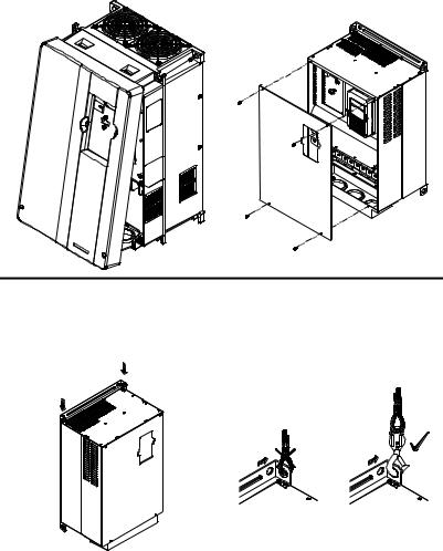
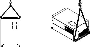
1.2.4 Lifting
Please carry only fully assembled AC motor drives as shown in the following.
For 40-100HP (Frame E and E1)
Step 1 |
Step 2 |
|
|
|
|
1-8 |
Revision August 2008, 03VE, SW V2.04 |
Chapter 1 Introduction|
Step 3 |
Step 4 |
||||||||
|
|
|
|
|
|
|
|
|
|
|
|
|
|
|
|
|
|
|
|
|
|
|
|
|
|
|
|
|
|
|
|
|
|
|
|
|
|
|
|
|
|
|
|
|
|
|
|
|
|
|
|
|
|
|
|
|
|
|
|
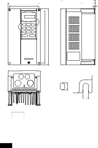
1.3 Dimensions
Revision August 2008, 03VE, SW V2.04 |
1-9 |
Chapter 1 Introduction|
Frame B
|
|
|
|
|
|
D |
||||
W |
|
|
|
|
|
|
D1 |
|||
W1 |
|
|
|
|
|
|
D2 |
|||
|
|
|
|
|
|
|
|
|
|
|
|
|
|
|
|
|
|
|
|
|
|
H
H1
S1
S2
Unit: mm[inch] |
|
|
|
|
|
|
|
|
|
|
Frame |
W |
W1 |
|
H |
H1 |
D |
D1 |
D2 |
S1 |
S2 |
B1 |
150.0 |
135.0 |
|
260.0 |
244.3 |
160.2 |
67.0 |
4.0 |
8.0 |
6.5 |
[5.91] |
[5.32] |
|
[10.24] |
[9.63] |
[6.31] |
[2.64] |
[0.16] |
[0.32] |
[0.26] |
|
|
|
|||||||||
|
|
|
|
|
|
|
|
|
|
|
B2 |
150.0 |
135.0 |
|
272.1 |
244.3 |
183.7 |
67.0 |
4.0 |
8.0 |
6.5 |
[5.91] |
[5.32] |
|
[10.72] |
[9.63] |
[7.24] |
[2.64] |
[0.16] |
[0.32] |
[0.26] |
|
|
|
|||||||||
|
|
|
|
|
|
|
|
|
|
|


 NOTE
NOTE
Frame B1: VFD007V23A/43A-2, VFD015V23A/43A-2, VFD022V23A/43A-2
Frame B2: VFD037V23A/43A-2
1-10 |
Revision August 2008, 03VE, SW V2.04 |
Chapter 1 Introduction|
Frame C
W |
|
|
D |
|
W1 |
|
|
|
|
|
|
|
|
|
|
|
|
|
|
H
H1
S1 |
S2 |
Unit: mm[inch] |
|
|
|
|
|
|
|
|
|
|
Frame |
W |
W1 |
|
H |
H1 |
D |
- |
- |
S1 |
S2 |
C |
200.0 |
185.6 |
|
323.0 |
244.3 |
160.2 |
- |
- |
7.0 |
7.0 |
[7.88] |
[7.31] |
|
[12.73] |
[9.63] |
[6.31] |
[0.28] |
[0.28] |
|||
|
|
|
|
|||||||
|
|
|
|
|
|
|
|
|
|
|


 NOTE
NOTE
Frame C: VFD055V23A/43A-2, VFD075V23A/43A-2, VFD110V43B-2
Revision August 2008, 03VE, SW V2.04 |
1-11 |
Chapter 1 Introduction|
Frame D
W |
|
|
|
D |
|
|||||
|
|
|
|
D1 |
|
|||||
W1 |
|
|
|
|
D2 |
|
||||
|
|
|
|
|
|
|
|
|
|
|
|
|
|
|
|
|
|
|
|
|
|
H
H1
S1
Unit: mm[inch] |
|
|
|
|
|
|
|
|
|
|
Frame |
W |
W1 |
|
H |
H1 |
D |
D1 |
D2 |
S1 |
- |
D |
250.0 |
226.0 |
|
408.2 |
384.0 |
205.4 |
110.0 |
10.0 |
10.0 |
- |
[9.85] |
[8.90] |
|
[16.07] |
[15.13] |
[8.08] |
[4.33] |
[0.39] |
[0.39] |
||
|
|
|
||||||||
|
|
|
|
|
|
|
|
|
|
|


 NOTE
NOTE
Frame D: VFD110V23A/43A-2, VFD150V23A/43A-2, VFD185V23A/43A-2, VFD220V23A/43A-2
1-12 |
Revision August 2008, 03VE, SW V2.04 |
Chapter 1 Introduction|
Frame E
W |
|
|
|
D |
W1 |
|
|
D1 |
|
|
|
|
|
|
|
|
|
|
|
|
|
|
H |
|
|
|
H2 |
|
H1 |
|
|
|
|
|||||
|
|
|
|
|
|
|
|
|
|
|
|
|
|
|
|
|
|
|
|
|
|
|
|
|
|
|
|
|
|
|
|
S3 D2
S1 S2
Unit: mm[inch]
Frame |
W |
W1 |
H |
H1 |
H2 |
D |
D1 |
D2 |
S1 |
S2 |
S3 |
|
E1 |
370.0 |
335.0 |
- |
589.0 |
560.0 |
260.0 |
132.5 |
18.0 |
13.0 |
13.0 |
18.0 |
|
[14.57] |
[13.19] |
[23.19] |
[22.05] |
[10.24] |
[5.22] |
[0.71] |
[0.51] |
[0.51] |
[0.71] |
|||
|
|
|||||||||||
|
|
|
|
|
|
|
|
|
|
|
|
|
E2 |
370.0 |
335.0 |
595.0 |
589.0 |
560.0 |
260.0 |
132.5 |
18.0 |
13.0 |
13.0 |
18.0 |
|
[14.57] |
[13.19] |
[23.43] |
[23.19] |
[22.05] |
[10.24] |
[5.22] |
[0.71] |
[0.51] |
[0.51] |
[0.71] |
||
|
||||||||||||
|
|
|
|
|
|
|
|
|
|
|
|


 NOTE
NOTE
Frame E1: VFD300V43A-2, VFD370V43A-2, VFD450V43A-2
Frame E2: VFD300V23A-2, VFD370V23A-2, VFD550V43C-2, VFD750V43C-2
Revision August 2008, 03VE, SW V2.04 |
1-13 |
Chapter 1 Introduction|
This page intentionally left blank
1-14 |
Revision August 2008, 03VE, SW V2.04 |

Chapter 2 Installation and Wiring
After removing the front cover (see chapter 1.2.3 for details), check if the power and control terminals are clear. Be sure to observe the following precautions when wiring.
General Wiring Information
Applicable Codes
All VFD-VE series are Underwriters Laboratories, Inc. (UL) and Canadian Underwriters Laboratories (cUL) listed, and therefore comply with the requirements of the National Electrical Code (NEC) and the Canadian Electrical Code (CEC).
Installation intended to meet the UL and cUL requirements must follow the instructions provided in “Wiring Notes” as a minimum standard. Follow all local codes that exceed UL and cUL requirements. Refer to the technical data label affixed to the AC motor drive and the motor nameplate for electrical data.
The "Line Fuse Specification" in Appendix B, lists the recommended fuse part number for each VFD-VE Series part number. These fuses (or equivalent) must be used on all installations where compliance with U.L. standards is a required.
 CAUTION!
1.Make sure that power is only applied to the R/L1, S/L2, T/L3 terminals. Failure to comply may result in damage to the equipment. The voltage and current should lie within the range as indicated on the nameplate.
2.Check following items after finishing the wiring:
A.Are all connections correct?
B.No loose wires?
C.No short-circuits between terminals or to ground?
 DANGER!
1.A charge may still remain in the DC bus capacitors with hazardous voltages even if the power has been turned off. To prevent personal injury, please ensure that the power is turned off and wait ten minutes for the capacitors to discharge to safe voltage levels before opening the AC motor drive.
2.All the units must be grounded directly to a common ground terminal to prevent lightning strike or electric shock.
3.Only qualified personnel familiar with AC motor drives is allowed to perform installation, wiring and commissioning.
4.Make sure that the power is off before doing any wiring to prevent electric shock.
Revision August 2008, 03VE, SW V2.04 |
2-1 |
Chapter 2 Installation and Wiring|
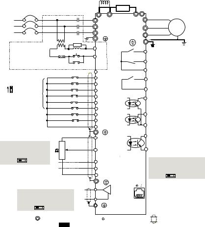
2.1 Wiring
Users must connect wires according to the circuit diagrams on the following pages. Do not plug a modem or telephone line to the RS-485 communication port or permanent damage may result. The pins 1 & 2 are the power supply for the optional copy keypad KPV-CE01 only and should not be used
for RS-485 communication.
Figure 1 for models of VFD-VE Series (15 HP/11kW and below)
VFD007V23A/43A-2, VFD015V23A/43A-2, VFD022V23A/43A-2, VFD037V23A/43A-2, VFD055V23A/43A-2, VFD075V23A/43A-2, VFD110V43B-2, VFD110V23A/43A-2
DC choke
(optional) Brak e res istor
|
|
|
|
|
|
|
|
|
(optional) |
|
|
|
|
|
Fus e/NFB(No Fuse B reaker) |
Jumper |
|
|
|
|
|||||
|
|
|
+1 |
+2/B1 B2 |
- |
|
Motor |
|||||
R(L1) |
|
|
|
|
|
|
|
|
||||
|
|
|
|
|
|
|
R(L1) |
U(T1) |
|
IM |
||
S(L2) |
|
|
|
|
|
|
|
S(L2) |
V(T2) |
|
||
T(L3) |
|
|
|
|
|
|
|
T(L3) |
W(T3) |
|
3~ |
|
|
|
|
|
|
|
|
|
E |
|
E |
|
|
Recommended Circuit |
|
|
SA |
|
|
|
|
|||||
|
|
|
|
|
|
|
||||||
when power s uppl y |
|
|
|
RB |
|
RA |
|
|
||||
|
|
|
MC |
|
|
|
||||||
is turned O FF by a |
|
|
|
|
|
|
||||||
fault output. |
|
|
|
|
RC |
|
RB |
|
|
|||
If the fault occurs, the |
|
OFF |
ON |
|
|
Multi-function c ontact output 1 |
||||||
contact will be O N to turn |
|
MC |
|
|
|
(r elay) |
|
|||||
off the power and protect the power sy stem. |
+24V |
|
RC |
factory setti ng: fault indi cation |
||||||||
Factory setting: |
|
FWD/STOP |
|
|
MRA |
|
|
|||||
|
|
FWD |
|
Multi-function c ontact output 2 |
||||||||
SINK Mode |
|
|
REV/STO P |
|
|
|
||||||
|
|
|
REV |
|
|
(relay) |
|
|||||
Sink |
|
|
|
|
Multi-s tep 1 |
|
MRC |
48VDC 50mA |
||||
Sw1 |
|
|
|
|
MI1 |
|||||||
|
Fac tory |
|
|
|
|
|
|
factory setti ng: |
||||
Source |
|
|
Multi-s tep 2 |
|
MI2 |
MO1 |
|
indicates that i t is running |
||||
|
setting |
|
|
|
||||||||
Please refer to |
|
Multi-s tep 3 |
|
|
Multi-function c ontact output 3 |
|||||||
Figure 3 for wiring |
|
|
MI3 |
|
|
(photocoupler) |
||||||
|
|
|
|
|
|
|||||||
of SINK mode and |
|
Multi-s tep 4 |
|
MI4 |
|
|
|
|
||||
SOURCEmode. |
|
|
No function |
|
MO2 |
|
Multi-function c ontact output 4 |
|||||
|
|
|
|
|
|
MI5 |
|
|||||
|
|
|
|
|
No function |
|
|
|
(photocoupler) |
|||
|
|
|
|
|
|
MI6 |
|
|
|
|
||
|
|
|
|
|
Digital Si gnal Com mon |
|
|
Multi-function |
||||
|
|
|
|
|
DCM |
|
|
|||||
|
|
* Don't apply the mains v oltage directly |
MCM |
Photocoupler O utput |
||||||||
|
|
E |
|
|
||||||||
|
|
to abov e terminals. |
|
|
DFM |
Digital Frequency Output |
||||||
|
|
|
|
|
||||||||
ACI current/v oltage selection |
|
|
+10V |
|
|
Terminal |
|
|||||
ACI Switch |
|
|
|
|
3 |
|
Power supply |
|
factory setti ng: 1:1 |
|||
|
|
|
|
|
+10V 20mA |
|
Duty =50%, 10V DC |
|||||
Make sure that power is OFF |
|
|
|
|||||||||
2 |
|
AVI |
|
|
Digital Si gnal Com mon |
|||||||
before changing the switch |
5K |
|
|
DCM |
||||||||
setting. |
|
|
|
|
|
1 |
|
Master Frequency |
DFM output s ignal selec tion |
|||
0-20mA |
|
|
0-10V |
|
|
|
0 to 10V 47k |
|
DFM Switch |
|||
|
|
|
|
|
|
ACI |
|
|
||||
|
|
|
|
|
|
|
|
|
|
Make sure that power is OFF |
||
|
|
|
|
|
|
|
|
4~20mA/0~10V |
|
before changing the switch |
||
|
|
|
|
|
|
|
|
AUI |
|
|
||
|
|
|
|
|
|
|
|
-10~+ 10V |
|
setting. |
|
|
|
|
|
|
|
|
|
|
ACM |
|
|
OC |
TP |
|
|
|
|
|
|
|
|
Analog S ignal Common |
|
|
||
|
Analog Multifunc tion Output Terminal |
E |
|
|
|
|
||||||
|
AFM analog output selection |
|
AFM |
0~ 10VDC/ 2mA |
|
RS-485 s erial communication |
||||||
|
AFM Switch |
|
|
|
|
ACM |
|
|
1: +E V |
|
||
|
Make sure that power is OFF |
|
|
|
2: G ND |
For c ommunic ation, |
||||||
|
before changing the switch |
|
Analog S ignal common |
3: SG - |
it needs to use |
|||||||
|
setting. |
|
|
|
|
E |
|
|
4: SG+ |
VFDUSB01/IFD8500 |
||
|
|
0-10V |
0-20mA |
|
|
|
5: NC |
to connect to PC. |
||||
|
|
|
|
|
|
|
|
|
|
|
6: NC |
|
|
|
|
Main c ircui t (power) terminals |
Control c ircuit terminals |
Shielded l eads & Cable |
|||||||


 NOTE The brake resis tor is built-in to model VFD110V43B.
2-2 |
Revision August 2008, 03VE, SW V2.04 |
|
|
|
|
|
|
|
|
|
Chapter 2 Installation and Wiring| |
|||
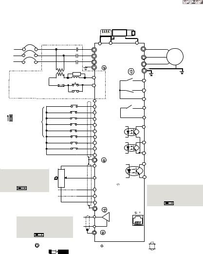
Figure 2 for models of VFD-VE Series (20HP/15kW and above) |
|
|
|
|||||||||
VFD150V23A/43A-2, VFD185V23A/43A-2, VFD220V23A/43A-2, VFD300V43A-2, VFD370V43A-2, |
||||||||||||
VFD450V43A-2, VFD300V23A-2, VFD370V23A-2, VFD550V43C-2, VFD750V43C-2 |
||||||||||||
|
|
|
|
|
|
|
|
DC choke |
brake unit |
|
|
|
|
|
|
|
|
|
|
|
(optional) |
(optional) |
brake resi stor |
|
|
|
|
|
|
|
|
|
|
|
VFDB |
|
||
|
|
|
|
|
|
|
|
|
(optional) |
|
||
|
|
|
|
|
|
|
|
|
|
|
||
|
|
Fus e/NFB(No Fuse B reaker) |
Jumper |
|
-(minus sign) |
|
||||||
|
|
|
+1 |
+2 |
Motor |
|||||||
R(L1) |
|
|
|
|
|
|
|
|
|
|||
|
|
|
|
|
|
|
R(L1) |
U(T1) |
|
IM |
||
S(L2) |
|
|
|
|
|
|
|
S(L2) |
V(T2) |
|
||
|
|
|
|
|
|
|
|
3~ |
||||
T(L3) |
|
|
|
|
|
|
|
T(L3) |
W(T3) |
|
||
|
|
|
|
|
|
|
|
|
||||
|
|
|
|
|
|
|
|
E |
|
E |
|
|
Recommended Circui t |
|
|
SA |
|
|
|
|
|||||
|
|
|
|
|
|
|
||||||
when power s upply |
|
|
|
RB |
|
RA |
|
|
||||
|
|
|
MC |
|
|
|
||||||
is turned OFF by a |
|
|
|
|
|
|
||||||
fault output. |
|
|
|
|
RC |
|
RB |
|
|
|||
If the fault occ urs, the |
|
OFF |
ON |
|
|
Multi-function c ontact output 1 |
||||||
contact will be O N to turn |
|
MC |
|
|
|
(relay) |
|
|||||
off the power and protec t the power s ystem. |
+24V |
|
RC |
factory setti ng: fault indication |
||||||||
Factory setting: |
|
FWD/STOP |
|
|
MRA |
|
|
|||||
|
|
FWD |
|
Multi-function c ontact output 2 |
||||||||
SINK Mode |
|
|
REV/STO P |
|
|
|
||||||
|
|
|
REV |
|
|
(r elay) |
|
|||||
Sink |
|
|
|
|
Multi-s tep 1 |
|
|
MRC |
48VDC 50mA |
|||
Sw1 |
|
|
|
|
MI1 |
|
||||||
|
Fac tor y |
|
|
|
|
|
|
factory setti ng: |
||||
Source |
|
|
Multi-step 2 |
|
MI2 |
MO1 |
|
indicates that it is running |
||||
|
setting |
|
|
|
||||||||
Please refer to |
|
Multi-s tep 3 |
|
|
Multi-function c ontact output 3 |
|||||||
Figure 3 for wiring |
|
|
MI3 |
|
|
(photocoupler) |
||||||
|
|
|
|
|
|
|||||||
of SINK mode and |
|
Multi-s tep 4 |
|
MI4 |
|
|
|
|
||||
SOURCEmode. |
|
|
No function |
|
MO2 |
|
Multi-function c ontact output 4 |
|||||
|
|
|
|
|
|
MI5 |
|
|||||
|
|
|
|
|
No function |
|
|
|
(photocoupler) |
|||
|
|
|
|
|
|
MI6 |
|
|
|
|
||
|
|
|
|
|
Digital Si gnal Common |
|
|
Multi-function |
||||
|
|
|
|
|
DCM |
|
|
|||||
|
|
* Don't apply the mains voltage direc tly |
|
MCM |
Photocoupler Output |
|||||||
|
|
E |
|
|
|
|||||||
|
|
to abov e terminals. |
|
|
|
DFM |
Digital Frequency Output |
|||||
|
|
|
|
|
|
|||||||
ACI current/v oltage selection |
|
|
+10V |
|
|
Terminal |
|
|||||
ACI Switch |
|
|
|
|
3 |
|
Power supply |
|
factory setti ng: 1:1 |
|||
|
|
|
|
|
+10V 20m A |
|
Duty =50%, 10V DC |
|||||
Make sure that power is OFF |
|
|
|
|||||||||
2 |
|
AVI |
|
|
Digital Si gnal Common |
|||||||
before changing the switch |
5K |
|
|
DCM |
||||||||
setting. |
|
|
|
|
|
1 |
|
Master Frequency |
DFM output s ignal s el ec ti on |
|||
0-20mA |
|
|
0-10V |
|
|
|
0 to 10V 47k |
|
DFM Switch |
|||
|
|
|
|
|
|
ACI |
|
|
||||
|
|
|
|
|
|
|
|
|
|
Make sure that power is OFF |
||
|
|
|
|
|
|
|
|
4~20mA/0~10V |
|
befor e c hanging the switch |
||
|
|
|
|
|
|
|
|
AUI |
|
|
||
|
|
|
|
|
|
|
|
-10~+ 10V |
|
setting. |
|
|
|
|
|
|
|
|
|
|
ACM |
|
|
OC |
TP |
|
|
|
|
|
|
|
|
Analog S ignal Common |
|
|
||
|
Analog Multifunc tion Output Terminal |
E |
|
|
|
|
||||||
|
AFM analog output selec tion |
|
AFM 0~ 10VDC/ 2mA |
RS-485 serial communication |
||||||||
|
AFM Switch |
|
|
|
|
ACM |
|
|
1: +E V |
|
||
|
Make sure that power is OFF |
|
|
|
2: G ND |
For c om munic ati on, |
||||||
|
befor e c hanging the switch |
|
Analog S ignal common |
3: SG - |
it needs to use |
|||||||
|
setting. |
|
|
|
|
E |
|
|
4: SG+ |
VFDUSB01/IFD8500 |
||
|
|
0-10V |
0-20mA |
|
|
|
5: NC |
to connect to PC. |
||||
|
|
|
|
|
|
|
|
|
|
|
6: NC |
|
|
|
|
Main c irc ui t (power) terminals |
Control c ircuit terminals |
Shielded l eads & Cable |
|||||||
|
|
|
|
|
|
NOTE |
The brake resis tor is built-i n to model V FD110V43B. |
|
||||
Revision August 2008, 03VE, SW V2.04 |
2-3 |
Chapter 2 Installation and Wiring|
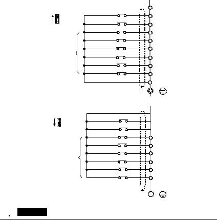
Figure 3 Wiring for SINK(NPN) mode and SOURCE(PNP) mode
SINK/NPN Mode
Sink |
FWD/STOP |
+24V |
|
FWD |
|||
SW1 |
REV/STOP |
||
|
|||
Source |
REV |
||
Multi-step1 |
|||
|
MI1 |
||
|
Multi-step2 |
||
|
MI2 |
||
|
Multi-step3 |
||
Factory |
MI3 |
||
Multi-step4 |
|||
setting |
MI4 |
||
|
No Function |
||
|
MI5 |
||
|
No Function |
||
|
MI6 |
||
|
Digital Signal Common |
||
|
DCM |
||
*Don't apply the mains voltage directly |
|||
E |
|||
to above terminals. |
|||
SOURCE/PNP Mode
Sink |
FWD/STOP |
|
SW1 |
||
REV/STOP |
||
Source |
||
Multi-step1 |
||
|
||
|
Multi-step2 |
|
Factory |
Multi-step3 |
|
Multi-step4 |
||
setting |
||
|
No Function |
|
|
No Function |
*Don't apply the mains voltage directly  to above terminals.
 +24V
+24V
 FWD
FWD
 REV
REV
MI1
MI2
MI3
MI4
MI5
MI6
 DCM
DCM
 E
E
 CAUTION!
1.The wiring of main circuit and control circuit should be separated to prevent erroneous actions.
2.Please use shield wire for the control wiring and not to expose the peeled-off net in front of the terminal.
3.Please use the shield wire or tube for the power wiring and ground the two ends of the shield wire or tube.
2.2 External Wiring
2-4 |
Revision August 2008, 03VE, SW V2.04 |
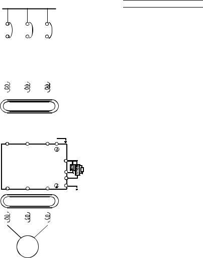
Power Supply
|
|
|
|
|
|
|
|
|
|
FUSE/NFB |
|
|
|
|||||
|
|
|
|
|
|
|
|
|
|
Magnetic |
|
|
|
|||||
|
|
|
|
|
|
|
|
|
|
|
|
|
||||||
|
|
|
|
|
|
|
|
|
|
contactor |
|
|
|
|||||
|
|
|
|
|
|
|
|
|
|
Input AC |
|
|
|
|||||
|
|
|
|
|
|
|
|
|
|
|
|
|
||||||
|
|
|
|
|
|
|
|
|
|
|
|
|
||||||
|
|
|
|
|
|
|
|
|
|
Line Reactor |
|
|
|
|||||
|
|
|
|
|
|
|
|
|
|
|
|
Zero-phase |
|
|||||
|
|
|
|
|
|
|
|
|
|
|
|
|
||||||
|
|
|
|
|
|
|
|
|
|
|
|
|
||||||
|
|
|
|
|
|
|
|
|
|
|
|
Reactor |
|
|
|
|||
|
|
|
|
|
|
|
|
|
|
|
|
|
|
|
|
|
|
|
|
|
|
|
EMI Filter |
|
|
|
|
|
|
|
|
|
|
|
|||
|
|
|
|
|
|
|
|
|
|
|
|
|
|
resBreakistor (optional) |
unitBreak(optional) |
istorresBreak |
(optional) |
|
|
|
|
|
|
|
|
|
|
|
|
|
|
|
|||||
|
R/L1 |
|
S/L2 |
T/L3 |
|
|
|
|
||||||||||
|
|
+/B1 |
|
|
|
|||||||||||||
|
|
|
|
|
|
|
|
|
|
|
|
|
||||||
|
|
|
|
|
|
|
|
|
|
|
|
B2 |
|
BR |
|
|||
|
|
|
|
|
|
|
|
|
|
|
|
|
|
|
||||
|
U/T1 |
|
V/T2 |
|
|
- |
|
|
|
|
|
|
||||||
|
|
W/T3 |
|
|
E |
|
|
|
|
|||||||||
|
|
|
|
|
|
|
|
|
|
|
|
|
|
|
||||
|
|
|
|
|
|
|
|
|
|
|
|
Zero-phase |
|
|||||
|
|
|
|
|
|
|
|
|
|
|
|
|
||||||
|
|
|
|
|
|
|
|
|
|
|
|
Reactor |
|
|
|
|||
|
|
|
|
|
|
|
|
|
|
Output AC |
|
|
|
|||||
|
|
|
|
|
|
|
|
|
|
|
|
|
||||||
|
|
|
|
|
|
|
|
|
|
|
|
|
||||||
|
|
|
|
|
|
|
|
|
|
Line Reactor |
|
|
|
|||||
|
|
|
|
|
|
|
|
|
|
|
|
|
|
|
|
|
|
|
|
|
|
|
|
|
|
|
|
|
|
|
|
|
|
|
|
|
|
|
|
|
|
|
|
|
|
|
|
|
|
|
|
|
|
|
|
|
|
|
|
|
|
Motor |
|
|
|
|
|
|
|
|
|
|
|
||
Chapter 2 Installation and Wiring| 
Items |
Explanations |
|
Power |
Please follow the specific power |
|
supply requirements shown in |
||
supply |
||
Appendix A. |
||
|
||
|
There may be an inrush current |
|
Fuse/NFB |
during power up. Please check the |
|
chart of Appendix B and select the |
||
(Optional) |
||
correct fuse with rated current. Use of |
||
|
||
|
an NFB is optional. |
|
Magnetic |
Please do not use a Magnetic |
|
contactor as the I/O switch of the AC |
||
contactor |
||
motor drive, as it will reduce the |
||
(Optional) |
||
operating life cycle of the AC drive. |
||
|
||
|
|
|
|
Used to improve the input power |
|
|
factor, to reduce harmonics and |
|
|
provide protection from AC line |
|
|
disturbances (surges, switching |
|
Input AC |
spikes, short interruptions, etc.). AC |
|
Line Reactor |
line reactor should be installed when |
|
(Optional) |
the power supply capacity is 500kVA |
|
|
or more or advanced capacity is |
|
|
activated .The wiring distance should |
|
|
be ≤ 10m. Refer to appendix B for |
|
|
details. |
|
|
Zero phase reactors are used to |
|
Zero-phase |
reduce radio noise especially when |
|
audio equipment is installed near the |
||
Reactor |
||
inverter. Effective for noise reduction |
||
(Ferrite Core |
||
on both the input and output sides. |
||
Common |
Attenuation quality is good for a wide |
|
Choke) |
||
range from AM band to 10MHz. |
||
(Optional) |
||
Appendix B specifies the zero phase |
||
|
||
|
reactor. (RF220X00A) |
|
EMI filter |
To reduce electromagnetic |
|
interference, please refer to Appendix |
||
(Optional) |
||
B for more details. |
||
|
||
|
|
|
Brake |
Used to reduce the deceleration time |
|
of the motor. Please refer to the chart |
||
Resistor |
||
in Appendix B for specific Brake |
||
(Optional) |
||
Resistors. |
||
|
||
|
|
|
Output AC |
Motor surge voltage amplitude |
|
depends on motor cable length. For |
||
Line Reactor |
||
applications with long motor cable |
||
(Optional) |
(>20m), it is necessary to install a |
|
|
||
|
|
2.3Main Circuit
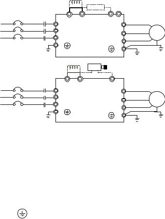
2.3.1 Main Circuit Connection
Revision August 2008, 03VE, SW V2.04 |
2-5 |
Chapter 2 Installation and Wiring|
Figure 1 for the main terminals
|
|
|
Brak e res istor(O pti onal) |
||
No-fuse break er |
|
|
|
|
|
(NFB) |
MC |
+1 |
+2/B1 |
B2 - |
|
R |
|
R(L1 ) |
|
U (T 1) |
|
S |
|
S(L2 ) |
|
V(T2) |
|
T |
|
T(L 3) |
|
||
|
|
W(T3) |
|||
|
|
E |
|
||
|
|
|
E |
||
|
|
|
|
||
Figure 2 for the main terminals |
|
|
|
||
|
|
|
VFDB |
Brak e res istor |
|
|
|
|
|
(optional) |
|
No-fuse break er |
|
|
|
- |
|
(NFB) |
MC |
+1 |
+2 |
||
|
|||||
R |
|
R(L1 ) |
|
U (T 1) |
|
S |
|
S(L2 ) |
|
V(T2) |
|
T |
|
T(L 3) |
|
||
|
|
W(T3) |
|||
|
|
E |
|
||
|
|
|
E |
||
|
|
|
|
||
Motor
IM 3~
Motor
IM 3~
|
Terminal Symbol |
Explanation of Terminal Function |
|
|
R/L1, S/L2, T/L3 |
AC line input terminals (1-phase/3-phase) |
|
|
|
|
|
|
U/T1, V/T2, W/T3 |
AC drive output terminals for connecting 3-phase |
|
|
induction motor |
|
|
|
|
|
|
+1, +2 |
Connections for DC Choke (optional) |
||
|
|
|
|
|
+2/B1, B2 |
Connections for Brake Resistor (optional) |
|
|
+2~(-), +2/B1~(-) |
Connections for External Brake Unit (VFDB series) |
|
|
|
|
|
|
|
Earth connection, please comply with local regulations. |
|
|
|
|
|
2-6 |
Revision August 2008, 03VE, SW V2.04 |
Chapter 2 Installation and Wiring| 
Mains power terminals (R/L1, S/L2, T/L3)
Connect these terminals (R/L1, S/L2, T/L3) via a no-fuse breaker or earth leakage breaker to 3-phase AC power (some models to 1-phase AC power) for circuit protection. It is unnecessary to consider phase-sequence.
It is recommended to add a magnetic contactor (MC) in the power input wiring to cut off power quickly and reduce malfunction when activating the protection function of AC motor drives. Both ends of the MC should have an R-C surge absorber.
Please make sure to fasten the screw of the main circuit terminals to prevent sparks which is made by the loose screws due to vibration.
Please use voltage and current within the regulation shown in Appendix A.
When using leakage-current breaker to prevent leakage current,
Do NOT run/stop AC motor drives by turning the power ON/OFF. Run/stop AC motor drives by RUN/STOP command via control terminals or keypad. If you still need to run/stop AC drives by turning power ON/OFF, it is recommended to do so only ONCE per hour.
Do NOT connect 3-phase models to a 1-phase power source.
Output terminals for main circuit (U, V, W)
When the AC drive output terminals U/T1, V/T2, and W/T3 are connected to the motor terminals U/T1, V/T2, and W/T3, respectively, the motor will rotate counterclockwise (as viewed on the shaft end of the motor) when a forward operation command is received. To permanently reverse the direction of motor rotation, switch over any of the two motor leads.
Forward running
DO NOT connect phase-compensation capacitors or surge absorbers at the output terminals of AC motor drives.
With long motor cables, high capacitive switching current peaks can cause over-current, high leakage current or lower current readout accuracy. To prevent this, the motor cable should be less than 20m for 3.7kW models and below. And the cable should be less than 50m for 5.5kW models and above. For longer motor cables use an AC output reactor.
Use well-insulated motor, suitable for inverter operation.
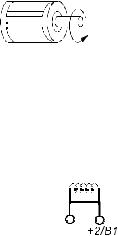
Terminals [+1, +2] for connecting DC reactor
DC reactor
Jumper
+1
Revision August 2008, 03VE, SW V2.04 |
2-7 |
Loading...