


VFD-L Series User Manual
115V 200W-400W
230V 200W-2HP
Simple General Purpose AC Drive
ASIA |
NORTH/SOUTH AMERICA |
EUROPE |
DELTA ELECTRONICS, INC. |
DELTA PRODUCTS |
DELTRONICS (Netherlands) |
TAOYUAN Plant/ |
CORPORATION |
B.V. |
31-1, SHIEN PAN ROAD, |
Sales Office/ |
Sales Office/ |
KUEI SAN INDUSTRIAL ZONE |
P.O. BOX 12173 |
Industriegebied Venlo Nr. 9031 |
TAOYUAN 333, TAIWAN, R.O.C 5101 DAVIS DRIVE |
Columbusweg 20 |
|
TEL: 886-3-362-6301 |
RTP, NC 27709 U. S. A. |
NL-5928 LC Venlo |
FAX: 886-3-362-7267 |
TEL: 1-919-767-3813 |
The Netherlands |
http://www.deltaww.com/acdrives FAX: 1-919-767-3969 |
TEL: 31-77-342-1930 |
|
|
http://www.deltaww.com/acdrives FAX: 31-77-342-1931 |
|
Preface
Thank you for choosing DELTA’s VFD-L series AC Drive. The VFD-L series is manufactured using high-quality components, material and incorporating the latest microprocessor technology available.
This manual will help in the installation, parameter setting, troubleshooting, and daily maintenance of the AC motor drive. To guarantee safe operation of the equipment, read the following safety guidelines before connecting power to the AC motor drive. Keep this operating manual handy and distribute to all users for reference.
Important Notes:
TDANGER! AC input power must be disconnected before any maintenance. Do not connect or
disconnect wires while power is applied to the circuit. Only qualified technicians should perform maintenance on the VFD-L.
TCAUTION! There are highly sensitive MOS components on the printed circuit boards. These
components are especially sensitive to static electricity. To avoid damaging these components, do not touch the circuit boards with metal objects or your bare hands.
TDANGER! A charge may still remain in the DC-link capacitor with hazardous voltages even
after the power has been turned off. To avoid personal injury, do not remove the cover of the AC drive until all “DISPLAY LED” lights on the digital keypad are off. Please note that there are live components exposed when the AC drive is open,. Be careful to not touch these live parts.
TCAUTION! Ground the VFD-L using the ground terminal.  The grounding method must
comply with the laws of the country where the AC drive is to be installed.
TDANGER! The AC drive may be destroyed beyond repair if power is misapplied to the
input/output terminals. Never connect the AC drive output terminals U/T1, V/T2, W/T3 directly to the AC main circuit power supply.
1
Chapter 1 Receiving and Inspection
This VFD-L AC drive has gone through rigorous quality control tests at the factory before shipment. Since many things may happen during shipping, please check for the following after receiving the
AC motor drive.
èInspect the unit to insure it was not damaged during shipment.
èMake sure that the part number indicated on the nameplate corresponds with the part number of your order.
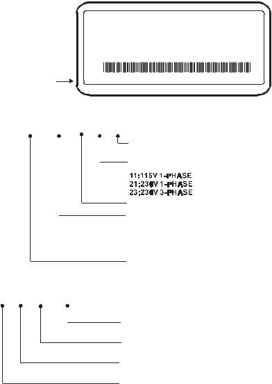
Nameplate Information: Example of 1HP230V
A C D riv e M o d e l 
In p u t S p e c . 
O u tp u t S p e c .
O u tp u t F re q . R a n g e 
B a r C o d e
S e ria l N O .
Model Explanation:
M O D E :V F D 0 0 7 L 2 1 A
IN P U T :1 P H /9 .7 A 3 P H /5 .1 A 2 0 0 - 2 4 0 V 5 0 - 6 0 H z O U T P U T :3 P H 0 - 2 4 0 V 4 . 2 A 1 .6 k VA 1 H P
F re q . R a n g e:1 .0 ~ 4 0 0 H z
0 0 7 L 2 1 AT 1 0 1 0 0 1
D E LTA E L E C T R O N IC S , IN C . M A D E IN X X X X X
V F D 0 0 7 L 2 1 A
v e rs io n
A sta n d a rd
B in c lu d in g E M I F ilte r
In p u t v o lta g e
V F D -L s e rie s
A p p lic a b le m o to r ca p a c ity
0 0 2 :0 .2 k W
0 0 4 :0 .4 k W
0 0 7 :0 .7 5 k W
0 1 5 :1 .5 k W
Va ria b le F re q u e n c y D rive
Series Number Explanation:
T |
3 |
1 0 |
0 0 1 |
P ro d u c tio n n u m b e r
P ro d u c tio n w e e k
P ro d u c tio n y ea r 2 0 0 3
P ro d u c tio n fa cto ry
(T: Ta o y u a n , W : W u ju a n g )
If there is any nameplate information not corresponding to your purchase order or any problem, please contact your distributor.
2

Dimension
RUN |
STOP |
FWD |
|
REV |
|
|
MODE |
|
RESET |
RUN |
PROG |
STOP |
DATA |
VFD-L
MIN. MAX. 0.75KW
230V IPHASE
WARNING
Do not connect AC power to output
8 |
terminals (U,V,W). |
|
Do not inspect components until LEDs |
||
|
||
+ |
are turned off for at least 1min. |
|
Read the user manual before operation. |
||
|
RA RC + 10VAVI M0 M1 M2 M3 GND RS-485
3
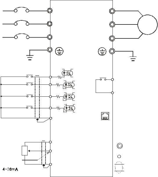
Chapter 2 Wiring
Basic Wiring Diagram
Users must connect wiring according to the circuit diagram shown below. Please follow all National and State wiring codes, when wiring the VFD-L.
M a in C ir c u it P o w e r |
|
|
|
|
|
|
|
|
|
|
|
5 / |
|
|
5 / |
8 7 |
|
6 / |
|
|
6 / |
9 7 |
,0 |
|
|
a |
|||
|
|
|
|
|
|
7 / |
|
|
7 / |
: 7 |
M o to r |
|
|
|
|
||
F a c to ry d e fa u lt s e ttin g s |
+ 1 8 V |
|
|
||
|
|
|
|||
F o rw a rd /S to p |
M 0 |
4 .7 Kè |
R A |
|
|
|
|
|
+ 1 8 V |
M u lti-fu n c tio n in d ic a tio n |
|
|
|
|
|
||
R e v e rs e /S to p |
M 1 |
4 .7 Kè |
|
o u tp u t c o n ta c ts |
|
|
|
||||
|
|
|
+ 1 8 V |
R C 1 2 0 VA C /2 8 V D C 3 A |
|
R e s e t |
|
M 2 |
4 .7 Kè |
|
F a c to ry d e fa u lt: |
|
|
|
|
|
F a u lt In d ic a tio n |
|
|
|
+ 1 8 V |
|
|
M u lti-s te p 1 |
|
M 3 |
4 .7 Kè |
|
|
|
|
|
|
R J -11 |
1 :+ E V |
C o m m o n S ig n a l |
G N D |
|
|
||
|
|
2 :G N D |
|||
|
|
|
|
6'1 |
3 :S G - |
|
|
|
|
R S - 4 8 5 |
4 :S G + |
P o w e r s u p p ly fo r P o te n tio m e te r |
|
C o m m u n ic a tio n |
|
||
|
p o r t |
|
|||
+ 1 0 V 1 0 m A ( M A X ) |
|
|
|
||
|
+ 1 0 V |
|
|
||
M a s te r F re q . s e ttin g |
3 |
|
|
M a in c ir c u it (p o w e r ) |
|
|
|
|
|||
|
2 |
|
|
|
|
|
|
AV I |
|
te rm in a ls |
|
A n a lo g v o lta g e V R |
|
|
|||
0 1 0 V D C |
1 |
|
|
|
C o n tro l c irc u it te rm in a ls |
V R š3 K 5 K è |
|
|
|
|
|
A n a lo g c u rr e n t |
|
|
G N D |
|
S h ie ld e d le a d s |
|
|
|
|
|
|
N O T E : D o n o t p lu g in a M o d e m o r te le p h o n e lin e to th e R S - 4 8 5 c o m m u n ic a tio n p o rt, |
|||||
p e rm a n e n t d a m a g e m a y re s u lt. Te rm in a ls 1 & 2 a r e th e p o w e r s o u rc e fo r th e |
|||||
o p tio n a l c o p y k e y p a d a n d s h o u ld n o t b e u s e d w h ile u s in g R S - 4 8 5 |
|||||
c o m m u n ic a tio n . |
|
|
|
||
* If th e A C D r iv e m o d e l is V F D 0 0 2 L 11 A /B , V F D 0 0 4 L 11 A /B , V F D 0 0 2 L 2 1 B , V F D 0 0 4 L 2 1 B |
|||||
o r V F D 0 0 7 L 2 1 B , p le a s e u s e p o w e r te rm in a ls R /L 1 a n d S /L 2 . |
|||||
* If th e A C D riv e m o d e l is V F D 0 0 2 L 2 1 A , V F D 0 0 4 L 2 1 A o r V F D 0 0 7 L 2 1 A , 3 p h a s e p o w e r |
|||||
m a y b e u s e d o n R /L 1 , S /L 2 , T /L 3 . |
|
|
|||
* If th e A C D riv e m o d e l is V F D 0 1 5 L 2 3 A , s in g le p h a s e p o w e r is n o t a llo w e d . |
|||||
|
|
|
|
4 |
|
 Loading...