


9" Bench Band Saw
(Model SM400)
PART NO. 638518-00 11-05
Copyright © 2005 Delta Machinery
To learn more about DELTA MACHINERY |
|
|
ESPAÑOL: PÁGINA 25 |
||
visit our website at: www.deltamachinery.com. |
||
|
||
For Parts, Service, Warranty or other Assistance, |
FRANÇAIS: PAGE 48 |
please call 1-800-223-7278 (In Canada call 1-800-463-3582).
MANUAL INSTRUCTION

SAFETY GUIDELINES - DEFINITIONS
This manual contains information that is important for you to know and understand. This information relates to protecting YOUR SAFETY and PREVENTING EQUIPMENT PROBLEMS. To help you recognize this information, we use the symbols to the right. Please read the manual and pay attention to these sections.
 Indicates an imminently hazardous situation which, if not avoided, will result in death or serious injury.
Indicates a potentially hazardous situation which, if not avoided, could result in death or serious injury.
Indicates a potentially hazardous situation which, if not avoided, may result in minor or moderate injury.
Used without the safety alert symbol indicates potentially hazardous situation which, if not avoided, may result in property damage.
Some dust created by power sanding, sawing, grinding, drilling, and other construction activities contains chemicals known to cause cancer, birth defects or other reproductive harm. Some examples of these chemicals are:
•lead from lead-based paints,
•crystalline silica from bricks and cement and other masonry products, and
•arsenic and chromium from chemically-treated lumber (CCA).
Your risk from these exposures varies, depending on how often you do this type of work. To reduce your exposure to these chemicals: work in a well ventilated area, and work with approved safety equipment, such as those dust masks that are specially designed to filter out microscopic particles.
•Avoid prolonged contact with dust from power sanding, sawing, grinding, drilling, and other construction activities. Wear protective clothing and wash exposed areas with soap and water. Allowing dust to get into your mouth, eyes, or lay on the skin may promote absorption of harmful chemicals.
Use of this tool can generate and/or disperse dust, which may cause serious and permanent respiratory or other injury. Always use NIOSH/OSHA approved respiratory protection appropriate for the dust exposure. Direct particles away from face and body.
Wear appropriate hearing protection during use. Under some conditions and duration of use, noise from this product may contribute to hearing loss.
GENERAL SAFETY RULES
 READ AND UNDERSTAND ALL WARNINGS AND OPERATING INSTRUCTIONS BEFORE USING THIS EQUIPMENT. Failure to follow all instructions listed below, may result in electric shock, fire, and/or serious personal injury or property damage.
IMPORTANT SAFETY INSTRUCTIONS
Woodworking can be dangerous if safe and proper operating procedures are not followed. As with all machinery, there are certain hazards involved with the operation of the product. Using the machine with respect and caution will considerably lessen the possibility of personal injury. However, if normal safety precautions are overlooked or ignored, personal injury to the operator may result. Safety equipment such as guards, push sticks, hold-downs, featherboards, goggles, dust masks and hearing protection can reduce your potential for injury. But even the best guard won’t make up for poor judgment, carelessness or inattention. Always use common sense and exercise caution in the workshop. If a procedure feels dangerous, don’t try it. Figure out an alternative procedure that feels safer. REMEMBER: Your personal safety is your responsibility. For additional information please visit our website www.deltamachinery.com.
 This machine was designed for certain applications only. Delta Machinery strongly recommends that this machine not be modified and/or used for any application other than that for which it was designed. If you have any questions relative to a particular application, DO NOT use the machine until you have first contacted Delta to determine if it can or should be performed on the product.
Technical Service Manager
Delta Machinery
4825 Highway 45 North
Jackson, TN 38305
(IN CANADA: 505 SOUTHGATE DRIVE, GUELPH, ONTARIO
N1H 6M7)
2

GENERAL SAFETY RULES
 Read and understand all instructions. Failure to follow all instructions listed below may result in electric shock, fire and/or serious injury.
1.FOR YOUR OWN SAFETY, READ THE INSTRUCTION MANUAL BEFORE OPERATING THE MACHINE. Learning the machine’s application, limitations, and specific hazards will greatly minimize the possibility of accidents and injury.
2.USE CERTIFIED SAFETY EQUIPMENT. Eye protection equipment should comply with ANSI Z87.1 standards, hearing equipment should comply with ANSI S3.19 standards, and dust mask protection should comply with MSHA/NIOSH certified respirator standards. Splinters, air-borne debris, and dust can cause irritation, injury, and/or illness.
3.DRESS PROPERLY. Do not wear tie, gloves, or loose clothing. Remove watch, rings, and other jewelry. Roll up your sleeves. Clothing or jewelry caught in moving parts can cause injury.
4.DO NOT USE THE MACHINE IN A DANGEROUS ENVIRONMENT. The use of power tools in damp or wet locations or in rain can cause shock or electrocution. Keep your work area well-lit to prevent tripping or placing arms, hands, and fingers in danger.
5.MAINTAIN ALL TOOLS AND MACHINES IN PEAK CONDITION. Keep tools sharp and clean for best and safest performance. Follow instructions for lubricating and changing accessories. Poorly maintained tools and machines can further damage the tool or machine and/or cause injury.
6.CHECK FOR DAMAGED PARTS. Before using the machine, check for any damaged parts. Check for alignment of moving parts, binding of moving parts, breakage of parts, and any other conditions that may affect its operation. A guard or any other part that is damaged should be properly repaired or replaced. Damaged parts can cause further damage to the machine and/or injury.
7.KEEP THE WORK AREA CLEAN. Cluttered areas and benches invite accidents.
8.KEEP CHILDREN AND VISITORS AWAY. Your shop is a potentially dangerous environment. Children and visitors can be injured.
9.REDUCE THE RISK OF UNINTENTIONALSTARTING.
Make sure that the switch is in the “OFF” position before plugging in the power cord. In the event of a power failure, move the switch to the “OFF” position. An accidental start-up can cause injury.
10.USE THE GUARDS. Check to see that all guards are in place, secured, and working correctly to prevent injury.
11.REMOVE ADJUSTING KEYS AND WRENCHES BEFORE STARTING THE MACHINE. Tools, scrap pieces, and other debris can be thrown at high speed, causing injury.
12.USE THE RIGHT MACHINE. Don’t force a machine or an attachment to do a job for which it was not designed. Damage to the machine and/or injury may result.
13.USE RECOMMENDED ACCESSORIES. The use of accessories and attachments not recom-
mended by Delta may cause damage to the machine or injury to the user.
14.USE THE PROPER EXTENSION CORD. Make sure your extension cord is in good condition. When using an extension cord, be sure to use one heavy enough to carry the current your product will draw. An undersized cord will cause a drop in line voltage, resulting in loss of power and overheating. See the Extension Cord Chart for the correct size depending on the cord length and nameplate ampere rating. If in doubt, use the next heavier gauge. The smaller the gauge number, the heavier the cord.
15.SECURE THE WORKPIECE. Use clamps or a vise to hold the workpiece when practical. Loss of control of a workpiece can cause injury.
16.FEED THE WORKPIECE AGAINST THE DIRECTION OF THE ROTATION OF THE BLADE, CUTTER, OR ABRASIVE SURFACE. Feeding it from the other direction will cause the workpiece to be thrown out at high speed.
17.DON’T FORCE THE WORKPIECE ON THE MACHINE. Damage to the machine and/or injury may result.
18.DON’T OVERREACH. Loss of balance can make you fall into a working machine, causing injury.
19.NEVER STAND ON THE MACHINE. Injury could occur if the tool tips, or if you accidentally contact the cutting tool.
20.NEVER LEAVE THE MACHINE RUNNING UNATTENDED. TURN THE POWER OFF. Don’t leave the machine until it comes to a complete stop.Achild or visitor could be injured.
21.TURN THE MACHINE “OFF”,AND DISCONNECT THE MACHINE FROM THE POWER SOURCE before installing or removing accessories, before adjusting or changing set-ups, or when making repairs. An accidental start-up can cause injury.
22.MAKE YOUR WORKSHOP CHILDPROOF WITH PADLOCKS, MASTER SWITCHES, OR BY REMOVING STARTER KEYS. The accidental start-up of a machine by a child or visitor could cause injury.
23. STAY ALERT, WATCH WHAT YOU ARE DOING,
AND USE COMMON SENSE. DO NOT USE THE MACHINE WHEN YOU ARE TIRED OR UNDER THE INFLUENCE OF DRUGS, ALCOHOL, OR MEDICATION. A moment of inattention while operating power tools may result in injury.
24.THE DUST GENERATED by certain woods and wood products can be injurious to your health. Always operate machinery in well-ventilated areas, and provide for proper dust removal. Use wood dust collection systems whenever possible.
3

ADDITIONAL SAFETY RULES FOR
BAND SAWS
Read and understand all instructions. Failure to follow all instructions listed below may result in electric shock, fire and/or serious injury.
1.DO NOT OPERATE THIS MACHINE UNTIL it is assembled and installed according to the instructions.
2.OBTAIN ADVICE from your supervisor, instructor, or another qualified person if you are not familiar with the operation of this tool.
3.FOLLOW ALL WIRING CODES and recommended electrical connections.
4.ALWAYS USE BLADE GUARD. Check to see that they are in place, properly adjusted, secured, and working correctly.
5.USE PROPER BLADE SIZE and type.
6.ADJUST THE UPPER BLADE GUIDE so that it is about 1/8" above the workpiece.
7.PROPERLY ADJUST the blade tension, tracking, blade guides, and blade support bearings.
8.KEEP ARMS, HANDS, AND FINGERS away from the blade.
9.AVOID AWKWARD OPERATIONS and hand positions where a sudden slip could cause a hand to move into the blade.
10.NEVER START THE MACHINE before clearing the table of all objects (tools, scrap pieces, etc.).
11.NEVER START THE MACHINE with the workpiece against the blade.
12.HOLD WORKPIECE FIRMLY against the table. DO NOT attempt to saw a workpiece that does not have a flat surface against the table.
13.HOLD WORKPIECE FIRMLY and feed into blade at a moderate speed.
14.NEVER REACH UNDER THE TABLE while the machine is running.
15.TURN THE MACHINE “OFF” to back out of an uncompleted or jammed cut.
16.MAKE “RELIEF” CUTS prior to cutting long curves.
17.TURN THE MACHINE “OFF” and wait for the blade to stop prior to cleaning the blade area, removing debris near the blade, removing or securing workpiece, or changing the angle of the table. A coasting blade can be dangerous.
18.NEVER PERFORM LAYOUT, ASSEMBLY, or set-up work on the table/work area when the machine is running.
19. TURN THE MACHINE “OFF” AND DISCONNECT THE MACHINE from the power source before installing or removing accessories, before adjusting or changing set-ups, or when making repairs.
20.TURN THE MACHINE “OFF”, disconnect the machine from the power source, and clean the table/work area before leaving the machine. LOCK THE SWITCH IN THE “OFF” POSITION to prevent unauthorized use.
21. THIS BAND SAW IS INTENDED FOR INDOOR USE ONLY.
22.YOUR BAND SAW MUST be securely fastened to a stand or workbench. If there is any tendency for the stand or workbench to move during operation, the stand or workbench MUST be fastened to the floor.
23.MAKE SURE blade is properly tensioned before operating saw.
24.MAKE SURE the blade teeth point downward toward the table.
25.DO NOT cut material that is too small to be safely supported.
26.NEVER attempt to cut a curve that is too tight for the blade being used.
27.THE USE of attachments and accessories not recommended by Delta may result in the risk of injuries.
28.SHOULD any part of your Band Saw be missing, damaged or fail in any way, or any electrical component fail to perform properly, shut off switch and remove plug from power supply outlet. Replace missing, damaged or failed parts before resuming operation.
29.ADDITIONAL INFORMATION regarding the safe and proper operation of power tools (i.e. a safety video) is available from the Power Tool Institute, 1300 Sumner Avenue, Cleveland, OH 44115-2851 (www.powertoolinstitute.com). Information is also available from the National Safety Council, 1121 Spring Lake Drive, Itasca, IL 60143-3201. Please refer to the American National Standards Institute ANSI 01.1 Safety Requirements for Woodworking Machines and the U.S. Department of Labor OSHA 1910.213 Regulations.
SAVE THESE INSTRUCTIONS.
Refer to them often
and use them to instruct others.
4
POWER CONNECTIONS
A separate electrical circuit should be used for your machines. This circuit should not be less than #12 wire and should be protected with a 20 Amp time lag fuse. If an extension cord is used, use only 3-wire extension cords which have 3- prong grounding type plugs and matching receptacle which will accept the machine’s plug. Before connecting the machine to the power line, make sure the switch is in the “OFF” position and be sure that the electric current is of the same characteristics as indicated on the machine. All line connections should make good contact. Running on low voltage will damage the machine.
 SHOCK HAZARD: DO NOT EXPOSE THE MACHINE TO RAIN OR OPERATE THE MACHINE IN DAMP LOCATIONS.
GROUNDING INSTRUCTIONS
 SHOCK HAZARD:THIS MACHINE MUST BE GROUNDED WHILE IN USE TO PROTECT THE OPERATOR FROM ELECTRIC SHOCK.
Your machine is wired for 120 volt, 60 HZ alternating current. Before connecting the machine to the power source, make sure the switch is in the “OFF” position.
1. All grounded, cord-connected machines:
In the event of a malfunction or breakdown, grounding provides a path of least resistance for electric current to reduce the risk of electric shock. This machine is equipped with an electric cord having an equipment-grounding conductor and a grounding plug. The plug must be plugged into a matching outlet that is properly installed and grounded in accordance with all local codes and ordinances.
Do not modify the plug provided - if it will not fit the outlet, have the proper outlet installed by a qualified electrician.
Improper connection of the equipment-grounding conductor can result in risk of electric shock. The conductor with insulation having an outer surface that is green with or without yellow stripes is the equipmentgrounding conductor. If repair or replacement of the electric cord or plug is necessary, do not connect the equipment-grounding conductor to a live terminal.
Check with a qualified electrician or service personnel if the grounding instructions are not completely understood, or if in doubt as to whether the machine is properly grounded.
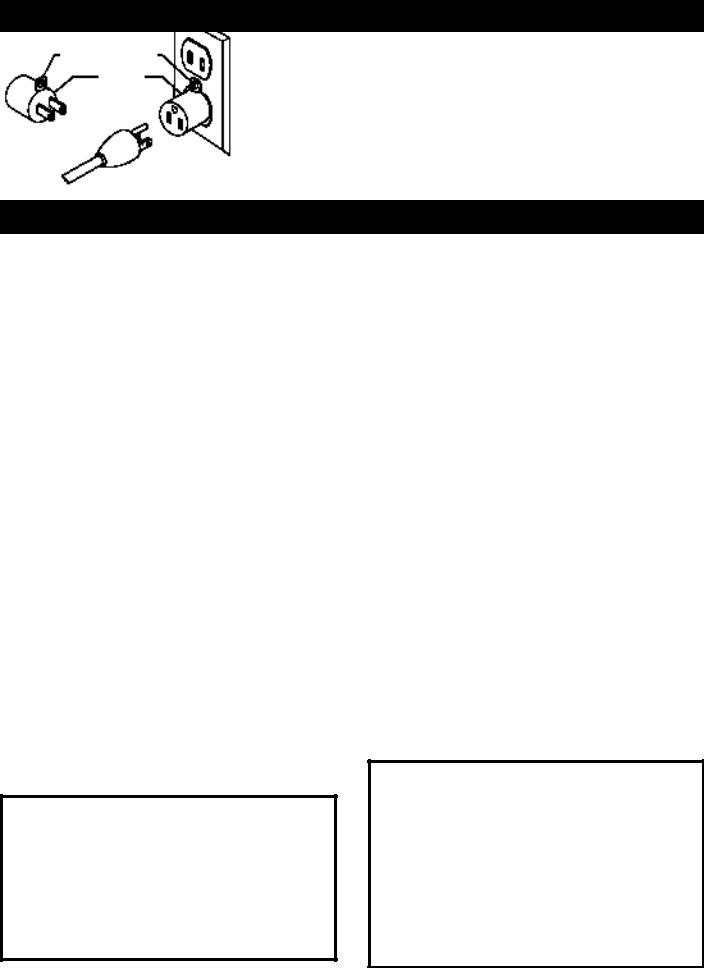
Use only 3-wire extension cords that have 3-prong grounding type plugs and matching 3-conductor receptacles that accept the machine’s plug, as shown in Fig. A.
Repair or replace damaged or worn cord immediately.
GROUNDED OUTLET BOX
CURRENT
CARRYING
PRONGS
2. Grounded, cord-connected machines intended for use on a supply circuit having a nominal rating less than 150 volts:
If the machine is intended for use on a circuit that has an outlet that looks like the one illustrated in Fig. A, the machine will have a grounding plug that looks like the plug illustrated in Fig. A. A temporary adapter, which looks like the adapter illustrated in Fig. B, may be used to connect this plug to a matching 2-conductor receptacle as shown in Fig. B if a properly grounded outlet is not available. The temporary adapter should be used only until a properly grounded outlet can be installed by a qualified electrician. The green-colored rigid ear, lug, and the like, extending from the adapter must be connected to a permanent ground such as a properly grounded outlet box. Whenever the adapter is used, it must be held in place with a metal screw.
NOTE: In Canada, the use of a temporary adapter is not permitted by the Canadian Electric Code.
 SHOCK HAZARD: IN ALL CASES, MAKE CERTAIN THE RECEPTACLE IN QUESTION IS PROPERLY GROUNDED. IF YOU ARE NOT SURE HAVE A QUALIFIED ELECTRICIAN CHECK THE RECEPTACLE.
GROUNDED OUTLET BOX
GROUNDING
MEANS
ADAPTER
GROUNDING BLADE
IS LONGEST OF THE 3 BLADES
Fig. A |
5 |
Fig. B |
|

EXTENSION CORDS
 Use proper extension cords. Make sure your extension cord is in good condition and is a 3-wire extension cord which has a 3-prong grounding type plug and matching receptacle which will accept the machine’s plug. When using an extension cord, be sure to use one heavy enough to carry the current of the machine. An undersized cord will cause a drop in line voltage, resulting in loss of power and overheating. Fig. C, shows the correct gauge to use depending on the cord length. If in doubt, use the next heavier gauge. The smaller the gauge number, the heavier the
cord.
MINIMUM GAUGE EXTENSION CORD
RECOMMENDED SIZES FOR USE WITH STATIONARY ELECTRIC MACHINES
Ampere |
|
Total Length |
Gauge of |
Rating |
Volts |
of Cord in Feet |
Extension Cord |
|
|
|
|
0-6 |
120 |
up to 25 |
18 AWG |
0-6 |
120 |
25-50 |
16 AWG |
0-6 |
120 |
50-100 |
16 AWG |
0-6 |
120 |
100-150 |
14 AWG |
6-10 |
120 |
up to 25 |
18 AWG |
6-10 |
120 |
25-50 |
16 AWG |
6-10 |
120 |
50-100 |
14 AWG |
6-10 |
120 |
100-150 |
12 AWG |
|
|
|
|
10-12 |
120 |
up to 25 |
16 AWG |
10-12 |
120 |
25-50 |
16 AWG |
10-12 |
120 |
50-100 |
14 AWG |
10-12 |
120 |
100-150 |
12 AWG |
12-16 |
120 |
up to 25 |
14 AWG |
12-16 |
120 |
25-50 |
12 AWG |
12-16 |
120 |
GREATER THAN 50 FEET NOT RECOMMENDED |
|
|
|
|
|
Fig. C
OPERATING INSTRUCTIONS
FOREWORD
The ShopMaster Model SM400 is built for precision and performance. The SM400 comes with a powerful 3 amp motor, rack and pinion upper blade guide assembly, table tilting assembly, and a flexible lamp.
UNPACKING AND CLEANING
Carefully unpack the machine and all loose items from the shipping container. Remove the protective coating from all unpainted surfaces. This coating may be removed with a soft cloth moistened with kerosene (do not use acetone, gasoline or lacquer thinner for this purpose). After cleaning, cover the unpainted surfaces with a good quality household floor paste wax.
NOTICE: THE MANUAL COVER PHOTO ILLUSTRATES THE CURRENT PRODUCTION MODEL. ALL OTHER ILLUSTRATIONS ARE REPRESENTATIVE ONLY AND MAY NOT DEPICT THE ACTUAL COLOR, LABELING OR ACCESSORIES AND MAY BE INTENDED TO ILLUSTRATE TECHNIQUE ONLY.
ASSEMBLY TOOLS REQUIRED
1.) 3mm hex wrench - supplied |
3.) flat-head screwdriver |
2.) 4mm hex wrench - supplied |
4.) phillips screwdriver |
ASSEMBLY TIME ESTIMATE
1 hour or less
6
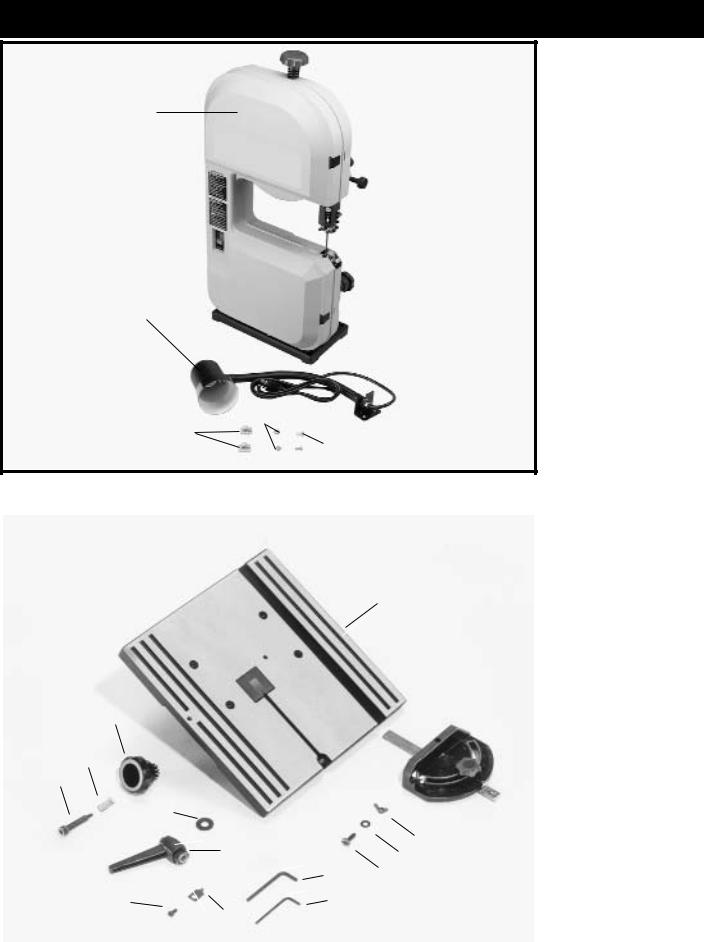
9" BENCH BAND SAW PARTS
1
1 - Band Saw
2 - Lamp
3 - Lamp Cord Clamps(2)
4 - 1/4" Lockwashers (2)
5 - M6x1x12mm Cap
Head Screws (2)
2
4
3
 5
5
Fig. 2
|
|
|
|
|
6 |
- Table |
|
|
|
|
|
7 |
- M6x1 Wing Nut |
|
|
|
|
|
8 |
- M6 Flat Washer |
|
|
|
6 |
|
9 |
- M6x1x30mm Pan |
|
|
|
|
|
||
|
|
|
|
|
|
Head Screw |
|
|
|
|
|
10 |
- 4mm Hex Wrench |
|
|
|
19 |
11 |
- 3mm Hex Wrench |
|
|
|
|
|
|
12 |
- Pointer |
|
|
|
|
|
||
16 |
|
|
|
|
13 |
- M5x.8x10mm Pan |
|
|
|
|
|
|
Head Screw |
17 |
|
|
|
|
14 |
- M10 Flat Washer |
18 |
|
|
|
|
15 |
- Lever Assembly |
|
14 |
|
|
|
16 |
- Pinion Knob |
|
|
|
7 |
|
17 |
- Spring |
|
15 |
|
|
18 |
- Special Screw |
|
|
|
8 |
|
|||
|
|
10 |
|
|
|
|
|
|
9 |
|
19 |
- Miter Guage |
|
|
|
|
|
|||
13 |
|
11 |
|
|
|
(Optional) |
12 |
|
|
|
|
||
|
|
|
|
|
|
|
|
|
|
|
|
|
|
|
|
Fig. 3 |
|
|
|
|
7

ASSEMBLY
 FOR YOUR OWN SAFETY, DO NOT CONNECT THE MACHINE TO THE POWER SOURCE U N T I L T H E M A C H I N E I S C O M P L E T E LY ASSEMBLED AND YOU READ AND UNDERSTAND THE ENTIRE INSTRUCTION MANUAL.
ASSEMBLING TABLE
TO MACHINE
1.Locate table locking lever (shown disassembled) Fig. 4, M10 flat washer (B) and 4mm wrench (C).
2.Using the 4mm wrench (C) Fig. 4, supplied, remove screw (D) and spring (E) from handle (A) and remove handle from nut (G). Do not lose spring (E).
A
B
G
C
E
D
Fig. 4
3.Place table (H) Fig. 5, onto the band saw frame so that stud (J) Fig. 6, and keepers (K) protrude through the slot of trunnion (L) Fig. 7.
4.Open hinged door. (See section “OPENING AND
CLOSING DOOR”.)
H
Fig. 5
5. While pressing in on stud (M) Fig. 8 with a pencil, place an M10 flat washer (B) Fig. 7, onto stud and thread nut (G) onto stud as shown in Fig. 7.
L 
BG
K
 J
J
K
Fig. 6
 M
M
Fig. 7 |
8 |
Fig. 8 |
|
|
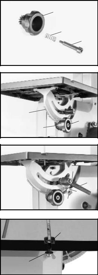
6. Locate pinion knob (N) Fig. 9, spring (O), and special screw (P).
7. Position pinion knob (N) Fig. 10, onto the back of saw so that the teeth on the pinion knob (N) engage the teeth on the trunnion (R). Fasten in place with special screw (P) and spring using the supplied 4mm wrench.
8.Fasten pointer (S) Fig. 11, to the back of band saw using the M5x.8x10mm pan head screw (T).
9.Place locking handle (F) Fig. 4, onto stud (G). Place spring (E) Fig. 4, inside hole of lock handle and fasten in place with screw (D) as shown in Fig. 11. NOTE: Handle
(F) is spring-loaded and can be repositioned on the stud by pulling out the handle and repositioning it on the nut.
10. Insert M6x1x30mm screw (W) Fig. 12, down through hole in table, as shown, and place an M6 flat washer (Z) onto the M6x1x30mm screw (W) and thread the M6x1 wing nut (X) onto screw (W) and tighten securely.
N
O
P
Fig. 9
R 
P
N
Fig. 10
D
F
S
T
Fig. 11
W
Z
X
Fig. 12
9
ATTACHING LAMP TO MACHINE
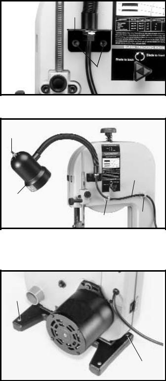
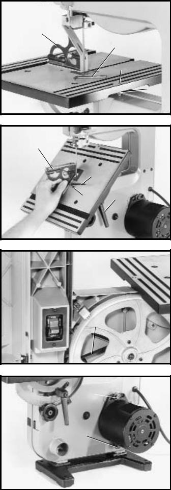
1.Fasten the lamp bracket (A) Fig. 13, to the top cover of the machine, using two M6x1x12mm cap head screws
(B) and 1/4" lockwashers as shown.
2.Peel backing from cord clamps (C) Fig. 13A, and apply one clamp at each of the locations shown. Make certain the lamp cord is routed out of the way of the blade, then secure cord (D) to cord clamps (C) as shown in Fig. 13A.
3.The flexible lamp operates independently of the band saw. To turn the lamp on and off, rotate switch (E) Fig. 13A.
 FIRE HAZARD: To reduce the risk of fire, use 40 watt or less, 120 volt, reflector track type light bulb (not supplied). A standard household light bulb should not be used. The reflector track type light bulb should not extend below the lamp shade.
A
B
Fig. 13
E
D
F
C
C
Fig. 13A
FASTENING BAND SAW
TO SUPPORTING SURFACE
A
 The machine must be secured to a supporting surface. Four holes are provided in the band saw base for this purpose, three of which are shown at
(A) Fig. 14.
 A
A
Fig. 14
10
OPERATING CONTROLS AND ADJUSTMENTS
THIS PRODUCT IS RECOMMENDED
FOR WOOD CUTTING ONLY.
STARTING AND |
|
|
STOPPING SAW |
|
|
The switch (A) Fig. 15, is located on the front side of the |
|
|
band saw. To turn the saw “ON” move the switch (A) up |
|
|
to the “ON” position. To turn the saw “OFF” move the |
A |
|
switch (A) down to the “OFF” position. |
||
|
Fig. 15
LOCKING SWITCH IN
THE “OFF” POSITION
IMPORTANT: When the tool is not in use, the switch should be locked in the “OFF” position to prevent unauthorized use. This can be done by grasping the switch toggle (B) Fig. 16, and pulling it out of the switch, as shown. With the switch toggle (B) removed, the switch will not operate. However, should the switch toggle be removed while the machine is running, the switch can be turned “OFF” once, but cannot be restarted without inserting the switch toggle (B).
B
Fig. 16
OPENING AND CLOSING DOOR
When making adjustments such as changing the blade, tracking the blade, blade guide adjustments, etc., the door
(B) Figs. 17 and 18, can be opened as follows:
 MOVING PARTS. LAZERATION / PINCH HAZARD: NEVER OPEN THE DOOR WHEN THE MACHINE IS RUNNING.
1.Press in the two locking latches (A) Fig. 17, and swing door (B) open.
2.Fig. 18, illustrates door (B) in open position.
3.To close and fasten door (B) Figs. 17 and 18, press on door directly over latches (A) Fig. 17, until latches snap into the locking position.
B
A
Fig. 17
B 
Fig. 18
11
ADJUSTING
BLADE TENSION
Blades of 1/8", 1/4", and 3/8" in width by 59-1/2" in length are available for use with your band saw. NOTE: The blade tension must be adjusted to accommodate different blade widths in order to provide proper blade tracking, cutting performance, and blade life.
 DISCONNECT MACHINE FROM POWER SOURCE.
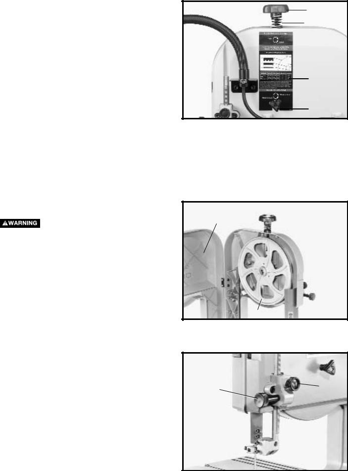
1.After the desired blade is assembled to the two wheels, turn tension knob (A) Fig. 19, clockwise until spring (B) begins to compress.
2.Turn tension knob (A) Fig. 19, an additional 2-1/2 turns for 1/8" wide blades; 3 turns for 1/4" wide blades; and 4 turns for 3/8" wide blades.
3.A chart (C) Fig. 19, is located at the rear of the band saw. This chart shows blade size, and the minimum radius that can be cut with each size blade.
TRACKING THE BLADE
DISCONNECT MACHINE FROM POWER
SOURCE.
1.Before tracking the blade, make sure the blade guides and blade support bearings are clear of the blade so as not to interfere with the tracking adjustment. Also make sure that the blade is tensioned properly. (Refer to section “ADJUSTING BLADE TENSION”).
2.Open the hinged door (C) Fig. 20.
3.Rotate upper wheel (A) Fig. 20, clockwise by hand and check to see if the blade (B) rides true on the approximate center of the two wheels.
4.If an adjustment is necessary, SLIGHTLY turn blade tracking knob (D) Fig. 19, clockwise to move the blade to the rear, and counterclockwise to move the blade to the front. NOTE: Turn the blade tracking knob (D) in small intervals to adjust the blade tracking.
ADJUSTING UPPER BLADE GUIDE ASSEMBLY
The upper blade guide assembly (A) Fig. 21, should always be no more than 1/8" above or as close as possible to the top surface of the workpiece being cut. Loosen knob (B) Fig. 21, rotate knob (C) and position the guide assembly (A) to the desired position. Then tighten knob (B).
A
B
C
D
Fig. 19
C
 B
B
A
Fig. 20
C  B
B
 A
A
Fig. 21
12
ADJUSTING UPPER BLADE GUIDES AND BLADE SUPPORT BEARING
IMPORTANT: BOTH THE UPPER AND LOWER BLADE GUIDES MUST BE PROPERLY ADJUSTED TO PREVENT THE BLADE FROM TWISTING DURING OPERATION.
DISCONNECT MACHINE FROM POWER
SOURCE.
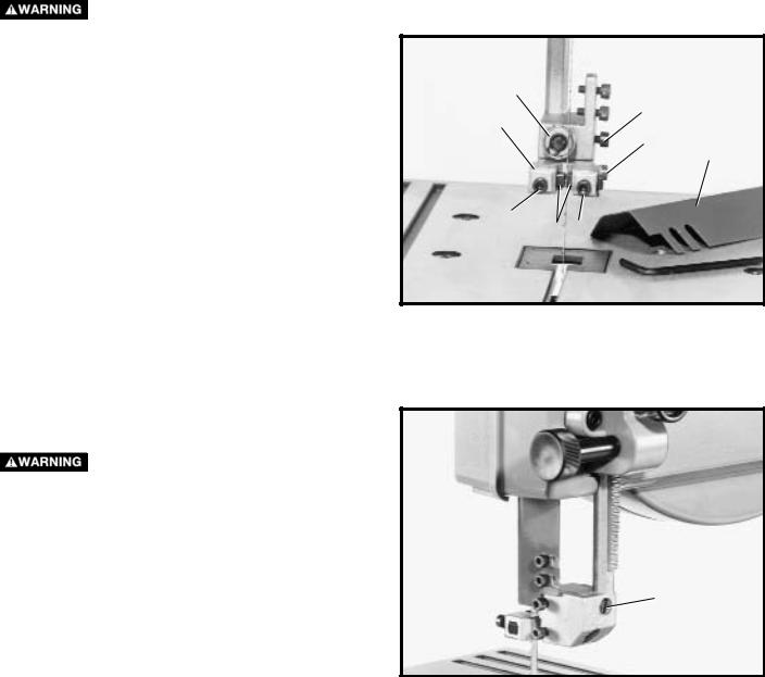
1.NOTE: Upper blade guard (B) Fig. 22, is shown removed for clarity.
2.Loosen the two screws (C) Fig. 22, and adjust the blade guides (D) as close as possible to the sides of the saw blade, being careful not to pinch the blade.Then tighten the two screws (C).
3.Loosen screw (E) Fig. 22, and move the guide bracket (F) in or out until the front edge of the guides (D) are just behind the “gullets” of the blade teeth. Then tighten screw (E).
4.The upper blade support/thrust bearing (G) Fig. 22, prevents the saw blade from being pushed back too far when cutting. The support bearing (G) should be adjusted approximately 1/32" behind the blade, so the back of the blade overlaps the outside diameter of the ball bearing by approximately 1/8". To adjust, proceed as follows:
DISCONNECT MACHINE FROM POWER
SOURCE.
5.Loosen screw (H) Fig. 22, and slide support bearing
(G) in or out until it is approximately 1/32" behind the saw blade.
6.The upper blade support bearing (G) Fig. 22, is set on an eccentric shaft. To change position of bearing (G), use a straight screwdriver, rotate shaft (J) Fig. 23, until the blade properly overlaps the support bearing. Then tighten screw (H).
G
H
F
E
B
C
D C
Fig. 22
J
Fig. 23
13
ADJUSTING LOWER BLADE GUIDES AND BLADE SUPPORT BEARING
The lower blade guides and blade support bearing should be adjusted at the same time as the upper guides and support bearings as follows:
DISCONNECT MACHINE FROM POWER
SOURCE.
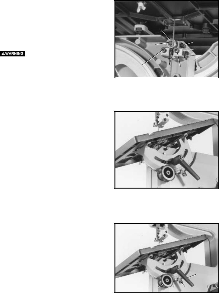
1.Loosen two screws (A) Fig. 24, and move guides (B) as close as possible to the sides of the blade, being careful not to pinch the blade. Then tighten the two screws (A).
2.The front edge of guide blocks (B) Fig. 24, should be adjusted so they are just behind the “gullets” of the blade teeth by loosening screw (C), and moving assembly (D) in or out as necessary. Then tighten screw (C).
3.The lower blade support bearing (E) Fig. 24, should be adjusted to support the rear of the blade during the cutting operation and also prevent the blade from being pushed too far to the rear which could damage the blade. The support bearing (E) Fig. 24, should be set about 1/32" behind the blade by loosening screw (F) Fig. 24, and moving shaft (G) in or out. Then tighten screw (F).
4.The lower blade support bearing (E) Fig. 24, should also be adjusted so the back of the blade overlaps the outside diameter of the ball bearing by approximately 1/8". The blade support bearing (E) is set on an eccentric shaft.To change position of bearing (E), loosen screw (F) Fig. 24, and rotate shaft (G) Figs. 24 and 25, until the blade properly overlaps the support bearing. Then tighten screw (F) Fig.24.
TILTING THE TABLE
The table can be tilted 45 degrees to the right. To tilt the table, loosen lock handle (A) Fig. 26, and turn knob (B) clockwise until desired angle is established. Then tighten lock handle (A). NOTE: The table lock handle (A) can be repositioned by pulling out on the handle and repositioning it on the nut located underneath the hub of the handle. A scale (C) and pointer (D) are provided to indicate the degree of tilt.
E
F
G
 D
D
C
A |
B |
A |
|
|
|
|
|
|
|
Fig. 24 |
|
 G
G
Fig. 25
 E
E
A
B C D
Fig. 26
14
ADJUSTING THE TABLE POSITIVE STOPS
Positive stops are provided for the table at the 90 and 45 degree angle to the blade. To check and adjust the positive stops, proceed as follows:
 DISCONNECT MACHINE FROM POWER SOURCE.
1.Tilt the table to the 90 degree position as shown in Fig. 27, and tighten lock handle (A) Fig. 28. Place a square (H) Fig. 27, on the table and against the blade and check to see if the blade is 90 degrees to the table surface. If an adjustment is necessary, proceed as follows:
2.Tilt the table slightly as shown in Fig. 26, to expose lock nut (E) Fig. 27. Loosen lock nut and return table to the 90° position. With the lock handle (A) Fig. 28 loose, turn adjusting screw (F) Fig. 27, using the wrench (G) provided until the blade is 90 degrees to the table. Then tighten lock nut (E) Fig. 27, and lock handle (A) Fig. 28.
3.Tilt the table to the 45 degree position as shown in Fig. 28. Place a square (H) on the table and against the blade and check to see if the blade is 45 degrees to the table surface. If an adjustment is necessary, proceed as follows:
4.Loosen lock nut on adjustment screw (J) Fig. 28, located on the underside of the table. With lock handle
(A) Fig. 28 loose, turn adjustment screw (J) using wrench
(G) provided until the blade is 45 degrees to the table. Then tighten lock handle (A), and lock nut on adjustment screw (J).
ADJUSTING BELT TENSION
If the drive belt on your band saw needs adjustment, proceed as follows:
 DISCONNECT MACHINE FROM POWER SOURCE.
The belt (A) Fig. 29, drives the blade wheel pulley from the motor pulley. The belt (A) is properly tensioned when there is approximately 1/4" deflection in the center span of the belt using light finger pressure. If belt tension needs to be adjusted, loosen two screws (B) Fig. 30, and rotate motor accordingly. Tighten screws (B) when adjustment is completed.
H
G
F
E
Fig. 27
H
G
J A
Fig. 28
A
Fig. 29
B
B
Fig. 30
15

CHANGING BLADES
 DISCONNECT MACHINE FROM POWER SOURCE.
To change blades:
1.Press in door latches (A) Fig. 34, and open door (B) as shown.
2.Loosen two screws (C) Fig. 35, and remove blade guard (D).
3.Release tension on the band saw blade by turning tension knob (E) Fig. 34 counterclockwise.
4.Remove table alignment screw (F) Fig. 36.
5.Slip the blade off both wheels and guide it out through the slot in the table.
6.Check the new blade to make sure that the teeth will point down toward the table when installed. IF NOT, CAREFULLY TURN BLADE INSIDE OUT.
7.Place the new blade onto wheels and adjust blade tension, blade guides and tracking as described previously in this manual.
8. Replace blade guard, which was removed in STEP 2, and table alignment screw which was removed in
STEP 4.
9. Close door (B) Fig. 34, before operating saw.
|
E |
C |
|
|
|
A |
|
D |
B 
A 
Fig. 35
Fig. 34
DUST CHUTE
A dust collection system can be attached to the 13/4 " O.D. dust chute (A) Fig. 37.
WRENCH STORAGE |
F |
The 3mm and 4mm wrenches (A) supplied with your band saw can be stored inside the wheel cover as shown in Fig. 37A.
Fig. 36
A
A
Fig. 37 |
Fig. 37A |
16
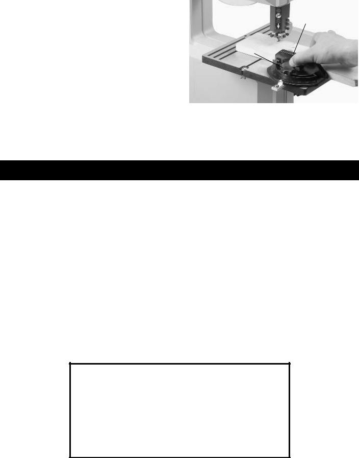
MITER GUAGE (OPTIONAL) |
|
Some Shopmaster Band Saws come with a miter gauge. |
B |
If your machine has a miter gauge, you can adjust it up |
|
to 45 degrees, right and left. Loosen the lock knob (A), |
|
rotate the miter gauge body (B) and tighten the lock knob |
|
(A). |
A |
Fig. 38 illustrates a typical cross-cutting operation using |
|
the accessory miter gauge. Notice how the upper blade |
|
guide assembly is set slightly above the work surface. |
|
|
|
|
Fig. 38 |
OPERATING THE BAND SAW
Before starting the machine, see that all adjustments are properly made and the guards are in place. Turn the upper wheel by hand to make sure that everything is correct BEFORE turning on the power.
Keep the top guide within 1/8" of the work piece at all times. Do not force the material against the blade. Light pressure on the work piece will produce a smoother cut, and prevent excess friction, heating, and hardening of the blade.
KEEP THE SAW BLADE SHARP. Very little forward pressure is required for normal cutting. Keep the workpiece moving at a slow and consistent rate against the blade to ensure a smooth and accurate cut.
Avoid twisting the blade by trying to turn sharp corners. Remember, you must saw around corners.
CUTTING CURVES
 CUT HAZARD: Keep hands away from blade.
When cutting curves, turn the stock carefully so that the blade follows without twisting. If a curve is so abrupt that it is necessary to repeatedly back up and cut a new kerf, a narrower blade, a blade with more set, or additional relief cuts Fig. 39, may be necessary to allow the blade to cut more efficiently. The more set a blade has, the easier it will allow the stock to be turned, but the cut is usually rougher than where a medium amount of set is used.
When withdrawing the piece being cut, changing the cut, or for any other reason, be careful not to accidentally draw the blade off the wheels. In most cases, it is easier and safer to turn the stock and saw out through the waste material, rather than try to withdraw the stock from the blade.
Fig. 39
17
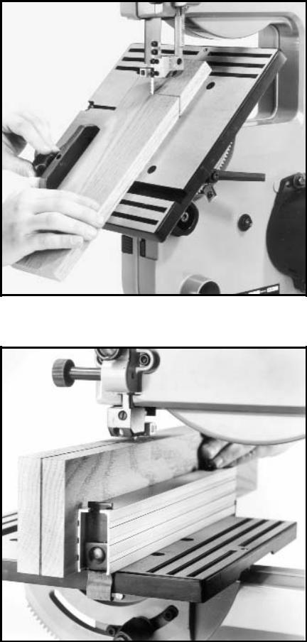
Fig. 40
Fig. 40 illustrates a typical bevel cutting operation using the accessory miter gage.
Fig. 41
Fig. 41 illustrates a typical resawing application using the accessory rip fence.
18

TROUBLESHOOTING GUIDE
In spite of how well a band saw is maintained, problems can occur. The following troubleshooting guide will help you solve the more common problems:
Trouble: SAW WILL NOT START.
Probable Cause
1.Saw not plugged in.
2.Fuse blown or circuit breaker tripped.
3.Cord damaged.
Remedy
1.Plug in saw.
2.Replace fuse or reset circuit breaker.
3.Have cord replaced.
Trouble: BREAKER KICKS OUT FREQUENTLY.
Probable Cause |
Remedy |
1.Extension cord too light or too long.
2.Feeding stock too fast.
3.Blade in poor condition (dull, warped, gummed).
4.Low voltage supply.
1.Replace with adequate size cord.
2.Feed stock more slowly.
3.Clean or replace blade.
4.Contact your electric company.
Trouble: BAND SAW VIBRATES EXCESSIVELY. |
|
|
|
Probable Cause |
Remedy |
||
1. |
Machine not mounted securely to workbench. |
1. |
Tighten all mounting hardware. |
2. |
Bench on uneven surface. |
2. |
Reposition on flat level surface. |
3. |
Worn belt. |
3. |
Replace belt. |
4. |
Belt not tensioned correctly. |
4. |
Adjust belt tension by moving motor. |
5. |
Motor not fastened securely. |
5. |
Tighten all mounting hardware. |
Trouble: BAND SAW DOES NOT COME UP TO SPEED. |
|
|
|
Probable Cause |
Remedy |
||
1. |
Low voltage due to improper extension cord size. |
1. |
Replace with adequate size cord. |
2. |
Low voltage. |
2. |
Contact your electric company. |
Trouble: BLADES BREAK.
Probable Cause
1.Blade not tensioned properly.
2.Blade guides improperly adjusted.
3.Blade support bearing improperly adjusted.
4.Blade wheel tracking adjustment improperly set.
5.Bad weld on blade.
6.Worn tires.
7.Forcing wide blade around short radius.
8.Dull blade or insufficient set.
9.Upper blade guide set too high.
10.Continuous running of machine when not actually cutting.
Remedy
1.Adjust blade tension.
2.Check and adjust blade guides.
3.Adjust blade support bearing.
4.Check and adjust blade tracking.
5.Replace the blade.
6.Replace tires.
7.Change to a narrower blade.
8.Replace blade.
9.Set upper blade guide within 1/8" of workpiece.
10.Turn off machine when not performing cutting operation.
(continued on next page)
19
|
TROUBLESHOOTING GUIDE |
||
|
|
(CONTINUED) |
|
|
|
|
|
Trouble: BLADE WILL NOT TRACK. |
|
|
|
Probable Cause |
Remedy |
||
1. |
Blade too loose |
1. |
Adjust tension |
2. |
Upper wheel not properly adjusted. |
2. |
Adjust upper wheel. |
3. |
Improperly adjusted blade support bearing. |
3. |
Adjust blade support bearing. |
Trouble: CUT DOES NOT AGREE WITH SETTING ON THE TILT SCALE. |
|||
Probable Cause |
Remedy |
||
1. |
Pointer out of adjustment |
1. |
Adjust pointer. |
Trouble: BLADE WILL NOT STAY ON WHEEL.
Probable Cause
1.Blade not tensioned properly.
2.Blade guides improperly adjusted.
3.Blade support bearing improperly adjusted.
4.Blade wheel not tracking properly.
5.Bad weld on blade.
6.Worn tires.
Trouble: BAND SAW MAKES UNSATISFACTORY CUTS.
Probable Cause
1.Blade not tensioned properly.
2.Blade guides improperly adjusted.
3.Blade support bearing improperly set.
4.Blade wheel not tracking properly.
5.Bad weld on blade.
6.Worn tires.
7.Incorrect blade for work being done.
8.Dull blade or insufficient set.
9.Upper blade guide set too high.
10.Continuous running of machine when not actually cutting.
Remedy
1.Adjust blade tension.
2.Check and adjust blade guides.
3.Adjust blade support bearing.
4.Check and adjust blade tracking.
5.Replace the blade.
6.Replace tires.
Remedy
1.Adjust blade tension.
2.Check and adjust blade guides.
3.Adjust blade support bearing.
4.Check and adjust blade tracking.
5.Replace the blade.
6.Replace tires.
7.Change the blade.
8.Replace blade.
9.Set upper blade guide within 1/8" of work piece.
10.Turn off machine when not performing cutting operation.
20
BAND SAW BLADES
A band saw blade is a delicate piece of steel that is subjected to tremendous strain. You can obtain long use from a band saw blade if you use it properly. Be sure you use blades of the proper thickness, width and temper for the various types of material and cuts.
Always use the widest blade possible. Use narrow blades only for sawing small, abrupt curves and for fine, delicate work. This will save blades and will produce better cuts. For cutting wood and similar materials, Shopmaster offers blades in widths of 1/8", 1/4", and 3/8".
Any one of a number of conditions may cause a band saw blade to break. Blade breakage is, in some cases, unavoidable, being the natural result of the peculiar stresses to which blades are subjected. Blades will brake often due to avoidable causes, such as the lack of care to the blade or the blade not being properly adjusted to the band saw. The most common causes of blade breakage are:
(1)faulty alignments and adjustments of the guides.
(2)forcing or twisting a wide blade around a curve of short radius.
(3)feeding the work piece to fast into the blade.
(4)dullness of the teeth, or absence of sufficient set.
(5)excessive tensioning of the blade.
(6)top guide set too high above the work piece being cut.
(7)using a blade with a lumpy or improperly finished braze or weld.
(8)continuous running of the saw blade when the blade is not in use.
Use blades that are 59-1/2" in length on this machine.
Always use a sharp blade. Keep it free from gum and pitch. Clean frequently with a stiff fiber brush.
Narrow blades are used for cutting small circles or curves while the wider blades are best suited for straight cutting such as ripping.
A new blade, in most cases, will perform better and last longer than a re-sharpened blade.
Insure that the blade guides are adjusted properly.
Do not force or twist the blade around a curve or a very short radius.
Feed the workpiece through the blade at a consistent rate, allow the blade to do the cutting – do not feed the work piece too fast.
Do not apply excessive tension to the blade. The tension is only necessary to drive the blade without slipping on the wheels. Narrow blades require less tension than wider blades.
21

NOTES
22
 Loading...