


R18448
T
E
F
L
O
N
ASME A112.18.1 / CSA B125.1
®
®
U
P
C
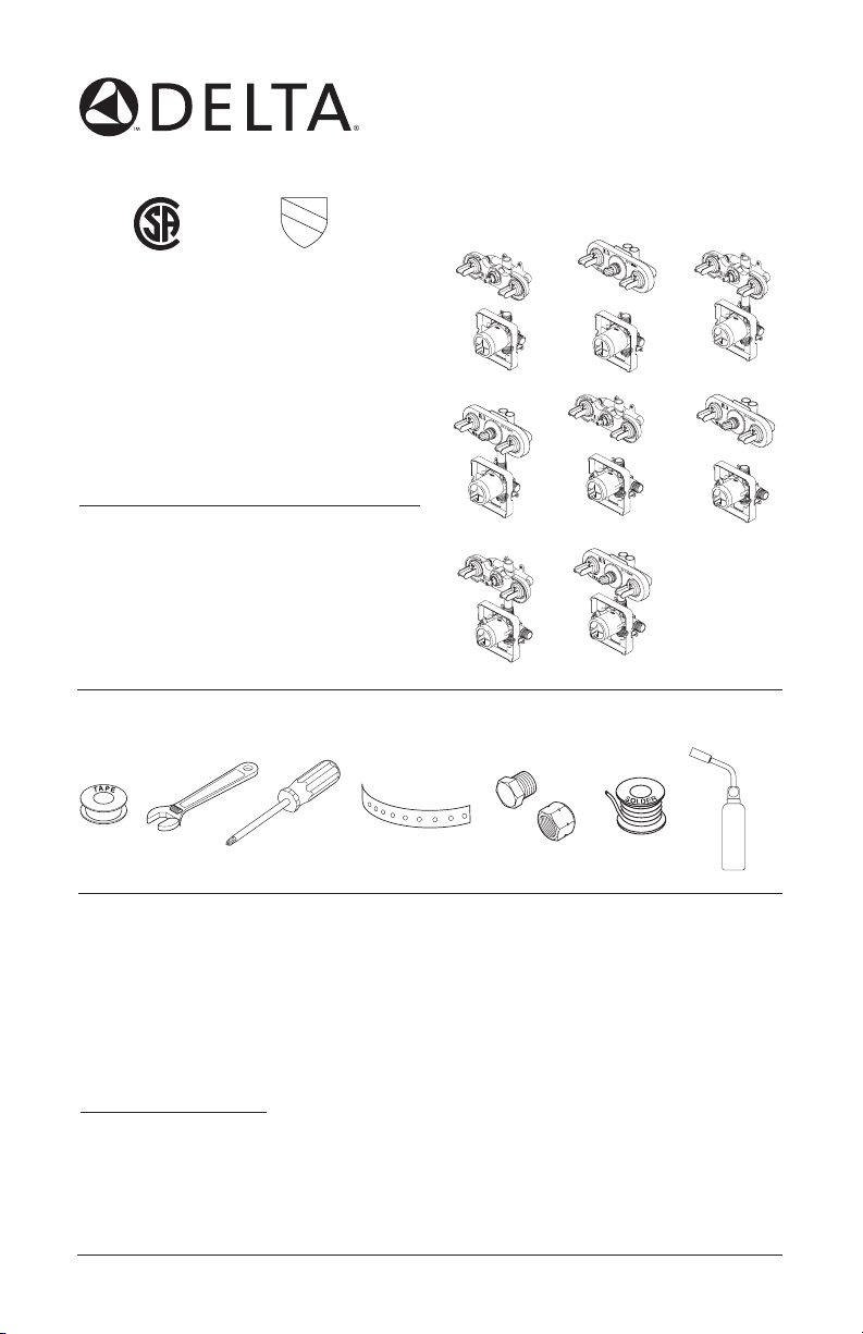
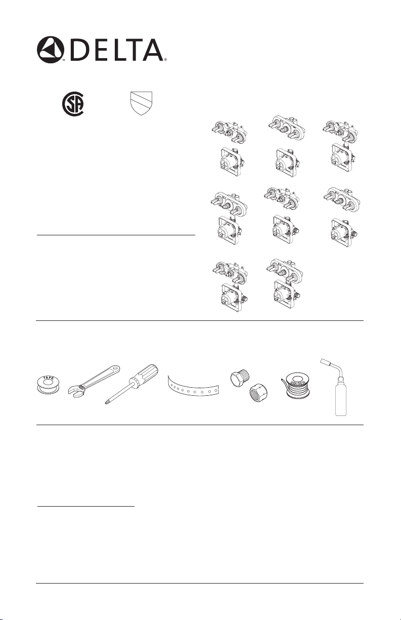
Models
R18222, R18224,
R18442 & R18448
Series
Write purchased model number here.
You may need the following tools:
SINGLE HANDLE
MULTICHOICE™ UNIVERSAL
JETTED SHOWER™ &
JETTED SHOWER XO™
ROUGH-IN VALVE BODY
For easy installation of your Delta® faucet you will need:
• To READ ALL the instructions completely before beginning.
• To READ ALL warnings, care, and maintenance information.
THIS ROUGH-IN BODY MEETS OR EXCEEDS THE FOLLOWING STANDARDS:
ANSI A112.18.1 &
ASME A112.18.1 / CSA B125.1
.
NOTICE TO INSTALLER: CAUTION!–As the installer of this rough-in body, it is your
responsibility to properly INSTALL this rough-in body per the instructions given.
YOU MUST inform the owner/user of this requirement by following the instructions.
If you or the owner/user are unsure how to properly install this rough-in body, please refer
to the instructions supplied and if still uncertain, call us at 1-800-345-DELTA. Leave this
Instruction Sheet for the owner's/user's reference.
6/27/07
1
51045 Rev B

TABLE OF CONTENTS:
Warranty -- - -- --- - - -- --- - - -- --- - - -- --- - - -- --- - - -- --- - - -- --- - - -- --- - - -- Page 2
Installation Instructions - - -- - --- -- -- - -- - -- -- - -- - -- -- - -- - --- -- -- - -- - -- -- Pages 3 -9
Replacement Parts - - --- -- -- - -- - -- -- - -- - -- -- - -- - --- -- -- - -- - -- -- - -- - -- Pages 1 0- 13
Lifetime Faucet and Finish Limited Warranty
All parts and finishes of the Delta® faucet are
warranted to the original consumer purchaser to
be free from defects in material & workmanship
for as long as the original consumer purchaser
owns their home. Delta Faucet Company
recommends using a professional plumber for all
installation & repair.
Delta will replace, FREE OF CHARGE, during
the warranty period, any part or finish that proves
defective in material and/or workmanship under
normal installation, use & service. Replacement
parts may be obtained by calling 1-800-345DELTA (in the U.S. and Canada) or by writing to:
In the United States:
Delta Faucet Company
Product Service
55 E. 111th Street
Indianapolis, IN 46280
In Canada:
Delta Faucet Canada
Technical Service Centre
420 Burbrook Place
London, ON N6A 4L6
This warranty is extensive in that it covers
replacement of all defective parts and even
finish, but these are the only two things that
are covered. LABOR CHARGES AND/OR
DAMAGE INCURRED IN INSTALLATION,
REPAIR, OR REPLACEMENT AS WELL AS ANY
OTHER KIND OF LOSS OR DAMAGES ARE
EXCLUDED. Proof of purchase (original sales
receipt) from the original consumer purchaser
must be made available to Delta for all warranty
claims. THIS IS THE EXCLUSIVE WARRANTY
BY DELTA FAUCET COMPANY, WHICH DOES
NOT MAKE ANY OTHER WARRANTY OF ANY
KIND, INCLUDING THE IMPLIED WARRANTY
OF MERCHANTABILITY.
This warranty excludes all industrial, commercial
& business usage, whose purchasers are
hereby extended a five year limited warranty
from the date of purchase, with all other terms
of this warranty applying except the duration of
the warranty. This warranty is applicable to Delta
faucets manufactured after January 1, 1995.
Some states/provinces do not allow the exclusion
or limitation of incidental or consequential
damages, so the above limitation or exclusion
may not apply to you. Any damage to this faucet
as a result of misuse, abuse, or neglect, or any
use of other than genuine Delta® replacement
parts WILL VOID THE WARRANTY.
This warranty gives you specific legal rights, and
you may also have other rights which vary from
state/province to state/province. It applies only
®
faucets installed in the United States of
for Delta
America, Canada, and Mexico.
®
© 2007 Masco Corporation of Indiana
2
1
R18222
5
1
4
R18222-WS
R18224
3
2
3
A
B
4
3
5
1
A
B
R18224-WS
R18442 & R18448
5
1
2
3
4
R18442-WS &
3
2
3
A
B
R18448-WS
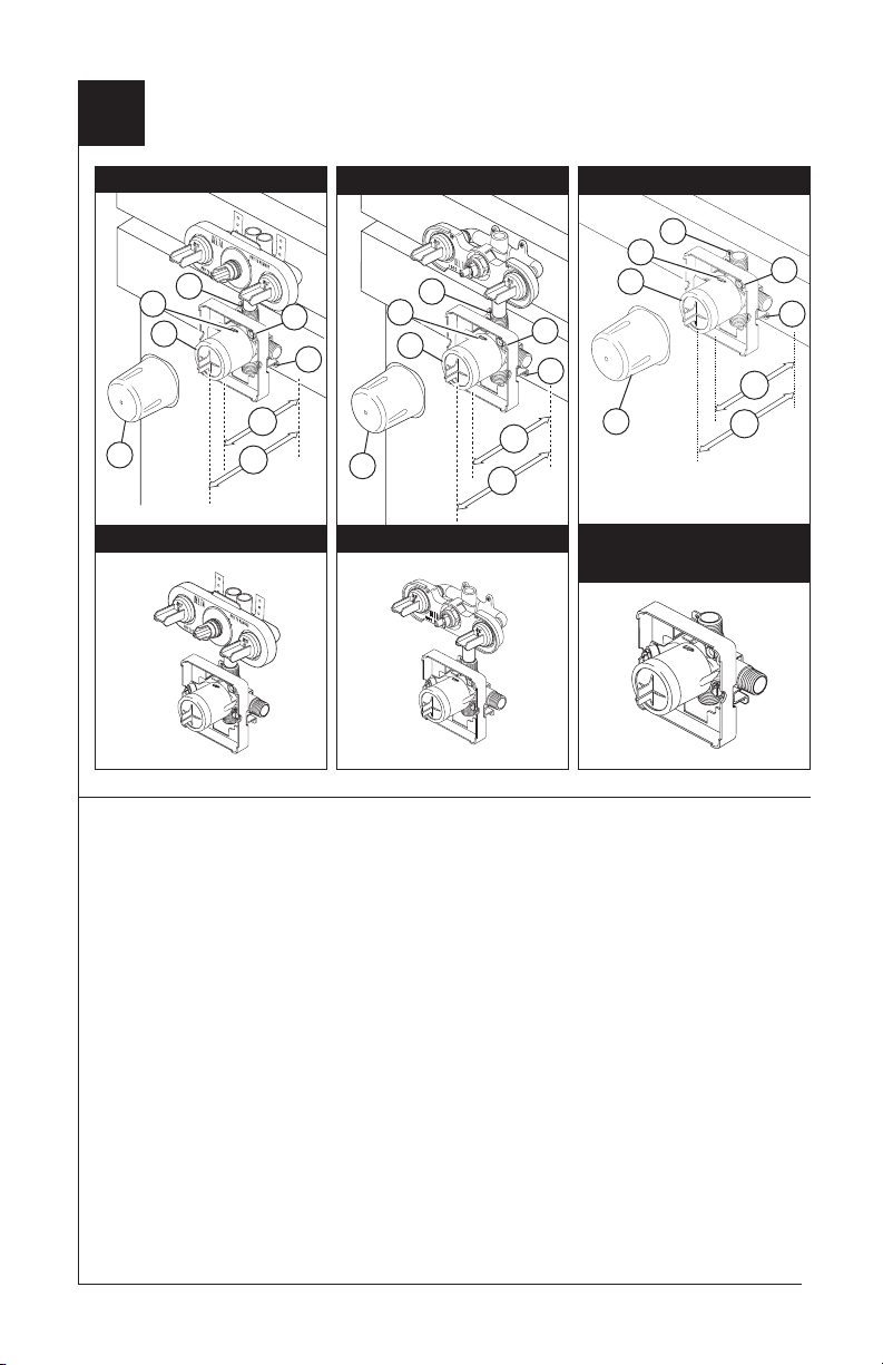
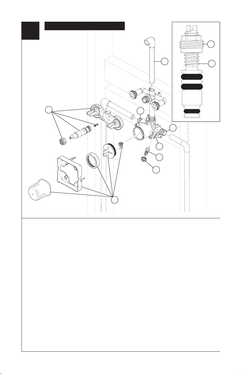
Jetted Shower™ and Jetted Shower XO™ Installation
Description:
Jetted Shower™ valves turn the body
jets on and off only. Jetted Shower XO™
valves divert the water to the jets, the
showerhead, an extra port or any
combination of two, making it a 3 port, 6
function diverter. The black stem
extender (without the stop) must be used
if using all outlets. If a 2 port, 3 function
diverter is desired, jets only, combination
jets & showerhead and showerhead
only, the plug must be soldered in as
shown and the blue stem extender with
the stop must be used.
Installation Instructions:
Shut off water supplies. Consider the
type and thickness of your finished wall
before placing your stringer back plate.
Mount the valve to desired height. We
recommend 52" from the base of the
enclosure to the center line of the jets.
Install the body (1) so the surface of the
finished wall is flush with the front of the
plasterguard (2), using the two stringer
mounting holes (3) on the bracket. Note:
Remove cover (4) to access mounting
holes. Make sure the word “UP” (5) is on
top of the valve body when installing.
Distance (A) from the stringer to the
front of the plasterguard is 2.8" (71 mm).
Distance (B) from the stringer to the front
of the bonnet is 3.9" (99 mm).
If a thin wall is used, be sure to have the
plasterguard behind the wall, otherwise
the wall should always be flush with the
front of the plasterguard. Note: For thin
wall mounting, use included template
for hole location.
3
2
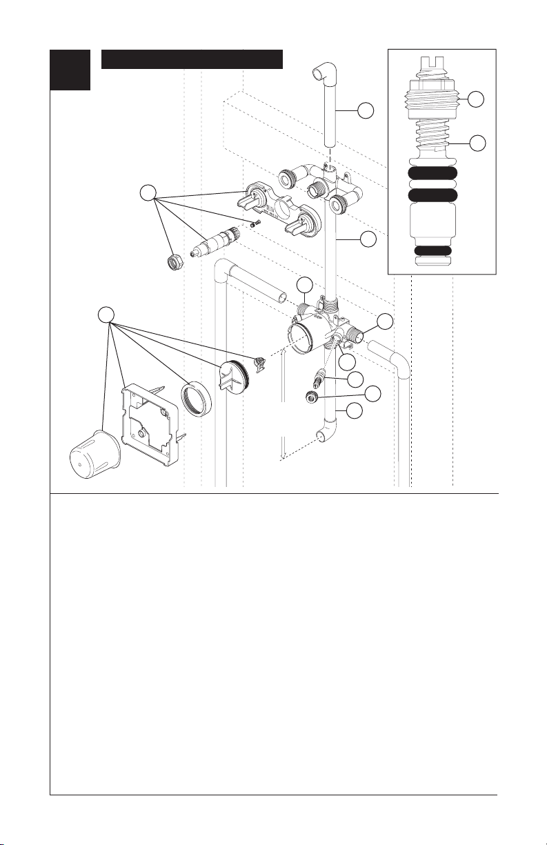
R18448 & R18448-WS
8
6
9
1
5
4
2
16"
(406 mm)
Max
R18448 & R18448-WS Installation
Remove the bonnet nut, stem and stem
extender, seat, spring, and plasterguard
(1), plus, the screen, test cap, bonnet nut,
plasterguard and cover (2) before soldering.
Connect valve body to water supplies using
er fittings. Note: (3) is the cold
the prop
inlet port and (4) is the hot inlet port.
Solder a copper tube (5) from the valve
body to the jet module so the jets are at
the desired height. Solder another tube (6)
onto the top of the jet module to the shower
arm elbow to the desired height. It is
recommended to mount valves to stringers
as shown.
The pipe (7) between valve & tub spout
must be a minimum of 1/2" (13 mm) copper
pipe or 1/2" (13 mm) iron pipe in a straight
drop no less than 8" (203 mm) but no more
than 16" (406 mm) long with only one 90
degree elbow to the spout nipple. If any
outlet port is to be unused, seal the port with
a pipe plug.
If you are making a back to back or reverse
installation (hot on right and cold on left)
install the valve body as described, but
reverse the water supply lines.
After soldering, reinstall all parts in reverse
order; ensure bonnet nuts are tightened
securely. Then install the stops into the body;
be careful not to overtighten the nuts.
Note: Install stops in the w/stops version as
follows: Thread nut (8) on stem (9) as shown.
Then press stem and nut assembly into body
(10) and tighten using a 3/8", 6 point, deep
well socket. With a flat head screwdriver, adjust
stem clockwise to close and counterclockwise
to open.
3
10
9
8
7
4
2
R18442 & R18442-WS
3 Port, 6 Function
Installation
9
7
5
1
4
2 Port, 3 Function
Installation
7
6
2
16"
(406 mm)
Max
R18442 & R18442-WS Installation
Remove the bonnet nut, cartridge and
plasterguard (1), plus, the screen, test cap,
bonnet nut, plasterguard and cover (2) before
soldering. Connect valve body to water
supplies using the prop
er fittings. Note: (3)
is the cold inlet port and (4) is the hot
inlet port.
Solder a copper tube (5) from the valve
body to the jet module so the jets are at the
desired height. Determine whether a three
or six function configuration is desired. For
2 port, 3 function; solder plug into auxiliary
port (6) in casting. Solder tube (7) into the
main port of the jet module to the shower
arm elbow to the desired height. For 3 port,
6 function; all outlet ports are used. It is
recommended to mount valves to stringers
as shown.
The pipe (8) between valve & tub spout must
be a minimum of 1/2" (13 mm) copper pipe
or 1/2" (13 mm) iron pipe in a straight drop
no less than 8" (203 mm) but no more than 16"
(406 mm) long with only one 90 degree elbow
to the spout nipple. If any outlet port is to be
unused, seal the port with a pipe plug.
If you are making a back to back or reverse
installation (hot on right and cold on left) install
the valve body as described, but reverse the
water supply lines.
After soldering press the detent (9) into proper
hole as shown, reinstall all parts in reverse
order; ensure bonnet nuts are tightened
securely. Then install the stops into the body;
be careful not to overtighten the nuts.
Note: Install stops in the w/stops version as
follows: Thread nut (10) on stem (11) as shown.
Then press stem and nut assembly into body
(12) and tighten using a 3/8", 6 point, deep
well socket. With a flat head screwdriver, adjust
stem clockwise to close and counterclockwise
to open.
3
12
11
10
8
10
11
5
2
R18224 & R18224-WS
6
1
2
4
R18224 & R18224-WS Installation
Remove the bonnet nut, stem and stem
extender, seat, spring, and plasterguard
(1), plus, the screen, test cap, bonnet nut,
plasterguard and cover (2) before soldering.
Connect valve body to water supplies using
er fittings. Note: (3) is the cold
the prop
inlet port and (4) is the hot inlet port.
Solder a tube (5) onto the top of the jet
module to the shower arm elbow to the
desired height. If any outlet port is to be
unused, seal the port with a pipe plug. It
is recommended to mount unit to stringers
as shown.
If you are making a back to back or reverse
installation (hot on right and cold on left),
install the valve body as described, but
reverse the water supply lines.
After soldering reinstall all parts in reverse
order; ensure bonnet nuts are tightened
securely. Then install the stops into the body;
be careful not to overtighten the nuts.
Note: Install stops in the w/stops version as
follows: Thread nut (6) on stem (7) as shown.
Then press stem and nut assembly into body
(8) and tighten using a 3/8", 6 point, deep well
socket. With a flat head screwdriver, adjust
stem clockwise to close and counterclockwise
to open.
5
3
8
7
6
7
6
2
R18222 & R18222-WS
2 Port, 3 Function
Installation
5
5
3 Port, 6 Function
Installation
7
1
4
10
9
8
2
R18222 & R18222-WS Installation
Remove the bonnet nut, cartridge and
plasterguard (1), plus, the screen, test
cap, bonnet nut, plasterguard and cover
(2) before soldering.
to water supplies using the prop
Note: (3) is the cold inlet port and (4) is
the hot inlet port.
Solder a tube (5) from main outlet of the
jet module to the shower arm elbow to the
desired height.
or six function configuration is desired. For
2 port, 3 function; solder plug into auxiliary
port (6) in casting. For 3 port, 6 function;
all outlet ports are used. It is recommended
to mount valves to stringers as shown.
If you are making a back to back or reverse
installation (hot on right and cold on left)
Connect valve body
er fittings.
Determine whether a three
install the valve body as described, but
reverse the water supply lines.
After soldering press in the detent (7) into
proper hole as shown, reinstall all other parts
in reverse order; ensure bonnet nuts are
tightened securely.
into the body; be careful not to overtighten
the nuts.
Note: Install stops in the w/stops version as
follows: Thread nut (8) on stem (9) as shown.
Then press stem and nut assembly into body
(10) and tighten using a 3/8", 6 point, deep
well socket. With a flat head screwdriver, adjust
stem clockwise to close and counterclockwise
to open.
6
8
3
9
Then install the the stops
7
3
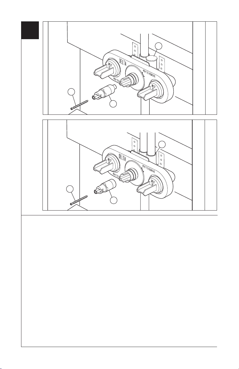
Blue Stem Extender -
2 Port, 3 Function Installation
3
1
2
Black Stem Extender -
3 Port, 6 Function Installation
3
1
4
Stem Extender Installation
Be sure to install the proper stem
extender for your installation.
required stem extender onto brass stem.
Install the blue stem extender (2) if the
Place
installation does not use the auxillary port (3).
Install the black stem extender (4) if the
installation uses all of the outlet ports. Use
screw (1) to secure.
8
4
1
2
2
1
1
1
2
2
1
2
2
1
1
1
2
2
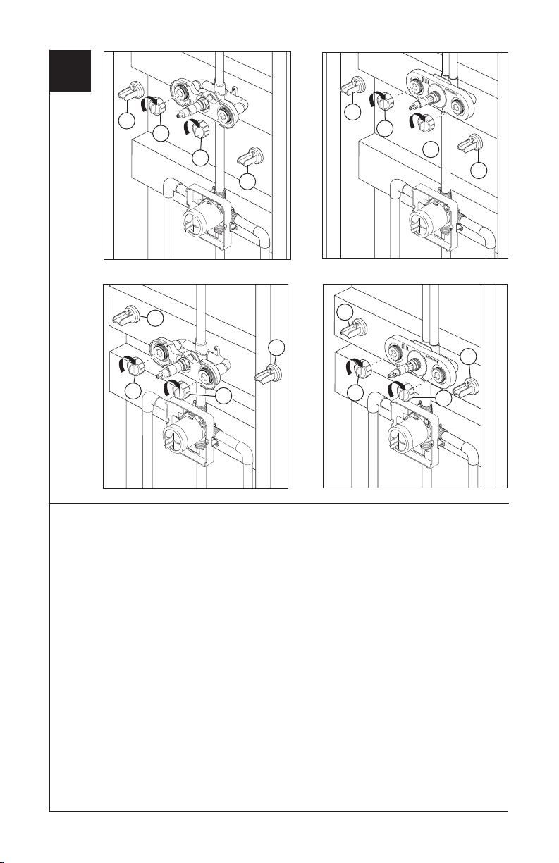
Pressure Testing & Flushing the Installation
Prior to testing, break off plasterguard caps
(1) and completely thread on the pressure
testing caps (2). Ensure the bonnet nuts
are properly tightened, and plug both
outlets with proper fittings. Check for leaks.
After testing remove shower and/or tub spout
plug and flush system. After flushing remove
filter screen (see step 2) and reinstall cap,
bonnet and cover.
9

Notes / Notas / Notes
T
E
F
L
O
N
ASME A112.18.1 / CSA B125.1
®
®
U
P
C
Modelos
R18222, R18224,
R18442 & R18448
Series
Escriba aquí el número del modelo comprado.
CUERPO DE LA VÁLVULA PARA
LA INSTALACIÓN PRELIMINAR
DE LAS REGADERAS DE
UNA MANIJA MULTICHOICE™
UNIVERSAL JETTED SHOWER™
Y JETTED SHOWER XO™
Usted puede necesitar:
Para instalación fácil de su llave Delta® usted necesitará:
• LEER TODAS las instrucciones completamente antes de empezar
• LEER TODOS los avisos, cuidados, e información de mantenimiento.
ESTA VALVULA CUMPLE O EXCEDE LAS SIGUIENTES NORMAS: ANSI A112.18.1 y
ASME A112.18.1 / CSA B125.1
AVISO AL INSTALADOR: ¡PRECAUCIÓN!- Como instalador de la tubería interna -
dentro de la pared/piso, es su responsabilidad INSTALAR esta pieza correctamente
como se describe en las instrucciones que le damos. USTED DEBE informarle al
propietario/usuario, siguiendo las instrucciones dadas, de este requisito. Si usted o el
propietario/usuario no están seguros como se instalan correctamente las tuberías internas,
por favor refiérase a las instrucciones proporcionadas y si todavía no está seguro, llámenos
al 1-800-345-DELTA. Deje esta hoja de instrucciones como referencia para el
propietario/usuario.
6/27/07
.
1
51045 Rev B
 Loading...