


1-1/2 H.P.
Dust Collector
Recolector de polvo de 1-1/2 H.P.
1-1/2 H.P.
Dépoussiéreur
Français (17)
Español (33)
www.deltaportercable.com
Instruction manual
Manuel d’utilisation
Manual de instrucciones
INSTRUCTIVO DE OPERACIÓN, CENTROS
DE SERVICIO Y PÓLIZA DE GARANTÍA.
 LÉASE ESTE INSTRUCTIVO
ANTES DE USAR EL PRODUCTO.
50-786

TABLE OF CONTENTS
IMPORTANT SAFETY INSTRUCTIONS |
......................2 |
MAINTENANCE.............................................................. |
14 |
|
safety guidelines - definitions....................... |
2 |
SERVICE......................................................................... |
15 |
|
FUNCTIONAL DESCRIPTION....................................... |
6 |
ACCESSORIES............................................................... |
16 |
|
CARTON CONTENTS.................................................... |
6 |
WARRANTY |
16 |
|
assembly |
7 |
|||
FranÇais |
17 |
|||
operation |
13 |
|||
ESPAÑOL |
33 |
|||
TROUBLESHOOTING |
14 |
|||
|
|
IMPORTANT SAFETY INSTRUCTIONS
 Read all warnings and operating instructions before using any tool or equipment. When using tools or equipment, basic safety precautions should always be followed to reduce the risk of personal injury. Improper operation, maintenance or modification of tools or equipment could result in serious injury and property damage. There are certain applications for which tools and equipment are designed. This product should NOT be modified and/or used for any application other than for which it was designed.
If you have any questions relative to its application DO NOT use the product until you have written DELTA Machinery and we have advised you. Contact us online at www.deltaportercable.com or by mail at End User Services, DELTA Machinery, 4825 Highway 45 North, Jackson, Tennessee 38305. In Canada,125 Mural St. Suite 300, Richmond Hill, ON, L4B 1M4)
Information regarding the safe and proper operation of this tool is available from the following sources:
•Power Tool Institute, 1300 Sumner Avenue, Cleveland, OH 44115-2851or online at www.powertoolinstitute.com
•National Safety Council, 1121 Spring Lake Drive, Itasca, IL 60143-3201
•American National Standards Institute, 25 West 43rd Street, 4 floor, New York, NY 10036 www.ansi.org - ANSI 01.1 Safety Requirements for Woodworking Machines
•U.S. Department of Labor regulations www.osha.gov
SAVE THESE INSTRUCTIONS!
SAFETY GUIDELINES - DEFINITIONS
It is important for you to read and understand this manual. The information it contains relates to protecting YOUR SAFETY and PREVENTING PROBLEMS. The symbols below are used to help you recognize this information.
 indicates an imminently hazardous situation which, if not avoided, will result in death or serious injury.
 indicates a potentially hazardous situation which, if not avoided, could result in death or serious injury.
 Indicates a potentially hazardous situation which, if not avoided, may result in minor or moderate injury.
NOTICE |
indicates a practice not related to personal injury which, if not avoided, may result in property |
damage.
IMPORTANT SAFETY INSTRUCTIONS
When using the dust collector, basic precautions should always be followed, including the following:
READ ALL INSTRUCTIONS BEFORE
USING DUST COLLECTOR


 To reduce the risk of fire, electric shock, or injury:
 FIRE AND EXPLOSION HAZARD. Do not use this unit to filter metal dust. Combining wood and metal dust can create an explosion or fire hazard. This unit is intended to filter non-explosive atmospheres only.


 FIRE AND EXPLOSION HAZARD. Do not use this unit to dissipate fumes or smoke. Explosions or fire can result. This dust collector is intended for use where only dry airborne dust is present. Its use should be limited to nonexplosive, non-metallic atmospheres.
 FIRE AND EXPLOSION HAZARD. Do not use the dust collector to pick up flammable liquids such as gasoline. Do not use the dust collector near flammable or combustible liquids. Explosion and/or fire can occur.
 FIRE HAZARD. When using this dust collector, do not pick up anything that is burning, smoldering, or smoking (matches, cigarettes, or hot ashes).
 EXPLOSION HAZARD. Do not use this unit to vacuum combustible explosive materials (coal, grain, or other finely-divided combustible material).
 HEALTH HAZARD. Do not use this unit to vacuum hazardous, toxic, or carcinogenic materials (asbestos,
pesticide, or lead-based paint debris).
2

•Do not leave dust collector when plugged in. Unplug from outlet when not in use and before servicing.
• To reduce the risk of electric shock, do not use outdoors or on wet surfaces.
•Do not allow to be used as a toy. Close attention is necessary when used by or near children.
•Use only as described in this manual. Use only manufacturer’s recommended attachments.
•Do not use with damaged cord or plug. If dust collector is not working as it should, has been dropped, damaged, left outdoors, or dropped into water, return it to a service center.
•Do not pull or carry by cord, use cord as a handle, close a door on cord, or pull cord around sharp edges or corners. Do not run dust collector over cord. Keep cord away from heated surfaces.
•Do not unplug by pulling on cord. To unplug, grasp the plug, not the cord.
•Do not handle plug or dust collector with wet hands.
•Do not put any object into openings. Do not use with any opening blocked; keep free of dust, lint, hair, and anything that may reduce air flow.
•Keep hair, loose clothing, fingers, and all parts of body away from openings and moving parts.
•Turn off all controls before unplugging.
•Do not operate this unit until it is completely assembled and installed according to the instructions.
A unit incorrectly assembled can cause injury.
•Obtain advice from your supervisor, instructor, or another qualified person if you are not thoroughly familiar with the operation of this unit. Knowledge is safety
•Follow all wiring codes and recommended electrical connections to prevent electrical shock or electrocution.
•Do not pull this unit by the power cord. Do not allow the power cord to come in contact with sharp instruments or edges, hot surfaces, or oil or grease.
Do not place any weight on top of the power cord. A damaged power cord can cause electrical shock or electrocution.
•Maintain the unit in top condition. Keep fan area clean for best and safest performance. Clogged filters can increase the potential for fire or explosion. Follow all instructions for changing and cleaning filters. Also, ensure that the intake and exhaust areas are clear prior to starting the unit. Clogged intakes or exhausts can cause an explosion and/or fire.
•Keep arms, hands, and fingers away from the fan.
Avoid all exposure to rotating parts to prevent injury.
•Do not operate this unit without the dust collection bag in place and properly secured. Sawdust and other debris can provide the potential for fire and/or explosion and can also cause inhalation problems.
•Static shocks are possible in dry areas or when the relative humidity of the air is low. This is only temporary and does not affect the use of the vacuum. To reduce the frequency of static shocks, add moisture to the air with a console or installed humidifier.
•To avoid spontaneous combustion, empty dust collection bag after each use.
•Inspect the dust bag for cuts, rips, or tears. Replace damaged bags or vacuum hoses. Sawdust and other debris can provide the potential for fire and/or explosion and can also cause inhalation problems.
•Do not attempt to remove or replace the dust collection bag(s) while the unit is connected to the power source. Exposed fan blades can cause severe injuries.
•Store this unit in a location that eliminates the potential for damage to the power cord. A damaged power cord can cause shock or electrocution. Safely store power cord on the unit to eliminate tripping hazards.
• SEVERE LACERATION HAZARD.
Turn the unit "off," disconnect the unit from the power source and wait 2-1/2 minutes to allow time for internal rotating components to stop before installing or removing accessories, before adjusting or changing set-ups, clearing clogs or when making repairs. An accidental start-up can cause serious injury.
•Turn the unit “off”, disconnect the unit from the power source, and clean the work area before leaving the area.
•Do not place open end of dust collection hose anywhere near the eyes or ears while operating.
•Keep your work area clean and well lit. Cluttered benches and dark areas invite accidents.
•Avoid body contact with grounded surfaces such as pipes, radiators, ranges and refrigerators. There is an increased risk of electric shock if your body is grounded.
•Some wood contains preservatives which can be toxic. Take extra care to prevent inhalation and skin contact when working with these materials. Request and follow any safety information available from your material supplier.
 Always use eye protection. All users and bystanders must wear eye protection that conforms to ANSI Z87.1.
 Always wear proper personal hearing protection that conforms to ANSI S12.6 (S3.19) during use. Under some conditions and duration of use, noise from this product may contribute to hearing loss.
 ALWAYS use safety glasses. Everyday eyeglasses are NOT safety glasses. Also use face or dust mask if cutting operation is dusty. ALWAYS WEAR CERTIFIED SAFETY EQUIPMENT:
•ANSI Z87.1 eye protection (CAN/CSA Z94.3),
•ANSI S12.6 (S3.19) hearing protection,
•NIOSH/OSHA/MSHA respiratory protection.
 This product contains chemicals, including lead, known to the State of California to cause cancer, and birth defects or other reproductive harm. Wash hands after handling.
 Some dust contains chemicals known to the State of California to cause cancer, birth defects or other reproductive harm. Some examples of these chemicals are:
•compounds in fertilizers
•compounds in insecticides, herbicides and pesticides
•arsenic and chromium from chemically-treated lumber.
To reduce your exposure to these chemicals, wear approved safety equipment such as dust masks that are specially
designed to filter out microscopic particles.
SAVE THESE INSTRUCTIONS.
Refer to them often and use them to instruct others.
3
POWER CONNECTIONS
A separate electrical circuit should be used for your machines. A suitable circuit should not be less than AWG12/3 wiring where the ground wire is attached to an earth ground. The circuit should be protected by a circuit breaker or time delay fuse. NOTE: Time delay fuses should be marked “D” in Canada and “T” in the US. If an extension cord is used, use only 3-wire extension cords which have 3-prong grounding type plugs and matching receptacle which will accept the machine’s plug. Before connecting the machine to the power line, make sure the switch (s) is in the “OFF” position and be sure that the electric current is of the same characteristics as indicated on the machine. All line connections should make good contact. Running on low voltage will damage the machine.
 SHOCK HAZARD. Do not expose the machine to rain or operate the machine in damp locations.
Voltage and Circuit Protection
Specifications |
|
|
|
Voltage............................................................... |
120/240 |
Hertz..................................................................... |
60 |
Phase................................................................. |
Single |
Minimum Branch Circuit Requirement................. |
15 Amps |
Fuse Type........................................................... |
Time Delay |
|
|
 Risk of Overheating. Certain electric motors can be operated on a 15 amp circuit if the following conditions are met.
•Voltage supply to circuit must comply with the National Electrical Code.
•Circuit is not used to supply any other electrical needs.
•Extension cords comply with specifications.
•Circuit is equipped with a 15 amp circuit breaker or 15 amp time delay fuse. NOTE: If the motor is connected to a circuit protected by fuses, use only time delay fuses. Time delay fuses should be marked “D” in Canada and “T” in the U.S.
If any of the above conditions cannot be met, or if operation of the electric motor repeatedly causes interruption of the power, it may be necessary to operate it from a 20 amp circuit. It is not necessary to change the cord set.
MOTOR SPECIFICATIONS
Your machine is wired for 120/240 volt, 60 HZ alternating current. Before connecting the machine to the power source, make sure the switch is in the “OFF” position.
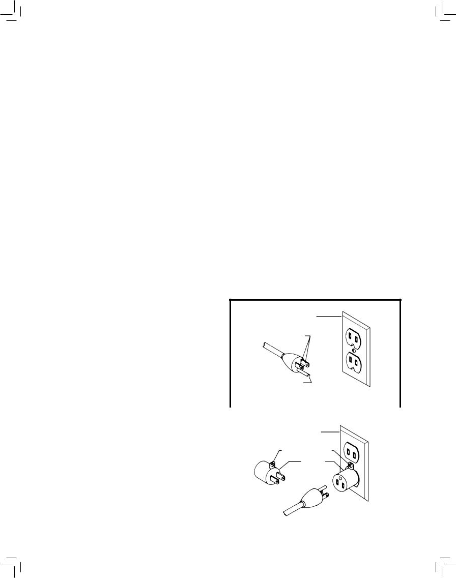
GROUNDING INSTRUCTIONS |
GROUNDED |
|||||||||
OUTLET BOX |
||||||||||
|
SHOCK HAZARD. This machine must be |
CURRENT |
||||||||
|
||||||||||
grounded while in use to protect the operator from electric |
CARRYING |
|||||||||
shock. |
PRONGS |
|||||||||
1. All grounded, cord-connected machines: |
|
|
|
|
|
|
|
|
||
In the event of a malfunction or breakdown, grounding |
|
|
|
|
|
|
|
|
||
provides a path of least resistance for electric current to |
|
|
|
|
|
|
|
|
||
reduce the risk of electric shock. This machine is equipped |
GROUNDING BLADE |
|||||||||
with an electric cord having an equipment-grounding |
||||||||||
IS LONGEST OF THE 3 BLADES |
||||||||||
conductor and a grounding plug. The plug must be plugged |
||||||||||
|
|
|
|
|
|
|
|
|||
into a matching outlet that is properly installed and grounded |
|
|
|
|
|
|
|
|
||
in accordance with all local codes and ordinances. |
|
|
|
Fig. A |
||||||
Do not modify the plug provided - if it will not fit the outlet, |
|
|
|
|
|
|
|
|
||
|
|
|
|
|
|
|
|
|||
have the proper outlet installed by a qualified electrician. |
GROUNDED OUTLET BOX |
|
||||||||
Improper connection of the equipment-grounding conductor |
|
|||||||||
|
|
|
|
|
|
|
|
|||
can result in risk of electric shock. The conductor with |
|
|
GROUNDING |
|
||||||
insulation having an outer surface that is green with or without |
|
|
|
MEANS |
|
|
|
|||
|
|
|
|
|
||||||
yellow stripes is the equipment-grounding conductor. If repair |
|
|
|
|
|
|
|
|
||
|
|
|
ADAPTER |
|
||||||
or replacement of the electric cord or plug is necessary, do |
|
|
|
|
|
|
|
|
||
|
|
|
|
|
|
|
|
|||
not connect the equipment-grounding conductor to a live |
|
|
|
|
|
|
|
|
||
terminal. |
|
|
|
|
|
|
|
|
||
Check with a qualified electrician or service personnel if the |
|
|
|
|
|
|
|
|
||
grounding instruction are not completely understood, or if in |
|
|
|
|
|
|
|
|
||
doubt as to whether the machine is properly grounded. |
|
|
|
|
|
|
|
|
||
Use only 3-wire extension cords that have 3-prong grounding |
|
|
|
|
|
|
|
|
||
type plugs and matching 3-conductor receptacles that accept |
|
|
|
Fig. B |
||||||
the machine’s plug, as shown in Fig. A. |
|
|
|
|||||||
|
|
|
|
|
|
|
|
|||
4

Repair or replace damaged or worn cord immediately.
2.Grounded, cord-connected machines intended for use on a supply circuit having a nominal rating less than 150 volts:
If the machine is intended for use on a circuit that has an outlet that looks like the one illustrated in Fig. A, the machine will have a grounding plug that looks like the plug illustrated in Fig. A. A temporary adapter, which looks like the adapter illustrated in Fig. B may be used to connect this plug to a matching 2-conductor receptacle as shown in Fig. B, if a properly grounded outlet is not available. The temporary adapter should be used only until a properly grounded outlet can be installed by a qualified electrician. The green-colored rigid ear, lug, and the like, extending from the adapter must be connected to a permanent ground such as a properly grounded outlet box. Whenever the adapter is used, it must be held in place with a metal screw.
NOTE: In Canada, the use of a temporary adapter is not permitted by the Canadian Electric Code.
 SHOCK HAZARD. In all cases, make certain that the receptacle in question is properly grounded. If you are not sure, have a qualified electrician check the receptacle.
3. 240 volt single phase operation:
The motor supplied with your machine is a dual voltage, 120/240 volt motor. It is shipped ready-to-run for 120 volt operation. However, it can be converted for 240 volt operation.
A qualified electrician should do the conversion, or the machine can be taken to an Authorized DELTA Service Center. When completed, the machine must conform to the National Electric Code and all local codes and ordinances.
The machine is converted by re-wiring the motor for 240 volts and installing a 240 volt plug on the power supply cord.
Be sure the 240 volt plug is only used in an outlet having the same configuration as the plug illustrated in Fig. C. No adapter should be used with the 240 volt plug.
 SHOCK HAZARD. In all cases, make certain that the receptacle in question is properly grounded. If you are not sure, have a qualified electrician check the receptacle.
EXTENSION CORDS
 Use proper extension cords. Make sure your extension cord is in good condition and is a 3-wire extension cord which has a 3-prong grounding type plug and matching receptacle which will accept the machine’s plug. When using an extension cord, be sure to use one heavy enough to carry the current of the machine. An undersized cord will cause a drop in line voltage, resulting in loss of power and overheating. Fig. D-1 or D-2, shows the correct gauge to use depending on the cord length. If in doubt, use the next heavier gauge. The smaller the gauge number, the heavier the cord.
GROUNDED OUTLET BOX
CURRENT
CARRYING
PRONGS
GROUNDING BLADE IS
LONGEST OF 3 BLADES
Fig. C
MINIMUM GAUGE EXTENSION CORD
RECOMMENDED SIZES FOR USE WITH STATIONARY ELECTRIC MACHINES
|
|
Total |
|
Ampere |
|
Length of |
|
|
Cord in |
Gauge of Extension |
|
|
|
||
Rating |
Volts |
Feet |
Cord |
0-6 |
120 |
up to 25 |
18 AWG |
0-6 |
120 |
25-50 |
16 AWG |
0-6 |
120 |
50-100 |
16 AWG |
0-6 |
120 |
100-150 |
14 AWG |
6-10 |
120 |
up to 25 |
18 AWG |
6-10 |
120 |
25-50 |
16 AWG |
6-10 |
120 |
50-100 |
14 AWG |
6-10 |
120 |
100-150 |
12 AWG |
10-12 |
120 |
up to 25 |
16 AWG |
10-12 |
120 |
25-50 |
16 AWG |
10-12 |
120 |
50-100 |
14 AWG |
10-12 |
120 |
100-150 |
12 AWG |
12-16 |
120 |
up to 25 |
14 AWG |
12-16 |
120 |
25-50 |
12 AWG |
12-16 |
120 |
greater than 50 feet not recommended |
|
Fig. D-1
MINIMUM GAUGE EXTENSION CORD
RECOMMENDED SIZES FOR USE WITH STATIONARY ELECTRIC MACHINES
|
|
Total |
|
Ampere |
|
Length of |
|
|
Cord in |
Gauge of Extension |
|
|
|
||
Rating |
Volts |
Feet |
Cord |
0-6 |
240 |
up to 50 |
18 AWG |
0-6 |
240 |
50-100 |
16 AWG |
0-6 |
240 |
100-200 |
16 AWG |
0-6 |
240 |
200-300 |
14 AWG |
6-10 |
240 |
up to 50 |
18 AWG |
6-10 |
240 |
50-100 |
16 AWG |
6-10 |
240 |
100-200 |
14 AWG |
6-10 |
240 |
200-300 |
12 AWG |
10-12 |
240 |
up to 50 |
16 AWG |
10-12 |
240 |
50-100 |
16 AWG |
10-12 |
240 |
100-200 |
14 AWG |
10-12 |
240 |
200-300 |
12 AWG |
12-16 |
240 |
up to 50 |
14 AWG |
12-16 |
240 |
50-100 |
12 AWG |
12-16 |
240 |
greater than 50 feet not recommended |
|
Fig. D-2
5

FUNCTIONAL DESCRIPTION
FOREWORD
The Delta Industrial Model 50-786 Dust Collector will connect to woodworking machines that accept a 4" (101.6 mm) diameter hose. The 50-786 comes with one 1 micron filter bag and two 6 mil plastic collection bag, and a 4" (101.6 mm) x 5' (152.4 cm) collection hose.
NOTICE: The manual cover illustrates the current production model. All other illustrations contained in the manual are representative only and may not depict the actual labeling or accessories included. These are intended to illustrate technique only.
CARTON CONTENTS
1a |
|
|
|
|
5 |
1b |
|
|
|
14 |
|
|
|
|
|
||
|
|
|
|
4 |
|
|
|
|
|
|
|
|
|
1d |
|
|
|
|
|
|
|
|
|
|
|
6 |
|
|
|
|
|
1c |
|
|
|
|
|
7 |
|
|
|
2 |
|
8 |
|
15 |
|
|
|
|
|
|
|
9
3
10 
11
 13
13
 12
12
1. |
a. Fixed wheels |
3. |
3/8" Lock washers (2) |
|
b. 3/8" x 2-1/2" (63.5 mm) Hex head |
4. |
Retaining nuts (2) |
|
bolts (2) |
5. |
Handle retaining clips (2) |
|
c. 3/8" Lock nuts (2) |
6. |
5/16" x 3/4" (19 mm) Hex head bolts |
|
d. 3/8" Flat washers (4) |
|
(20) |
2. |
Wheel casters (2) |
7. |
5/16" Hex nuts (14) |
|
|
|
17 |
|
16 |
|
|
|
|
|
18 |
|
19 |
|
20 |
|
23 |
|
|
|
21 |
|
|
25
22
24
6
8.5/16" Lock washers (20)
9.#8 x 3/4" (19 mm) Self-tap sheet metal screws (4)
10.Switch Toggle
11.Bracket for bag hanging rod
12.Large OD 5/16" flat washer
13.5/16" x 1" (25.4 mm) hex head bolt
14.Hose clamp (2)
15.Dust intake cap and ring (2)
16.Motor and blower assembly
17.Base
18.Hose
19.Handle
20.Intake adapter
21.Side and front panels (3)
22.Cross panel (2)
23.Lower bag (2)
24.Cloth-covered bag retainer ring
25.Upper bag
UNPACKING AND CLEANING
Carefully unpack the machine and all loose items from the shipping container(s). Remove the rust-preventative oil from unpainted surfaces using a soft cloth moistened with mineral spirits, paint thinner or denatured alcohol.
NOTICE |
Do not use highly volatile solvents such as gasoline, naphtha, acetone or lacquer thinner for cleaning your |
machine.
After cleaning, cover the unpainted surfaces with a good quality household floor paste wax.
ASSEMBLY
 To reduce the risk of injury, turn unit off and disconnect it from power source before installing and removing accessories, before adjusting or when making repairs. An accidental start-up can cause injury
ASSEMBLY TOOLS REQUIRED
Cross head screw driver (not supplied)
12 mm and other open-end or socket wrenches (not supplied)
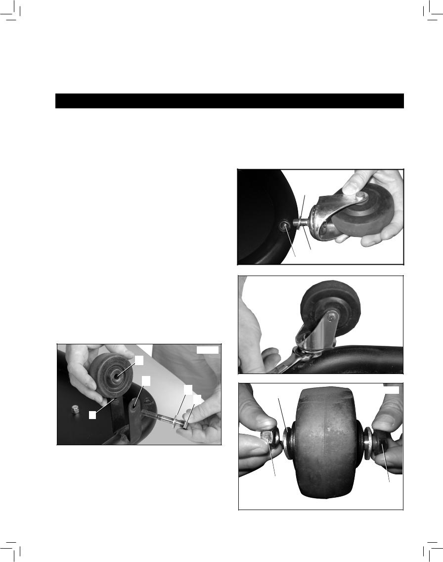
Assembling WHEELS to base
CASTERS (fig. 1, 2)
1.Place 3/8" lockwasher (A) onto stud of caster (C).
2.Insert caster stud into threaded hole in the base
— one shown at (D) — and tighten.
3.Tighten base of caster with wrench or needle-nose pliers, as shown in Figure 2.
4.Repeat for other caster.
FIXED WHEELS (Fig. 3, 4)
1.Place 3/8" flat washer (B) on a 3/8" x 2-1/2" (63.5 mm) hex head bolt (F).
2.Insert hex head bolt through hole (G) in wheel mount bracket, through center hole (H) of wheel and through other hole (I) in wheel mount bracket.
3.Place 3/8" flat washer (B) and 3/8" lock nut (J) onto hex head bolt (F) and tighten.
NOTE: Do not overtighten lock nut (J) onto the bolt
(F). Be sure wheel is still free to rotate.
4.Repeat for other fixed wheel.
FIG. 3
H
G
B
F
ASSEMBLY TIME ESTIMATE
Assembly for this machine takes approximately 1 hour.
A
|
C |
|
FIG. 1 |
||
D |
||
|
FIG. 2
FIG. 4
B
I
j
F
7

Attach side panels to base (Fig. 5–8)
1.Place 5/16" lock washer (K) on 5/16" x 3/4" (19 mm) hex head bolt (L).
2.Line up holes (M) in side panel (N) with holes (O) in base plate.
NOTE: Be sure side panel is oriented as shown in
Figure 6.
3.Place hex head bolt and washer assembly through hole (M) in the side panel and and hole (O) in base.
4.From underneath the base secure side panel to base using a 5/16" hex nut (Q).
5.Repeat for other hole in side panel and base.
6.Repeat above steps for the other side panel. The two panels are shown correctly assembled in Figure 8.
NOTE: FASTEN ALL HARDWARE HAND TIGHT ONLY AT THIS POINT. Hardware will be tightened later in a certain order.
Attach CROSS PANELS TO side panels (fig. 9, 10)
1.Place 5/16" lock washer (K) (inset) on a 5/16" x 3/4"
(19 mm) hex head bolt (L).
2.Line up four holes of cross panel (R) with four lower holes in side panels (N).
3.Insert hex head bolt and washer assembly - (L) and
(K)(inset) - through holes in side panels (N) and then through holes in cross panel (R).
4.Attach cross panel to side panel using 5/16" hex nut
5.Assembled cross panel is shown in Figure 11.
6.Assemble top cross panel in the same manner at holes (SS).
NOTE: FASTEN ALL HARDWARE HAND TIGHT ONLY AT THIS POINT. Hardware will be tightened later in a certain order.
N
R
N
K
L
FIG. 9
N L
K
M M
O
FIG. 5 |
O |
Q
FIG. 6 |
FIG. 7 |
FIG. 8
ss
ss
Q
FIG. 10 |
FIG. 11 |
8

ATTACH FRONT PANEL TO
BASE (fig. 12–15)
1.Place 5/16" lock washer (K) on 5/16" x 3/4" (19 mm) hex head bolt (L).
2.Line up holes in front panel (N) with holes in base plate (S), as shown in Figure 12.
NOTE: Be sure front panel is oriented as shown in Figure 13.
3.Place hex head bolt and washer assembly through holes in front panel (N) and base plate (S).
4.From underneath the base secure front panel to base using a 5/16" hex nut (Q).
5.Repeat for other hole in front panel and base.
6.The front and side panels are shown correctly assembled in Figure 15.
NOTE: FASTEN ALL HARDWARE HAND TIGHT ONLY AT THIS POINT. Hardware will be tightened later in a certain order.
ATTACH MOTOR/BLOWER to STAND (fig. 16, 17)
1.Place motor/blower housing on top of stand. Align holes (T) in the housing with holes (U) in the stand.
2.Place 5/16" lock washer (K) on 5/16" x 3/4" (19 mm) hex head bolt (L).
3.Insert this washer/bolt assembly up through holes
(U)in stand and insert bolt into the threaded holes
(T)of the motor/blower housing. Hand tighten only.
4.Repeat for five remaining holes.
NOTE: FASTEN ALL HARDWARE HAND TIGHT ONLY AT THIS POINT. Hardware will be tightened later in a certain order.
FIG. 15
N
K
 L
L
S
FIG. 12
Q
FIG. 13 |
FIG. 14 |
|
T
FIG. 16 |
U |
|
K
L 
FIG. 17
9
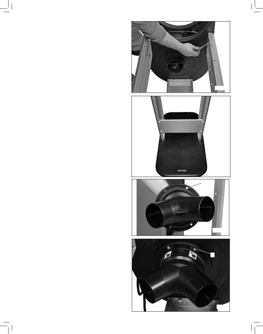
TIGHTEN ALL HARDWARE IN SEQUENCE (FIG. 18, 19)
Using a 12 mm wrench (not included), tighten hardware in this order:
1.Tighten six bolts on motor/blower housing.
2.Tighten all six bolts that attach the side and front panels to the base.
3.Tighten four bolts that attach the cross panel to the side panels.
INSTALL INTAKE ADAPTER (FIG. 20, 21)
Align four holes — one shown at (V) — in intake adapter with the four holes — one shown at (W) — underneath the motor/blower housing. Attach the intake adapter with four #8 self-tapping screws at four holes.
FIG. 18
FIG. 19
V
FIG. 20
 W
W
FIG. 21
10
ATTACHING HANDLE (fIG. 22–26)
1.Attach handle retaining clip (X) into second hole (Y) from the top of the front panel.
2.Orient the clip (X) as shown in inset, with the opening facing away from the dust collector.
3.Repeat for the other retaining clip on the other side of the front panel.
4.Orient the handle as shown in Figure 23.
5.Place ends of handle (Z) through the lower holes on both sides of the front panel, as shown in Figure 23.
6.Clips should hold handle, as shown in Figure 24.
7.Push the non-removable retaining nuts (AA) firmly onto the ends of the handle that stick inside of the front panel.
NOTE: These nuts (AA) are non-removeable. Make sure the handle is properly oriented before installing them.
Y
X
FIG. 22
Z
FIG. 23
FIG. 24
X
AA |
AA |
|
FIG. 25 |
FIG. 26 |
11

ATTACHING THE TOP FILTER
BAG (fig. 27, 28)
1.Place a large 5/16" flatwasher (BB) on a 5/16" x 1"
(25.4 mm) hex head bolt (CC).
2.Position the bracket (DD) on the dust collector.
3.Insert bolt through the hole in the bracket, then thread it into the hole in the dust collector. Tighten securely with a 12 mm wrench.
4.Insert the rod into the pocket (EE) on the filter bag.
6.Insert the rod in the hole in the bracket (FF) (inset).
7.Work the open end of the filter bag into the top groove of the dust collector drum until it is secure and sealed. Bend and fold, as necessary, the internal bag retainer ring to fit it into place.
ATTACHING THE DUST
COLLECTION BAG (fig. 29, 30)
1.Bring the clear plastic dust collection bag up through the middle of the cloth-covered bag retainer ring (GG). Fold about 6" (152.4 mm) of the bag back down around the retainer ring.
2.Place the bag up into in the large hole (HH) in the motor/blower assembly. Fit the retainer ring (GG) into the bottom groove (II). Bend and fold the ring to fit it into place.
3.Tug slightly on the bag to eliminate any slack and to make sure that the bag is secure and will not detach during collection.
BB
CC
DD
FIG. 27
EE 
FF
FF
FIG. 28
FIG. 29
GG
GG
HH
II
FIG. 30
12

ATTACHING THE HOSE TO THE
INTAKE PORT (Fig. 31, 32)
Model 50-786 provides two 4" (101.6 mm) dust ports.
If one intake port is unused, seal this open port using the enclosed dust intake cap.
To install dust intake cap:
Place the open end (JJ) of the intake cap rings around and on the end of one dust intake port before attaching the hose to the other. Cover the open intake port with flat intake cap (KK).
To attach the hose:
Loosely attach the hose clamp (LL) around one end of the flexible hose (MM). Attach the hose to the dust intake port (NN) and tighten the hose clamp (LL).
Use the other hose clamp to attach the other end of the flexible hose to the woodworking machine.
NOTE: Do not operate the dust collector with any dust intake port (NN) uncovered.
JJ
KK
FIG. 31
LL
MM
NN
FIG. 32
OPERATION
OPERATIONAL Controls and ADJUSTMENTS


 For operator safety, make certain the dust intake port is covered with the hose before operating the machine. The rotating fan inside the blower housing is accessible through the dust intake port and is hazardous. Always wear proper apparel. Do not wear jewelry and keep fingers and all foreign objects out of the dust intake port. Always follow the safety rules of this manual.
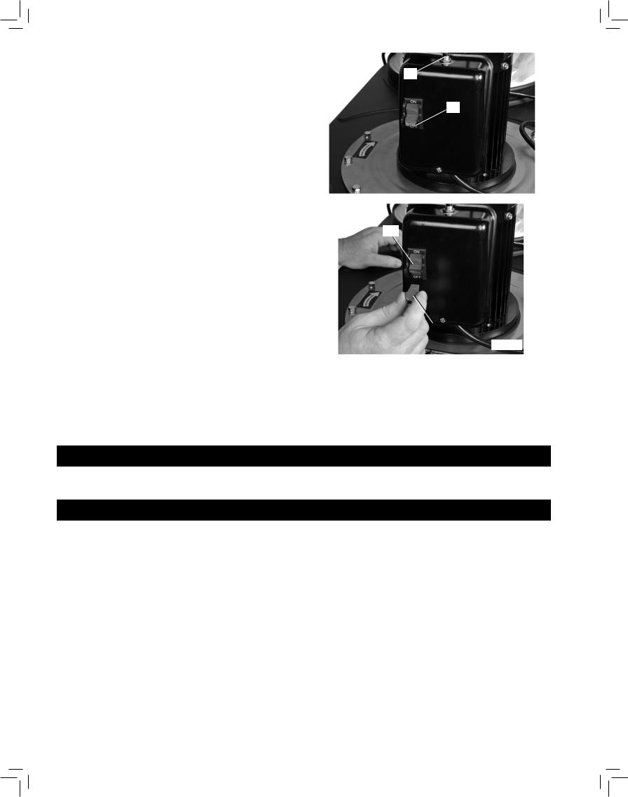
NOTE: The dust collector is shipped with the safety switch toggle (OO) Fig. 33 removed. The toggle must be inserted into the dust collector switch and the switch placed in the "OFF" position before operation.
Remove sticker (PP) covering the switch before inserting toggle (OO) Fig. 34 into switch (QQ).
STARTING AND STOPPING DUST COLLECTOR (fig. 33)


 Make sure that the switch is in the
“OFF” position before plugging cord into outlet. Do not touch the plug’s metal prongs when unplugging or plugging in the cord.
The on/off switch (QQ) is located on the side of the motor. To turn the machine "ON", move the switch up to the "ON" position. To turn the machine "OFF", move the switch down to the "OFF" position.
RR
PP
OO
FIG. 33
OO
FIG. 34
13
LOCKING SWITCH IN |
|
|
|
|
|
|
|
|||
|
|
|
|
|
|
|
||||
"OFF" POSITION (fig. 35, 36) |
|
|
|
RR |
||||||
|
|
|
|
|
|
|
||||
IMPORTANT: When the machine is not in use, the |
|
|
|
|
|
|
|
|||
switch should be locked in the "OFF" position to prevent |
|
|
|
|
|
|
|
|||
unauthorized use. To lock the machine, move the switch |
|
|
|
|
|
OO |
||||
toggle (OO) to the "OFF" position and pull it out of the |
|
|
|
|
|
|
|
|||
switch (QQ) as shown in Figure 36. With the switch toggle |
|
|
|
|
|
|
|
|||
(OO) removed, the switch will not operate. However, |
|
|
|
|
|
|
|
|||
should the switch toggle be removed while the motor is |
|
|
|
|
|
|
|
|||
running, the machine can be turned "OFF," but cannot be |
|
|
|
|
|
|
|
|||
restarted without re-inserting the switch toggle (OO). |
|
|
|
|
|
|
|
|||
|
|
|
|
|
|
|
|
|
|
|
|
|
|
In the event of a power outage (such as |
|
FIG. 35 |
|
|
|
|
|
|
|
|
||||||||
a breaker or fuse trip), always move the switch to the |
|
|
|
|
|
|
|
|||
|
|
|
|
|
|
|
||||
“OFF” position until the main power is restored. |
|
|
|
|
|
|
|
|||
|
|
|
|
|
|
|
||||
|
|
|
FIRE HAZARD. When using this dust |
|
|
|
|
|||
|
|
|
|
|
|
|
||||
|
|
|
|
|
|
|
||||
|
|
|
|
|
|
|
||||
collector, do |
not pick up anything that is burning, |
|
|
|
|
|||||
smoldering, or smoking (matches, cigarettes, or hot |
|
|
|
|
|
|
|
|||
ashes). |
|
|
|
|
|
|
|
|||
|
|
|
EXPLOSION HAZARD. Do not use this |
|
|
|
|
|
|
|
|
|
|
|
|
|
|
|
|
|
|
|
|
|
|
|
|
|
|
|
|
|
|
|
|
|
|
|
|
|
|
|
|
unit to vacuum combustible explosive materials |
|
|
|
|
|
|
|
|||
(coal, grain, or other finely-divided combustible |
|
|
|
|
|
|
|
|||
material). |
|
|
|
|
|
|
|
|||
|
|
|
HEALTH HAZARD. Do not use this |
|
|
|
|
|
|
|
|
|
|
|
|
|
|
|
|
|
|
|
|
|
|
|
|
|
|
|
|
|
|
|
|
|
|
|
|
OO |
|
|
|
unit to vacuum hazardous, toxic, or carcinogenic |
|
|
|
|
|
|
||||
|
|
|
|
|
|
|
||||
|
|
|
|
|
|
|
||||
materials (asbestos, pesticide, or lead-based paint |
|
|
|
|
|
FIG. 36 |
|
|||
debris). |
|
|
|
|
|
|
|
|||
|
|
|
|
|
|
|
||||
CIRCUIT BREAKER
Your dust collector motor is supplied with a resettable circuit breaker. If the motor shuts off or fails to start due to an overload condition, turn the dust collector switch "OFF," let the motor cool three to five minutes, and push the reset button (RR) Fig. 35, on the circuit breaker to reset the breaker. The motor can then be turned on again in the usual manner. If the overload continues to trip, visit our website at www.deltamachinery.com for a list of service centers or call the DELTA Machinery help line at (800) 223-7278 (In Canada call (800) 463-3582).
TROUBLESHOOTING
For assistance with your machine, visit our website at www.deltaportercable.com for a list of service centers or call the
DELTA Machinery help line at (800) 223-7278 (In Canada call 1-800-463-3582).
MAINTENANCE
 To reduce the risk of injury, turn unit off and disconnect it from power source before installing and removing accessories, before adjusting or when making repairs. An accidental start-up can cause injury.
KEEP MACHINE CLEAN
Periodically blow out all air passages with dry compressed air. All plastic parts should be cleaned with a soft damp cloth. NEVER use solvents to clean plastic parts. They could possibly dissolve or otherwise damage the material.
 Wear certified safety equipment for eye, hearing and respiratory protection while using compressed air
FAILURE TO START
Should your machine fail to start, check to make sure the prongs on the cord plug are making good contact in the outlet. Also, check for blown fuses or open circuit breakers in the line.
14

SERVICE
REPLACEMENT PARTS
Use only identical replacement parts. For a parts list or to order parts, visit our website at www. deltaportercableservicenet.com. You can also order parts from your nearest factory-owned branch, Authorized Warranty
Service Center or by calling End User Services at (800) 223-7278 to receive personalized support from one of our highlytrained representatives.
free warning label replacement
If your warning labels become illegible or are missing, call (800) 223-7278 for a free replacement.
TO REDUCE RISK OF INJURY FROM MOVING PARTS: KEEP HANDS AWAY FROM AIR INLET PORTS. ONLY OPERATE WITH INLET PORTS COVERED WITH CAPS OR CONNECTED TO FLEXIBLE HOSE. IMPELLER CONTINUES TO ROTATE AFTER DUST COLLECTOR IS TURNED OFF. MAKE SURE DUST COLLECTOR IS TURNED OFF, DISCONNECTED FROM POWER SOURCE AND THAT IMPELLER HAS STOPPED ROTATING BEFORE SERVICING OR CLEARING DUST AND CHIPS. DO NOT OPERATE WITHOUT HOSE CONNECTED TO INLET PORT AND BAGS OR CANISTER IN PLACE.
REDUCE EL RIESGO DE SUFRIR LESIONES CAUSADAS POR LAS PIEZAS MÓVILES: MANTIENE LAS MANOS ALEJADAS DE LOS ORIFICIOS DE ENTRADA DE AIRE. OPERE ÚNICAMENTE CON LOS ORIFICIOS DE ENTRADA CUBIERTOS CON TAPAS O CONECTADOS A UNA MANGUERA FLEXIBLE. EL IMPULSOR CONTINÚA ROTANDO DESPUÉS DE QUE EL RECOLECTOR DE POLVO ESTÁ APAGADO. ASEGÚRESE DE QUE EL COLECTOR ESTÉ APAGADO, DESCONECTADO DE LA FUENTE DE ALIMENTACIÓN Y DE QUE EL IMPULSOR HAYA PARADO ANTES DE REALIZAR UN MANTENIMIENTO O LIMPIAR EL POLVO Y LAS ASTILLAS. NO OPERE SI LA MANGUERA NO ESTÁ CONECTADA AL ORIFICIO DE ENTRADA O LAS BOLSAS Y LOS DEPÓSITOS NO SE ENCUENTRAN EN SU LUGAR.
POUR RÉDUIRE LE RISQUE DE BLESSURES EN LIEN AVEC DES PIÈCES MOBILES: ÉLOIGNER LES MAINS DES ORIFICES D’ADMISSION DE L’AIR. UTILISER UNIQUEMENT AVEC LES ORIFICES D’ADMISSION RECOUVERTS DE CAPUCHONS OU RACCORDÉS À UN TUYAU FLEXIBLE. L’HÉLICE POURSUIT SON MOUVEMENT MÊME APRÈS L’ARRÊT DU DÉPOUSSIÉREUR. S’ASSURER QUE LE DÉPOUSSIÉREUR EST HORS TENSION, DÉBRANCHÉ ET QUE L’HÉLICE EST IMMOBILE AVANT DE DÉBUTER UNE RÉPARATION OU DE RETIRER LA POUSSIÈRE ET LES COPEAUX DE L’APPAREIL. NE PAS FAIRE FONCTIONNER SI LE TUYAU N’EST PAS CONNECTÉ À L’ORIFICE D’ADMISSION ET SI LES SACS OU L’ABSORBEUR NE SONT PAS EN PLACE.
|
|
|
|
|
|
|
|
|
|
|
|
|
|
|
|
|
|
|
|
|
|
|
|
|
|
|
|
|
|
|
|
|
|
|
|
|
|
|
|
|
|
|
|
|
|
|
|
|
|
|
|
|
|
|
SEVERE LACERATION |
PELIGRO DE LACERACIÓN |
RISQUE DE LACÉRATION GRAVE. NE |
||||||||
HAZARD. DO NOT |
GRAVE. NO OPERE LA |
PAS FAIRE FONCTIONNER L’APPAREIL |
||||||||
OPERATE WITHOUT INTAKE |
UNIDAD SIN EL ADAPTADOR |
SI L’ADAPTATEUR D’ADMISSION |
||||||||
ADAPTER IN PLACE. |
DE ENTRADA EN SU LUGAR. |
N’EST PAS EN PLACE. |
||||||||
|
|
|
|
|
|
|
|
|
|
|
|
|
|
|
|
|
|
|
|
|
|
SEVERE LACERATION HAZARD. UNPLUG PRODUCT AND WAIT 2-1/2 MINUTES TO ALLOW TIME FOR INTERNAL ROTATING COMPONENTS TO STOP PRIOR TO REMOVING DUST CAPS AND HOSES.
PELIGRO DE LACERACIÓN GRAVE. DESENCHUFE EL PRODUCTO Y ESPERE 2-1/2 MINUTOS PARA DAR TIEMPO A QUE LOS
COMPONENTES GIRATORIOS INTERNOS SE DETENGAN ANTES DE RETIRAR TAPAS ANTIPOLVO Y MANGUERAS.
RISQUE DE LACÉRATION GRAVE. DÉBRANCHER LE PRODUIT ET ATTENDRE 2-1/2 MINUTES POUR PERMETTRE AUX COMPOSANTS INTERNES EN ROTATION DE S’ARRÊTER AVANT DE RETIRER LES CAPUCHONS CACHE-POUSSIÈRE ET LES FLEXIBLES.
FALLS CAN CAUSE |
LAS CAÍDAS PUEDEN CAUSAR |
SERIOUS INJURIES. |
LESIONES GRAVES. NO PISAR |
DO NOT STEP OR |
NI PARARSE EN ESTA ÁREA. |
STAND ON THIS AREA. |
|
LES CHUTES PEUVENT CAUSER DE GRAVES BLESSURES. NE MARCHEZ PAS ET NE VOUS TENEZ PAS SUR CET EMPLACEMENT.
|
|
|
|
|
|
|
|
|
|
|
|
|
|
SEE OWNER’S |
CONSULTER LE MODE |
CONSULTE EL MANUAL |
|||||||||
|
MANUAL. |
D’EMPLOI. |
DEL USUARIO. |
|||||||||
|
|
|
|
|
|
|
|
|
|
|
|
|
|
|
|
|
|
|
|
|
|
|
|
|
|
|
|
|
|
|
|
|
|
|
|
|
|
|
|
|
|
|
|
|
|
|
|
|
|
|
|
SEVERE LACERATION HAZARD. UNPLUG PRODUCT AND WAIT 2-1/2 MINUTES TO ALLOW TIME FOR INTERNAL ROTATING COMPONENTS TO STOP PRIOR TO REMOVING DUST CAPS AND HOSES.
TO REDUCE THE RISK OF INJURY USER MUST READ THE INSTRUCTION MANUAL BEFORE OPERATING DUST COLLECTOR. ALWAYS USE PROPER EYE AND RESPIRATORY PROTECTION. SHOCK HAZARD. DO NOT EXPOSE TO RAIN OR USE IN DAMP LOCATIONS. STORE INDOORS. USE ONLY FOR DRY PICK-UP. FIRE/EXPLOSION HAZARD. DO NOT PICK UP OR USE NEAR FLAMMABLE / COMBUSTIBLE LIQUIDS. DO NOT OPERATE WITHOUT HOSE CONNECTED TO INLET PORT AND BAGS OR CANISTER IN PLACE.
COLLECT WOOD MATERIALS ONLY. NEVER USE THE COLLECTOR TO PICK UP METAL SHAVINGS, DUST, OR PARTS.
PELIGRO DE LACERACIÓN GRAVE. DESENCHUFE EL PRODUCTO Y ESPERE 2-1/2 MINUTOS PARA DAR TIEMPO A QUE LOS COMPONENTES GIRATORIOS INTERNOS SE DETENGAN ANTES DE RETIRAR TAPAS ANTIPOLVO Y MANGUERAS.
PARA REDUCIR EL RIESGO DE LESIONES, EL USUARIO DEBE LEER EL MANUAL DE INSTRUCCIONES ANTES DE OPERAR EL RECOLECTOR DE POLVO. SIEMPRE UTILICE PROTECCIÓN ADECUADA PARA LOS OJOS Y VÍAS RESPIRATORIAS. RIESGO DE DESCARGA ELÉCTRICA. NO EXPONGA A LA LLUVIA NI UTILICE EN LUGARES HÚMEDOS. GUARDE BAJO TECHO. SÓLO UTILÍCELO PARA RECOGER RESIDUOS SECOS. NO RECOJA NI UTILICE CERCA DE LÍQUIDOS INFLAMABLES O COMBUSTIBLES. NO OPERE SI LA MANGUERA NO ESTÁ CONECTADA AL ORIFICIO DE ENTRADA O LAS BOLSAS Y LOS DEPÓSITOS NO SE ENCUENTRAN EN SU LUGAR.
RECOJA MATERIALES DE MADERA SOLAMENTE. NUNCA UTILICE EL RECOLECTOR PARA RECOGER RECORTES, POLVO O PIEZAS DE METAL.
RISQUE DE LACÉRATION GRAVE. DÉBRANCHER LE PRODUIT ET ATTENDRE 2-1/2 MINUTES POUR PERMETTRE AUX COMPOSANTS INTERNES EN ROTATION DE S’ARRÊTER AVANT DE RETIRER LES CAPUCHONS CACHE-POUSSIÈRE ET LES FLEXIBLES.
L’UTILISATEUR DOIT LIRE LE MODE D’EMPLOI AVANT D’UTILISER LE DÉPOUSSIÉREUR AFIN DE RÉDUIRE LE RISQUE DE BLESSURE. TOUJOURS UTILISER UNE PROTECTION OCULAIRE ET RESPIRATOIRE ADÉQUATE. RISQUE D’ÉLECTROCUTION. NE PAS EXPOSER L’APPAREIL À LA PLUIE NI L’UTILISER DANS UN ENDROIT HUMIDE. LE RANGER À L’INTÉRIEUR. CONÇU UNIQUEMENT POUR LE RAMASSAGE DE MATIÈRES SÈCHES. NE PAS ASPIRER DE LIQUIDES INFLAMMABLES OU COMBUSTIBLES OU UTILISER LE DÉPOUSSIÉREUR PRÈS DE CEUX-CI. NE PAS FAIRE FONCTIONNER SI LE TUYAU N’EST PAS CONNECTÉ À L’ORIFICE D’ADMISSION ET SI LES SACS OU L’ABSORBEUR NE SONT PAS EN PLACE.
ASPIRER UNIQUEMENT DES MATIÈRES EN BOIS. NE JAMAIS UTILISER LE DÉPOUSSIÉREUR POUR L’ASPIRATION DE COPEAUX, POUSSIÈRES OU MORCEAUX DE MÉTAUX.
SERVICE AND REPAIRS
All quality tools will eventually require servicing and/or replacement of parts. For information about DELTA Machinery, its factory-owned branches, or to locate an Authorized Warranty Service Center, visit our website at www.deltaportercable. com or call our End User Services at (800) 223-7278. All repairs made by our service centers are fully guaranteed against defective material and workmanship. We cannot guarantee repairs made or attempted by others. By calling this number you can also find answers to most frequently asked questions 24 hours/day.
You can also write to us for information at DELTA Machinery, 4825 Highway 45 North, Jackson, Tennessee 38305 - Attention: End User Services. Be sure to include all of the information shown on the nameplate of your tool (model number, type, serial number, date code, etc.)
15

ACCESSORIES
 Since accessories other than those offered by DELTA have not been tested with this product, use of such accessories could be hazardous. To reduce the risk of injury, only DELTA recommended accessories should be used with this product.
A complete line of accessories is available from your DELTA Supplier, DELTA Factory Service Centers, and DELTA
Authorized Service Stations. Please visit our Web Site www.deltaportercable.com for a catalog or for the name of your nearest supplier.
WARRANTY
To register your tool for warranty service visit our website at www.deltaportercable.com.
Five Year Limited New Product Warranty
DELTA will repair or replace, at its expense and at its option, any new DELTA machine, machine part, or machine accessory which in normal use has proven to be defective in workmanship or material, provided that the customer returns the product prepaid to a DELTA factory service center or authorized service station with proof of purchase of the product within five years and provides DELTA with reasonable opportunity to verify the alleged defect by inspection. For all refurbished DELTA product, the warranty period is 180 days. DELTA will not be responsible for any asserted defect which has resulted from normal wear, misuse, abuse or repair or alteration made or specifically authorized by anyone other than an authorized DELTA service facility or representative. Under no circumstances will DELTA be liable for incidental or consequential damages resulting from defective products. Some states do not allow the exclusion or limitation of incidental or consequential damages, so the above limitation or exclusion may not apply to you. This warranty is DELTA’s sole warranty and sets forth the customer’s exclusive remedy, with respect to defective products; all other warranties, express or implied, whether of merchantability, fitness for purpose, or otherwise, are expressly disclaimed by DELTA. For further detail of warranty coverage and warranty repair information, visit www.deltaportercable.com or call (800) 223-7278. This warranty gives you specific legal rights and you may have other rights which vary in certain states or provinces.
LATIN AMERICA: This warranty does not apply to products sold in Latin America. For products sold in Latin America, see country specific warranty information contained in the packaging, call the local company or see website for warranty information.
16
 Loading...