


RTU-EN01
Modbus TCP Remote I/O Communication Module
Operation Manual
DVP-0213920-01

Modbus TCP Remote I/O Communication Module RTU-EN01
Introduction
3 This operation manual only provides introductory information on electrical specification, installation and wiring.
3 RTU-EN01 is an OPEN-TYPE device and therefore should be installed in an enclosure free of airborne dust, humidity, electric shock and vibration. The enclosure should prevent non-maintenance staff from operating the device (e.g. key or specific tools are required to open the enclosure) in case danger and damage on the device may occur. DO NOT touch any terminal when the power is switched on.
3 Please read this manual carefully and follow the instructions to avoid damage on the product or harm on staff.
Table of Content
1 |
INTRODUCTION.................................................................................................................... |
3 |
|
|
1.1 |
Features ...................................................................................................................................... |
3 |
|
1.2 |
Specifications .............................................................................................................................. |
3 |
2 PRODUCT PROFILE & OUTLINE......................................................................................... |
4 |
||
|
2.1 |
Dimension ................................................................................................................................... |
4 |
|
2.2 |
Product Profile............................................................................................................................. |
5 |
|
2.3 |
LED Indicators............................................................................................................................. |
5 |
|
2.4 |
RUN/STOP Switch ...................................................................................................................... |
6 |
|
2.5 |
RJ-45 PIN Definition.................................................................................................................... |
6 |
|
2.6 |
RS-232 PIN Definition ................................................................................................................. |
6 |
|
2.7 |
RS-485 PIN Definition ................................................................................................................. |
6 |
3 |
INSTALLATION & WIRING.................................................................................................... |
6 |
|
|
3.1 |
Connecting RTU-EN01 to DVP Slim Series Digital Input/Output Module.................................... |
6 |
|
3.2 |
Installing RTU-EN01 and DVP Slim Series Digital Input/Output Module onto DIN Rail .............. |
7 |
|
3.3 |
How to Connect RTU-EN01 to Network ...................................................................................... |
7 |
4 WORD DEVICES & BIT DEVICES IN RTU-EN01 ................................................................. |
8 |
||
|
4.1 |
Basic Registers (BR)................................................................................................................... |
8 |
|
4.2 |
Explanations on BR..................................................................................................................... |
9 |
|
4.3 |
External Input Contacts (RX)..................................................................................................... |
12 |
|
4.4 |
External Output Contacts (RY).................................................................................................. |
12 |
|
4.5 |
Control Register for Extension Modules (RCR)......................................................................... |
12 |
|
4.6 |
Word Devices & Bit Devices for Timers (T) ............................................................................... |
13 |
|
4.7 |
Word Devices & Bit Devices for Counters (C)........................................................................... |
14 |
|
4.8 |
Bit Devices for Real-Time Clock (R).......................................................................................... |
14 |
5 |
MODBUS COMMUNICATION ............................................................................................. |
15 |
|
|
5.1 |
Function Codes Supported ....................................................................................................... |
15 |
|
5.2 |
Exception Codes Supported ..................................................................................................... |
15 |
|
5.3 |
Device Type & Device Address ................................................................................................. |
16 |
DVP-PLC Operation Manual |
1 |

Modbus TCP Remote I/O Communication Module RTU-EN01
6 SETTING UP SOFTWARE................................................................................................... |
16 |
|
6.1 |
Setting up Communications & Searching for Communication Modules in DCISoft .................. |
16 |
6.2 |
Recording IP Address............................................................................................................... |
18 |
6.3 |
Basic Settings........................................................................................................................... |
19 |
6.4 |
Network Settings ...................................................................................................................... |
21 |
6.5 |
Setting up Time Server ............................................................................................................. |
22 |
6.6 |
IP Filter ..................................................................................................................................... |
23 |
6.7 |
Smart PLC Setting: IF-THEN.................................................................................................... |
24 |
6.8 |
Smart PLC Setting: Timer......................................................................................................... |
25 |
6.9 |
Smart PLC Setting – Counter ................................................................................................... |
25 |
6.10 |
Smart PLC Setting – RTC......................................................................................................... |
26 |
6.11 |
Analog Input/Output Modules ................................................................................................... |
27 |
6.12 |
I/O Monitoring Table.................................................................................................................. |
29 |
6.13 |
Setting up Gateway .................................................................................................................. |
30 |
6.14 |
Virtual COM ............................................................................................................................. |
33 |
6.15 |
Security Setting ........................................................................................................................ |
35 |
6.16 |
Returning to Default Settings.................................................................................................... |
36 |
6.17 |
Web Function............................................................................................................................ |
36 |
7 APPLICATION EXAMPLES – DCISOFT............................................................................. |
42 |
|
7.15 |
Smart PLC: IF-THEN................................................................................................................ |
42 |
7.16 |
Smart PLC: Timer ..................................................................................................................... |
43 |
7.17 |
Smart PLC: Counter ................................................................................................................. |
44 |
7.18 |
Smart PLC: RTC....................................................................................................................... |
45 |
7.19 |
Virtual COM .............................................................................................................................. |
46 |
Microsoft® and Windows Internet Explorer® are the registered trade mark or trade mark of Microsoft Corporation in the United States and other countries.
Java® is the registered trade mark or trade mark of Sun Microsystems, Inc. in the United States or other countries.
The companies and products mentioned in this operation manual can be the trade mark possesd by the owner of that trade mark right.
2 |
DVP-PLC Operation Manual |

Modbus TCP Remote I/O Communication Module RTU-EN01
1 Introduction
To ensure correct installation and operation of RTU-EN01, please read this manual carefully before using your RTU-EN01. RTU-EN01is an Ethernet remote I/O module for remote setting through Delta’s DCISoft. RTU-EN01 supports maximum 256 digital input/output points. RTU-EN01 supports Modbus TCP protocol and can be used for remote monitoring with graphic control software or human machine interface. RTU-EN01 can also be used as a Modbus TCP gateway, supporting the conversion from Modbus TCP commands to Modbus ASCII/RTU. In addition, in MDI/MDI-X auto-detect, jump wire is not needed when you choose the network cable.
1.1Features
z Supporting smart PLC functions, counter, timer and real-time clock. Able to operate independently without control of PLC main processing unit or programming.
z Able to auto-detect 10/100 Mbps transmission speed; MDI/MDI-X auto-detect.
z Supporting maximum 16 digital input/output modules (Max. 256 I/O points) and 8 analog input/output modules.
z Supporting maximum 16 sets of Modbus TCP connections.
z Supporting Modbus TCP/Modbus gateway (supporting Master mode, connectable to maximum 32 devices). z Parameters can be set up on webpage.
1.2Specifications
Ethernet interface |
|
|
RJ-45 with Auto MDI/MDIX |
Interface |
|
Transmission method |
802.3, 802.3u |
Transmission cable |
Category 5e, 100m (Max) |
Transmission speed |
10/100 Mbps Auto-Detection |
Communication protocol |
ICMP, IP, TCP, UDP, DHCP, NTP, Modbus TCP, HTTP |
|
|
Serial communication interface (COM1)
Interface |
Mini Dim |
Transmission method |
RS-232 |
Communication speed |
19,200 bps |
Communication format |
Stop bit: 1; Parity bit: None; Data bit: 8 |
Communication protocol |
Delta Configuration |
Transmission cable |
DVPACAB215 / DVPACAB230 / DVPACAB2A30 |
|
|
Serial communication interface (COM2)
Interface |
3 PIN feed-through terminal |
|
Transmission method |
RS-485 |
|
Transmission distance |
1,200m |
|
Communication speed |
110, 150, 300, 600, 1,200, 2,400, 4,800, 9,600, 19,200, 38,400, 57,600, 115,200 |
|
bps |
||
|
||
Communication format |
Stop bit: 1, 2; Parity bit: None, Odd, Even; Data bit: 7, 8 |
|
Communication protocol |
Modbus ASCII Modbus RTU |
|
|
|
DVP-PLC Operation Manual |
3 |

Modbus TCP Remote I/O Communication Module RTU-EN01
Environment
|
ESD (IEC 61131-2, IEC 61000-4-2): 8KV Air Discharge |
|
EFT (IEC 61131-2, IEC 61000-4-4): Power Line:±2KV, Digital Input: ±2KV, |
|
Communication I/O: ±2KV |
|
RS (IEC 61131-2, IEC 61000-4-3): 80MHz ~ 100MHz, 10V/m. 1.4GHz ~ 2.0GHz, |
Noise immunity |
10V/m |
|
Conducted Susceptibility Test (EN61000-4-6, IEC61131-2 9.10): 150kHz ~ 80MHz, |
|
3V/m |
|
Surge Test (Biwave IEC61132-2, IEC61000-4-5): Power line 0.5KV DM, Ethernet |
|
0.5KV CM, RS-485 0.5KV CM |
Operation |
0ºC ~ 55ºC (temperature), 50 ~ 95% (humidity), pollution degree 2 |
Storage |
-25ºC ~ 70ºC (temperature), 5 ~ 95% (humidity) |
Shock/vibration |
International standards: IEC61131-2, IEC 68-2-6 (TEST Fc)/IEC61131-2 & IEC |
immunity |
68-2-27 (TEST Ea) |
Certificates |
|
|
|
Electrical specification
Power supply voltage |
24VDC (-15% ~ 20%) (with DC input polarity reverse protection) |
Power fuse capacity |
1.85A/30VDC, Polyswitch |
Power consumption |
2W |
Insulation voltage |
500VDC |
Weight |
116g |
|
|
2 Product Profile & Outline
2.1 Dimension
37.4 60
LAN
POWER
RUN
RUN
BAT.LOW
STOP
RTU-EN01
RS-485
RS-232
Unit: mm
4 |
DVP-PLC Operation Manual |
Modbus TCP Remote I/O Communication Module RTU-EN01
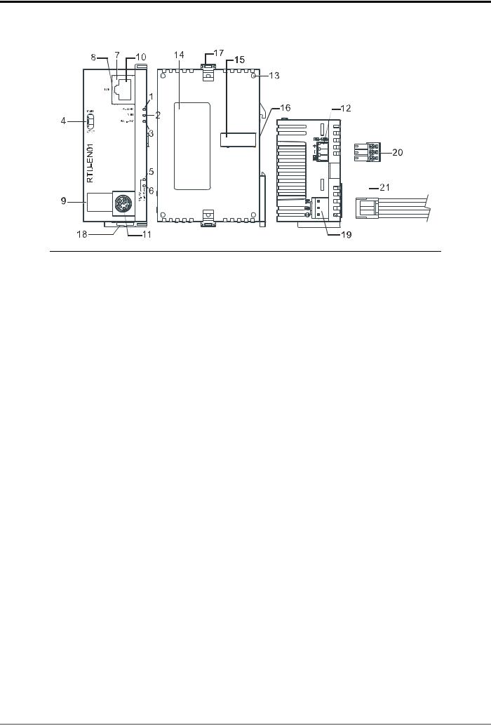
2.2 Product Profile
1. |
POWER indicator |
12. |
RS-485 communication port |
2. |
RUN indicator |
13. |
Extension module positioning hole |
|
|
|
|
3. |
BAT.LOW indicator |
14. |
Nameplate |
|
|
|
|
4. |
RUN/STOP switch |
15. |
Extension port |
|
|
|
|
5. |
RS-232 indicator |
16. |
DIN rail (35mm) |
|
|
|
|
6. |
RS-485 indicator |
17. |
Extension module fixing clip |
|
|
|
|
7. |
LINK/ACK indicator |
18. |
DIN rail clip |
|
|
|
|
8. |
SPEED indicator |
19. |
Power supply port |
|
|
|
|
9. |
Digital display |
20. |
3P terminal block (standard accessory) |
|
|
|
|
10. |
Ethernet communication port |
21. Power supply connection cable (standard |
|
|
|
|
accessory) |
11. |
RS-232 communication port |
|
|
|
|
||
|
|
|
|
2.3 LED Indicators
LED |
Color |
Function |
POWER |
Green |
Power supply indication |
|
|
|
RUN |
Green |
RUN/STOP indication |
|
|
|
BAT.LOW |
Red |
Battery in low power indication |
|
|
|
RS-232 |
Yellow |
Displaying communication status of RS-232 port |
|
|
|
RS-485 |
Yellow |
Displaying communication status of RS-485 port |
|
|
|
LINK/ACT |
Green |
Displaying the status of network |
|
|
|
SPEED |
Yellow |
Displaying the speed of network connection |
|
|
|
DVP-PLC Operation Manual |
5 |
Modbus TCP Remote I/O Communication Module RTU-EN01
2.4 RUN/STOP Switch
|
Status |
|
Explanation |
|
|
1. |
RUN indicator on RTU-EN01 is ON. |
|
RUN |
|
|
|
2. Analog input/output module is in RUN status. |
||
RUN |
|
|
|
|
3. Smart PLC function is running. |
||
|
|
|
|
|
RUN Æ STOP |
1. |
Analog input/output module switches from RUN to STOP status. |
|
|
|
|
|
2. |
Y points on digital input/output module are all OFF. |
|
|
|
||
|
|
|
|
|
|
1. |
RUN indicator on RTU-EN01 is OFF. |
|
STOP |
|
|
STOP |
2. Analog input/output module is in STOP status. |
||
|
|
3. |
Smart PLC function stops. |
|
|
|
|
|
STOP Æ RUN |
1. |
RTU-EN01 re-detects the information on the right-side module. |
|
|
|
|
|
2. |
Analog input/output module switches from STOP to RUN status. |
|
|
|
||
|
|
|
|
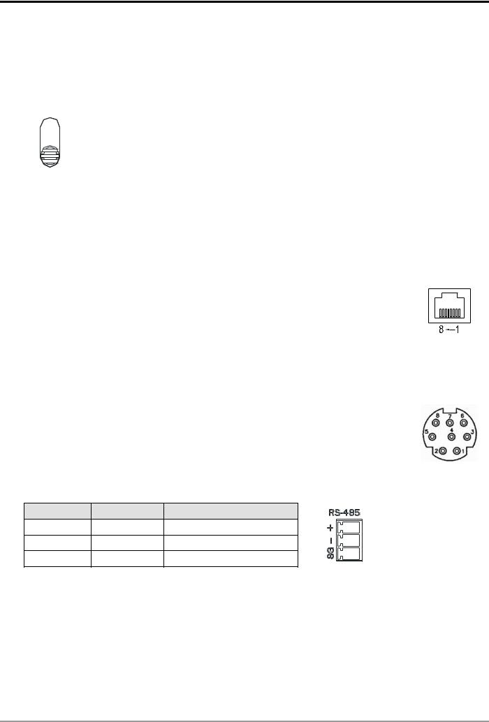
2.5 RJ-45 PIN Definition
PIN |
Signal |
Definition |
|
PIN |
Signal |
Definition |
1 |
Tx+ |
Positive pole for data |
|
5 |
-- |
N/C |
transmission |
|
|||||
|
|
|
|
|
|
|
2 |
Tx- |
Negative pole for data |
|
6 |
Rx- |
Negative pole for data |
transmission |
|
receiving |
||||
|
|
|
|
|
||
3 |
Rx+ |
Positive pole for data |
|
7 |
-- |
N/C |
receiving |
|
|||||
|
|
|
|
|
|
|
4 |
-- |
N/C |
|
8 |
-- |
N/C |
|
|
|
|
|
|
|
2.6 RS-232 PIN Definition
PIN |
Signal |
Definition |
1 |
-- |
N/C |
|
|
|
2 |
-- |
N/C |
|
|
|
3 |
-- |
N/C |
|
|
|
4 |
Rx |
Reception data |
|
|
|
PIN |
Signal |
Definition |
5 |
Tx |
Transmission data |
|
|
|
6 |
-- |
N/C |
|
|
|
7 |
-- |
N/C |
|
|
|
8 |
GND |
Ground |
|
|
|
2.7 RS-485 PIN Definition
PIN |
Signal |
Definition |
|
1 |
SG |
Ground of data |
3 |
2 |
D- |
Negative pole for data |
2 |
|
|||
3 |
D+ |
Positive pole for data |
1 |
|
3 Installation & Wiring
In this section, we will introduce how to connect RTU-EN01 to other devices and the network.
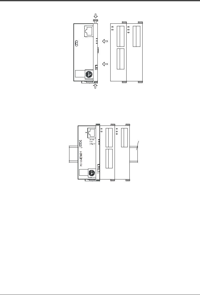
3.1Connecting RTU-EN01 to DVP Slim Series Digital Input/Output Module
z Open the fixing clips on the right top and bottom sides on RTU-EN01. Meet the extension port on RTU-EN01 and the digital input/output module.
z Press and fix the clips on the digital input/output module. Make sure the contact between the modules is fine.
6 |
DVP-PLC Operation Manual |
Modbus TCP Remote I/O Communication Module RTU-EN01
|
LA N |
|
R U N |
P OW ER |
|
R U N |
||
|
||
|
B AT. LO W |
|
S TO P |
|
|
N10 EURT |
|
2-4- 23 58
SR SR
16SP |
02DA |
DVP- |
DVP- |
3.2Installing RTU-EN01 and DVP Slim Series Digital Input/Output Module onto DIN Rail z Use standard 35mm DIN rail.
z Open the DIN rail clips on RTU-EN01 and the digital input/output module and insert the modules onto the rail. z Press the clips to fix the modules onto the rail.
DVP-16SP |
35mm DIN rail
DVP-02DA
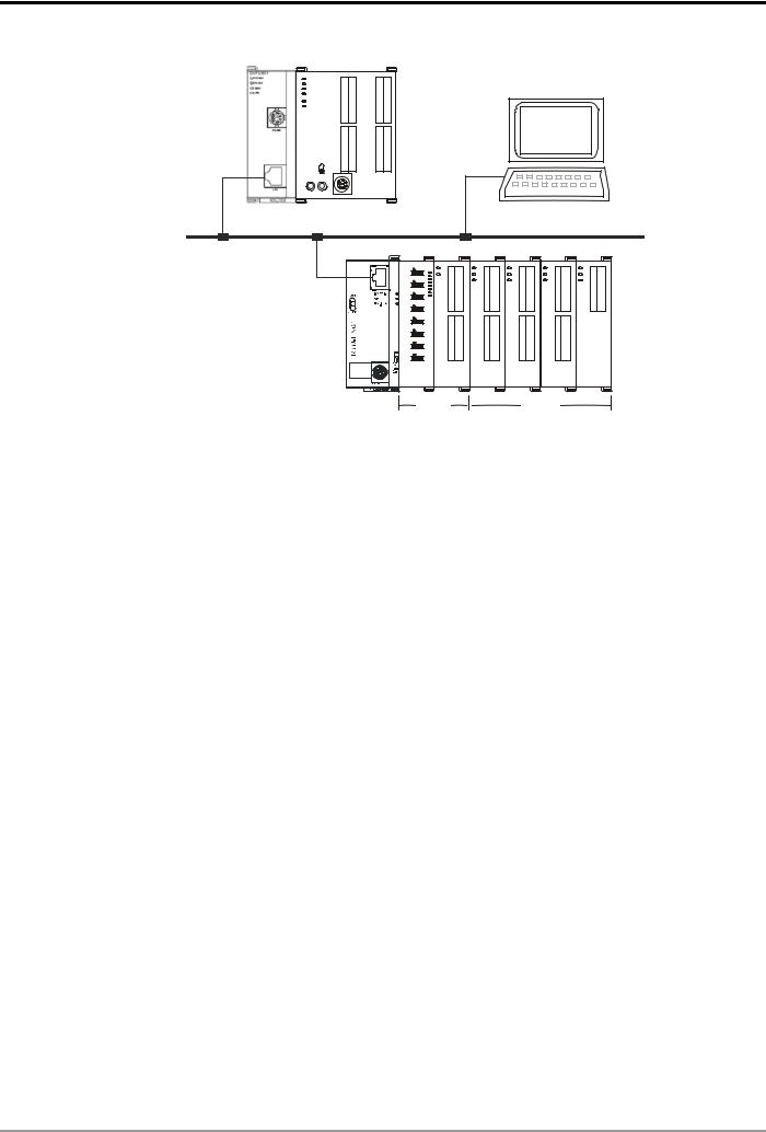
3.3How to Connect RTU-EN01 to Network
Connect RTU-EN01 to the Ethernet hub by CAT-5e twisted pair. Since RTU-EN01 has Auto MDI/MDIX function, CAT-5e twisted pair does not need to jump wire. See below for the connection between the PC and RTU-EN01 modules:
DVP-PLC Operation Manual |
7 |
Modbus TCP Remote I/O Communication Module RTU-EN01
DVPEN01-SL DVP28SV
DVP28SV
RUN
STOP
Ethernet |
|
|
TS8 0 |
16SP |
DA4 0 |
-PV D |
DVP- |
-PV D |
COM2 |
|
|
RTU-EN01 |
DI/DO |
|
PC |
|
|
|
|
|
|
|
|
|
|
|
|
|
|
|
|
|
|
|
|
|
|
|
|
|
|
CT4 0 |
|
|
|
|
|
|
|
TP4 0 |
|
|
|
|
|
|
|
|
02DA |
|
|
|
|||||
-PV D |
|
|
|
|
|
|
|
-PV D |
|
|
|
|
|
|
|
|
DVP- |
|
|
|
|||||
AI/AO
4 |
Word Devices & Bit Devices in RTU-EN01 |
|
|
|||
4.1 |
Basic Registers (BR) |
|
|
|
||
|
|
|
|
|
|
|
|
BR# |
Attribute |
Content |
Explanation |
Default |
Latched |
|
0 |
R |
Model name |
Set up by the system; read only. The model code of |
H’0600 |
YES |
|
RTU-EN01= H’0600. |
|||||
|
|
|
|
|
|
|
|
1 |
R |
Firmware version |
Displaying the current firmware verision in hex, e.g. V1.2 is |
|
YES |
|
indicated as high byte = 0x01 and low byte = 0x20. |
|
||||
|
|
|
|
|
|
|
|
|
|
|
Displaying the data in decimal form. 10,000s digit and 1,000s |
|
|
|
|
|
|
digit are for “month”; 100s digit and 10s digit are for “day”. For |
|
|
|
2 |
R |
Release date of the |
1s digit: 0 = morning; 1 = afternoon. |
|
YES |
|
version |
|
|
|||
|
|
|
Example: 12191 indicates the version released in the afternoon |
|
|
|
|
|
|
|
|
|
|
|
|
|
|
of December 19. |
|
|
|
3 |
R/W |
Start/Stop PLC |
|
|
NO |
|
function |
|
|
|||
|
|
|
|
|
|
|
|
4 |
|
Reserved |
. |
|
NO |
|
|
|
|
|
|
|
|
|
|
COM2 |
RS-485 communication settings. Please refer to the table of |
|
|
|
5 |
R/W |
communication |
H’0368 |
YES |
|
|
baud rate setting and communication format setting. |
|||||
|
|
|
settings |
|
|
|
|
|
|
|
|
|
|
|
6 |
R/W |
Address |
For setting up the station address |
K’1 |
YES |
|
|
|
|
|
|
|
|
7 |
R |
Number of DI points |
Range: 0 ~ 256 |
|
NO |
|
|
|
|
|
|
|
|
8 |
R |
Number of DO points |
Range: 0 ~ 256 |
|
NO |
|
|
|
|
|
|
|
|
9 |
R |
Error code |
Displaying the errors. Please refer to the table of error codes. |
|
NO |
|
|
|
|
|
|
|
|
10 |
|
Reserved |
|
|
NO |
|
|
|
|
|
|
|
|
11 |
R/W |
Communication |
For setting up the communication time-out (ms) in Modbus |
K’5000 |
YES |
|
time-out |
TCP mode. |
||||
|
|
|
|
|
||
|
12 |
R/W |
Communication delay |
For setting up the minimum interval time between every |
K’0 |
YES |
|
time |
communication datum. |
||||
|
|
|
|
|
||
|
13 |
R/W |
TCP connection idle |
For setting up idle time for TCP communication. Unit: second |
K’30 |
YES |
|
time |
|||||
|
|
|
|
|
|
|
|
14 ~ 22 |
|
Reserved |
|
|
NO |
|
|
|
|
|
|
|
|
23 |
R |
Number of analog I/O |
Max. 8 |
|
NO |
|
|
|
modules |
|
|
|
8 |
DVP-PLC Operation Manual |
Modbus TCP Remote I/O Communication Module RTU-EN01
BR# |
Attribute |
Content |
Explanation |
Default |
Latched |
24 |
R |
ID of the 1st analog |
ID of the 1st analog I/O module |
|
NO |
I/O module |
|
||||
|
|
|
|
|
|
25 |
R |
ID of the 2nd analog |
ID of the 2nd analog I/O module |
|
NO |
I/O module |
|
||||
|
|
|
|
|
|
26 |
R |
ID of the 3rd analog |
ID of the 3rd analog I/O module |
|
NO |
I/O module |
|
||||
|
|
|
|
|
|
27 |
R |
ID of the 4th analog |
ID of the 4th analog I/O module |
|
NO |
I/O module |
|
||||
|
|
|
|
|
|
28 |
R |
ID of the 5th analog |
ID of the 5th analog I/O module |
|
NO |
I/O module |
|
||||
|
|
|
|
|
|
29 |
R |
ID of the 6th analog |
ID of the 6th analog I/O module |
|
NO |
I/O module |
|
||||
|
|
|
|
|
|
30 |
R |
ID of the 7th analog |
ID of the 7th analog I/O module |
|
NO |
I/O module |
|
||||
|
|
|
|
|
|
31 |
R |
ID of the 8th analog |
ID of the 8th analog I/O module |
|
NO |
I/O module |
|
||||
|
|
|
|
|
|
32 ~ 49 |
|
Reserved |
|
|
NO |
|
|
|
|
|
|
50 |
R/W |
RTC settings |
Settings of the real-time clock |
|
NO |
|
|
|
|
|
|
51 |
R/W |
Year |
Range: 1970 ~ 2099 |
|
YES |
|
|
|
|
|
|
52 |
R/W |
Week |
Range: 1 ~ 7 |
|
YES |
|
|
|
|
|
|
53 |
R/W |
Month |
Range: 1 ~ 12 |
|
YES |
|
|
|
|
|
|
54 |
R/W |
Day |
Range: 1 ~ 31 |
|
YES |
|
|
|
|
|
|
55 |
R/W |
Hour |
Range: 0 ~ 23 |
|
YES |
|
|
|
|
|
|
56 |
R/W |
Minute |
Range: 0 ~ 59 |
|
YES |
|
|
|
|
|
|
57 |
R/W |
Second |
Range: 0 ~ 59 |
|
YES |
|
|
|
|
|
|
58 ~ 59 |
|
Reserved |
|
|
NO |
|
|
|
|
|
|
60 |
|
Reserved |
|
|
NO |
|
|
|
|
|
|
61 ~ 63 |
|
Reserved |
|
0 |
NO |
|
|
|
|
|
|
Symbol “R” refers to ready only; “R/W” refers to read and write.
4.2 Explanations on BR
BR#0: Model Name
Explanations:
1.Model code of RTU-EN01 = H’0600.
2.You can read the model code in the program to see if the extension module exists.
BR#1: Firmware Version
Explanations:
The firmware version of RTU-EN01 is displayed in hex, e.g. H’0100 indicates version V1.00
BR#2: Release Date of the Version
Explanations:
Displaying the data in decimal form. 10,000s digit and 1,000s digit are for “month”; 100s digit and 10s digit are for “day”. For 1s digit: 0 = morning; 1 = afternoon.
Example: 12191 indicates the version released in the afternoon of December 19.
DVP-PLC Operation Manual |
9 |

Modbus TCP Remote I/O Communication Module RTU-EN01
BR#5: COM2 Communication Settings
Explanations:
b0 ~ b3
|
Interface |
|
|
Explanation |
|
|
||
|
|
|
|
|
|
|
|
|
|
|
Data |
Baud rate |
Data |
Baud rate |
Data |
Baud rate |
|
|
|
(bps) |
(bps) |
(bps) |
||||
|
|
|
|
|
||||
|
|
|
|
|
|
|
|
|
Content |
COM2 |
0x1 |
110 |
0x6 |
2,400 |
0xB |
57,600 |
|
|
|
|
|
|
|
|||
0x2 |
150 |
0x7 |
4,800 |
0xC |
115,200 |
|||
|
RS-485 |
|||||||
|
|
|
|
|
|
|
||
|
0x3 |
300 |
0x8 |
9,600 |
|
|
||
|
|
|
|
|||||
|
|
|
|
|
|
|
|
|
|
|
0x4 |
600 |
0x9 |
19,200 |
|
|
|
|
|
|
|
|
|
|
|
|
|
|
0x5 |
1,200 |
0xA |
38,400 |
|
|
|
|
|
|
|
|
|
|
|
|
b4 ~ b7
|
|
|
|
b7 |
|
|
|
|
b6 ~ b5 |
|
|
|
b4 |
|
||
|
|
|
Stop bit |
|
|
|
Parity bit |
|
|
|
Data bit |
|
|
|||
|
|
|
|
|
|
00 : None parity bit |
|
|
|
|||||||
|
Explanation |
|
0: 1 Stop bit |
|
|
|
|
0 : 7 Data bits |
|
|||||||
|
|
|
|
|
01 : Odd parity bit |
|
|
|||||||||
|
|
|
1: 2 Stop bits |
|
|
|
1 : 8 Data bits |
|
||||||||
|
|
|
|
|
11 : Even parity bit |
|
|
|||||||||
|
|
|
|
|
|
|
|
|
|
|
|
|||||
|
|
|
|
|
|
|
|
|
|
|
|
|
|
|
||
|
|
0000 (0) |
7-N-1 |
0011 (3) |
|
8-O-1 |
1000 (8) |
|
7-N-2 |
|
1011 (B) |
8-O-2 |
||||
|
Content |
|
|
|
|
|
|
|
|
|
|
|
||||
|
0001 (1) |
8-N-1 |
0110 (6) |
|
7-E-1 |
1001 (9) |
|
8-N-2 |
|
1110 (E) |
7-E-2 |
|||||
|
|
|
|
|
|
|
|
|
|
|
|
|
||||
|
|
0010 (2) |
7-O-1 |
0111 (7) |
|
8-E-1 |
1010 (A) |
|
7-O-2 |
|
1111 (F) |
8-E-2 |
||||
|
|
|
|
|
|
|
|
|
|
|
|
|
|
|
|
|
|
|
|
|
|
|
|
|
b8 ~ b15 |
|
|
|
|
|
|
|
|
|
Content |
|
|
|
|
|
|
|
Explanation |
|
|
|
|
|
||
|
0x02 |
|
|
|
|
|
|
|
Modbus RTU Master |
|
|
|
|
|
||
|
|
|
|
|
|
|
|
|
|
|
|
|
|
|||
|
0x03 |
|
|
|
|
|
|
Modbus ASCII Master |
|
|
|
|
|
|||
|
|
|
|
|
|
|
|
|
|
|
|
|
|
|
|
|
BR#6: Address
Explanations
For filling in or reading the Modbus address. The address will be displayed in the message display after being set up. Range: 1 ~ 247.
BR#7: Number of DI Points
Explanations
Read the number of digital input points from BR#7. Range: 0 ~ 256. Max. I/O points: 256.
BR#8: Number of DO Points
Explanations
Read the number of digital output points from BR#8. Range: 0 ~ 256. Max. I/O points: 256.
BR#9: Error Code
Explanations:
Error code = 0 refers to no error occurring.
Code |
Indication |
How to correct |
|
|
|
10 |
DVP-PLC Operation Manual |

Modbus TCP Remote I/O Communication Module RTU-EN01
Code |
Indication |
|
How to correct |
|
F0 |
Returning to default setting |
-- |
|
|
|
|
|
|
|
F1 |
RTU-EN01 being powered |
-- |
|
|
|
|
|
||
F2 |
Power supply in low voltage |
Check if the power supply of the module works normally. |
||
|
|
|
|
|
|
|
1. |
Check if the settings of smart PLC are incorrect. |
|
F3 |
Internal error. Manufacturing error. |
2. |
Re-power RTU-EN01. If the error still exists, try step 3. |
|
3. Reset RTU-EN01. If the error still exists, send the module back to |
||||
|
|
|||
|
|
|
the manufacturer for repair. |
|
|
|
|
||
F5 |
Network connection error |
Check if RTU-EN01 is connected normally to the network. |
||
|
|
|
||
F6 |
Insufficient TCP connection |
Check if the number of connected modules exceeds the maximum. |
||
|
|
|
||
F7 |
RS-485 setting error |
Check if the RS-485 communication format is correct. |
||
|
|
|
|
|
|
|
1. |
DHCP request failure. |
|
|
|
2. |
IP setting error. |
|
F8 |
IP setting error |
3. |
MASK setting error. |
|
|
|
4. |
Gateway does not exist in the same subnet. |
|
|
|
5. |
Returning to default setting. |
|
|
|
|
||
|
|
Check if the configuration of the right-side module has been modified. If |
||
F9 |
Right-side module error |
the error still exists, check if the number of I/O points exceeds the |
||
maximum and whether the there are more than 8 analog I/O modules |
||||
|
|
|||
|
|
connected. |
||
|
|
|
|
|
04 |
Slave error |
1. |
Check if RTU-EN01 and RS-485 is connected normally. |
|
|
|
2. Check if the series transmission speed is consistent with that of other |
||
0b |
No response from station |
|||
|
nodes on the network. |
|||
|
|
|
|
|
BR#11: Communication Time-out (ms)
Explanations:
For setting up the communication time-out. Default = 5,000ms. For example, if you wish to set up the communication time-out to 7 seconds manually, write 7000 to BR#11. Range: 5 ~ 65,535.
BR#12: Communication Delay Time (ms)
Explanations:
For setting up the minimum interval time between every Modbus command. Default = 0ms. For example, if you wish to set up the communication delay time to 100ms manually, write 100 into BR#12. Range: 0 ~ 65,535.
BR#13: TCP Connection Idle Time (s)
Explanations:
For setting up the TCP connection idle time. Default = 30 seconds. For example, if you wish to set up the idle time to 7 seconds manually, write 7 into BR#13. Range: 5 ~ 65,535.
BR#23: Number of Analog I/O Modules
Explanations:
Read the number of right-side modules from BR#23. Max. 8.
BR#24 ~ #31: ID of the 1s t ~ 8t h Analog I/O Module
Explanations:
Read the ID of the 1st ~ 8th analog I/O modules from BR#24 ~ BR#31.
DVP-PLC Operation Manual |
11 |

Modbus TCP Remote I/O Communication Module RTU-EN01
BR#50 ~ BR#57: RTC Settings
Explanations:
For setting up the real-time clock (RTC). When BR#9 = 1, RTU-EN01 will stop to update the RTC values to BR#10 ~ #16. Once the setup is completed, RTU-EN01 will set BR#9 to 0.
Allowed range for RTC: 1970/01/01 00:00:00 ~ 2037/12/31 23:59:59
BR#9 |
|
|
|
0 |
No action |
|
|
1 |
RTC stops |
|
|
2 |
RTC being set |
|
|
4.3 External Input Contacts (RX)
RX# |
Attribute |
Content |
Explanation |
Default |
Latched |
0 ~ 255 |
R/W |
External input contact |
Input points on analog I/O module |
OFF |
NO |
|
|
|
|
|
|
Symbol “R” refers to ready only; “R/W” refers to read and write.
RX#0 ~ #255: External Input Contact
Explanations:
The right-side extension interface on RTU-EN01 is able to connect to DVP-Slim series digital I/O modules. RTU-EN01 supports maximum 256 I/O points.
4.4 External Output Contacts (RY)
RY# |
Attribute |
Content |
Explanation |
Default |
Latched |
0 ~ 255 |
R/W |
External output contact |
Output points on analog I/O module |
OFF |
NO |
|
|
|
|
|
|
Symbol “R” refers to ready only; “R/W” refers to read and write.
RY#0 ~ #255: External Output Contact
Explanations:
The right-side extension interface on RTU-EN01 is able to connect to DVP-Slim series digital I/O modules. RTU-EN01 supports maximum 256 I/O points.
4.5 Control Register for Extension Modules (RCR)
RCR# |
Attribute |
|
Content |
Explanation |
Default |
Latched |
|
0 ~ 49 |
R/W |
The 1st |
analog I/O |
Control register for the 1st analog I/O |
-- |
NO |
|
module |
|
module |
|||||
|
|
|
|
|
|
||
50 |
~ 99 |
R/W |
The 2nd analog I/O |
Control register for the 2nd analog I/O |
-- |
NO |
|
module |
|
module |
|||||
|
|
|
|
|
|
||
100 |
~ 149 |
R/W |
The 3rd |
analog I/O |
Control register for the 3rd analog I/O |
-- |
NO |
module |
|
module |
|||||
|
|
|
|
|
|
||
150 |
~ 199 |
R/W |
The 4th |
analog I/O |
Control register for the 4th analog I/O |
-- |
NO |
module |
|
module |
|||||
|
|
|
|
|
|
||
12 |
DVP-PLC Operation Manual |

Modbus TCP Remote I/O Communication Module RTU-EN01
RCR# |
Attribute |
|
Content |
Explanation |
Default |
Latched |
200 ~ 249 |
R/W |
The 5th |
analog I/O |
Control register for the 5th analog I/O |
-- |
NO |
module |
|
module |
||||
|
|
|
|
|
||
250 ~ 299 |
R/W |
The 6th |
analog I/O |
Control register for the 6th analog I/O |
-- |
NO |
module |
|
module |
||||
|
|
|
|
|
||
300 ~ 349 |
R/W |
The 7th |
analog I/O |
Control register for the 7th analog I/O |
-- |
NO |
module |
|
module |
||||
|
|
|
|
|
||
350 ~ 399 |
R/W |
The 8th |
analog I/O |
Control register for the 8th analog I/O |
-- |
NO |
module |
|
module |
||||
|
|
|
|
|
Symbol “R” refers to ready only; “R/W” refers to read and write.
RCR#0 ~ #399: Control Register for Right-Side Analog I/O Modules
Explanations:
By reading/writing RCR in RTU-EN01, you are able to store or retrieve the data in the control register (CR) inside the analog input/output module.
Example: RCR#0 corresponds to CR#0 in the 1st analog I/O module. RCR#260 corresponds to CR#10 in the 6th analog I/O module. Extension module closest to RTU-EN01 is regarded the 1st module.
4.6 Word Devices & Bit Devices for Timers (T)
T# |
Attribute |
Register/coil name |
Explanation |
Default |
|
Latched |
0 |
R/W |
Timer 0 |
Timer |
0/OFF |
|
NO |
|
|
|
|
|
|
|
1 |
R/W |
Timer 1 |
Timer |
0/OFF |
|
NO |
|
|
|
|
|
|
|
2 |
R/W |
Timer 2 |
Timer |
0/OFF |
|
NO |
|
|
|
|
|
|
|
3 |
R/W |
Timer 3 |
Timer |
0/OFF |
|
NO |
|
|
|
|
|
|
|
4 |
R/W |
Timer 4 |
Timer |
0/OFF |
|
NO |
|
|
|
|
|
|
|
5 |
R/W |
Timer 5 |
Timer |
0/OFF |
|
NO |
|
|
|
|
|
|
|
6 |
R/W |
Timer 6 |
Timer |
0/OFF |
|
NO |
|
|
|
|
|
|
|
7 |
R/W |
Timer 7 |
Timer |
0/OFF |
|
NO |
|
|
|
|
|
|
|
8 |
R/W |
Timer 8 |
Timer |
0/OFF |
|
NO |
|
|
|
|
|
|
|
9 |
R/W |
Timer 9 |
Timer |
0/OFF |
|
NO |
|
|
|
|
|
|
|
10 |
R/W |
Timer 10 |
Timer |
0/OFF |
|
NO |
|
|
|
|
|
|
|
11 |
R/W |
Timer 11 |
Timer |
0/OFF |
|
NO |
|
|
|
|
|
|
|
12 |
R/W |
Timer 12 |
Timer |
0/OFF |
|
NO |
|
|
|
|
|
|
|
13 |
R/W |
Timer 13 |
Timer |
0/OFF |
|
NO |
|
|
|
|
|
|
|
14 |
R/W |
Timer 14 |
Timer |
0/OFF |
|
NO |
|
|
|
|
|
|
|
15 |
R/W |
Timer 15 |
Timer |
0/OFF |
|
NO |
|
|
|
|
|
|
|
Symbol “R” refers to ready only; “R/W” refers to read and write.
T#0: Timer 0
Explanations:
When the timer is enabled, it will start to time according to the settings. When the timing reaches the target, the bit device T0 will be ON. When the bit device is reset, the word device will be reset to 0 as well.
DVP-PLC Operation Manual |
13 |

Modbus TCP Remote I/O Communication Module RTU-EN01
T#1 ~ #15: Timer 1 ~ 15
Explanations:
Please refer to T#0.
4.7 Word Devices & Bit Devices for Counters (C)
C# |
Attribute |
Register/coil name |
Explanation |
Default |
Latched |
0 |
R/W |
Counter 0 |
Counting up/down counter |
0/OFF |
NO |
|
|
|
|
|
|
1 |
R/W |
Counter 1 |
Counting up/down counter |
0/OFF |
NO |
|
|
|
|
|
|
2 |
R/W |
Counter 2 |
Counting up/down counter |
0/OFF |
NO |
|
|
|
|
|
|
3 |
R/W |
Counter 3 |
Counting up/down counter |
0/OFF |
NO |
|
|
|
|
|
|
4 |
R/W |
Counter 4 |
Counting up/down counter |
0/OFF |
NO |
|
|
|
|
|
|
5 |
R/W |
Counter 5 |
Counting up/down counter |
0/OFF |
NO |
|
|
|
|
|
|
6 |
R/W |
Counter 6 |
Counting up/down counter |
0/OFF |
NO |
|
|
|
|
|
|
7 |
R/W |
Counter 7 |
Counting up/down counter |
0/OFF |
NO |
|
|
|
|
|
|
8 |
R/W |
Counter 8 |
Counting up/down counter |
0/OFF |
NO |
|
|
|
|
|
|
9 |
R/W |
Counter 9 |
Counting up/down counter |
0/OFF |
NO |
|
|
|
|
|
|
10 |
R/W |
Counter 10 |
Counting up/down counter |
0/OFF |
NO |
|
|
|
|
|
|
11 |
R/W |
Counter 11 |
Counting up/down counter |
0/OFF |
NO |
|
|
|
|
|
|
12 |
R/W |
Counter 12 |
Counting up/down counter |
0/OFF |
NO |
|
|
|
|
|
|
13 |
R/W |
Counter 13 |
Counting up/down counter |
0/OFF |
NO |
|
|
|
|
|
|
14 |
R/W |
Counter 14 |
Counting up/down counter |
0/OFF |
NO |
|
|
|
|
|
|
15 |
R/W |
Counter 15 |
Counting up/down counter |
0/OFF |
NO |
|
|
|
|
|
|
Symbol “R” refers to ready only; “R/W” refers to read and write.
C#0: Counter 0
Explanations:
When the counter is enabled and RX turns from OFF to ON, counting up or counting down will be set according to the settings. When the counting reaches the target, the counting will stop, and the bit device C0 will be set to ON. When the bit device is reset, the word device will be reset to 0 as well.
C#1 ~ #15: Counter 1 ~ 15
Explanations:
Please refer to C#0.
4.8Bit Devices for Real-Time Clock (R)
R# |
Attribute |
Content |
Explanation |
Default |
Latched |
0 |
R/W |
RTC 0 |
Real-time clock |
OFF |
NO |
|
|
|
|
|
|
1 |
R/W |
RTC 1 |
Real-time clock |
OFF |
NO |
|
|
|
|
|
|
2 |
R/W |
RTC 2 |
Real-time clock |
OFF |
NO |
|
|
|
|
|
|
3 |
R/W |
RTC 3 |
Real-time clock |
OFF |
NO |
|
|
|
|
|
|
4 |
R/W |
RTC 4 |
Real-time clock |
OFF |
NO |
|
|
|
|
|
|
5 |
R/W |
RTC 5 |
Real-time clock |
OFF |
NO |
|
|
|
|
|
|
14 |
DVP-PLC Operation Manual |
 Loading...