


 Loading...

Preface
Thank you very much for purchasing DELTA’s AC servo products.
This manual will be helpful in the installation, wiring, inspection, and operation of Delta AC servo drive and motor. Before using the product, please read this user manual to ensure correct use.
You should thoroughly understand all safety precautions (DANGERS, WARNINGS and STOPS) before proceeding with the installation, wiring and operation. If you do not understand please contact your local Delta sales representative. Place this user manual in a safe location for future reference.
Using This Manual
Contents of this manual
This manual is a user guide that provides the information on how to install, operate and maintain ASDA-AB series AC servo drives and ECMA series AC servo motors. The contents of this manual include the following topics:
z Installation of AC servo drives and motors z Configuration and wiring
z Trial run steps
z Control functions and adjusting methods of AC servo drives z Parameter settings
z Communication protocol
zInspection and maintenance
zTroubleshooting
zApplication examples
Who should use this manual
This manual is intended for the following users:
zThose who are responsible for designing
zThose who are responsible for installing or wiring
zThose who are responsible for operating or programming
zThose who are responsible for maintaining or troubleshooting
Important precautions
Before using the product, please read this user manual thoroughly to ensure correct use. Store this manual in a safe and handy place for quick reference whenever necessary. Always observe the following precautions:
zDo not use the product in a potentially explosive environment.
zInstall the product in a clean and dry location free from corrosive and inflammable gases or liquids.
zDo not connect commercial power to the U, V, W terminals. Failure to observe this precaution will cause severe damage to the Servo drive.
Revision January 2009 |
i |
Preface|ASDA-AB Series
zEnsure that the motor and drive are correctly connected to a ground. The grounding method must comply with the electrical standard of the country (Please refer to NFPA 70: National Electrical Code, 2005 Ed.).
zDo not disconnect the AC servo drive and motor while the power is ON.
zDo not attach, modify or remove wiring while power is applied to the AC servo drive.
zBefore starting the operation with a mechanical system connected, make sure the emergency stop equipment can be energized and work at any time.
zDo not touch the drive heat sink or the servo motor during operation, this may cause serious personnel injury.
PLEASE READ PRIOR TO INSTALLATION FOR SAFETY.
Carefully note and observe the following safety precautions when receiving, inspecting, installing, operating, maintaining and troubleshooting. The following words, DANGER, WARNING and STOP are used to mark safety precautions when using the Delta’s servo product. Failure to observe these precautions may void the warranty!
ASDA-AB series drives are open type servo drives and must be installed in an NEMA enclosure such as a protection control panel during operation to comply with the requirements of the international safety standards. They are provided with precise feedback control and high-speed calculation function incorporating DSP (Digital Signal Processor) technology, and intended to drive three-phase permanent magnet synchronous motors (PMSM) to achieve precise positioning by means of accurate current output generated by IGBT (Insulated Gate Bipolar Transistor).
ASDA-AB series drives can be used in industrial applications and for installation in an end-use enclosure that do not exceed the specifications defined in the ASDA-AB series user manual (Drives, cables and motors are for use in a suitable enclosure with a minimum of a UL50 type 1 or NEMA 250 Type 1 rating).
The words, DANGER, WARNING and STOP, have the following meaning:
Indicates a potentially hazardous situation and if not avoided, may result in serious injury or death.
Indicates a potentially hazardous situation and if not avoided, may result in minor to moderate injury or serious damage to the product.
Indicates an improper action that it is not recommended. Doing so may cause damage or malfunction.
Unpacking Check
¾Please ensure that both the servo drive and motor are correctly matched for size (power rating). Failure to observe this precaution may cause fire, seriously damage to the drive / motor or cause personal injury.
Installation
¾Do not install the product in a location that is outside the stated specification for the drive and motor. Failure to observe this caution may result in electric shock, fire, or personal injury.
ii |
Revision January 2009 |
Preface|ASDA-AB Series
Wiring
¾ Connect the ground terminals to a class-3 ground (Ground resistance should not exceed 100 Ω). Improper grounding may result in electric shock or fire.
¾Do not connect any power supplies to the U, V, W terminals. Failure to observe this precaution may result in serious injury, damage to the drive or fire.
¾Ensure that all screws, connectors and wire terminations are secure on the power supply, servo drive and motor. Failure to observe this caution may result in damage, fire or personal injury.
Operation
¾ Before starting the operation with a mechanical system connected, change the drive parameters to match the user-defined parameters of the mechanical system. Starting the operation without matching the correct parameters may result in servo drive or motor damage, or damage to the mechanical system.
¾Ensure that the emergency stop equipment or device is connected and working correctly before operating the motor that is connected to a mechanical system.
¾Do not approach or touch any rotating parts (e.g. shaft) while the motor is running. Failure to observe this precaution may
cause serious personal injury.
¾ In order to prevent accidents, the initial trial run for servo motor should be conducted under no load conditions (separate the motor from its couplings and belts).
¾For the initial trial run, do not operate the servo motor while it is connected to its mechanical system. Connecting the motor to its mechanical system may cause damage or result in personal injury during the trail run. Connect the servo motor once it has successfully completed a trail run.
¾Caution: Please perform trial run without load first and then perform trial run with load connected. After the servo motor is running normally and regularly without load, then run servo motor with load connected. Ensure to perform trial run in this order to prevent unnecessary danger.
¾Do not touch either the drive heat sink or the motor during operation as they may become hot and personal injury may result.
Maintenance and Inspection
¾Do not touch any internal or exposed parts of servo drive and servo motor as electrical shock may result.
¾Do not remove the operation panel while the drive is connected to an electrical power source otherwise electrical shock may result.
¾Wait at least 10 minutes after power has been removed before touching any drive or motor terminals or performing any wiring and/or inspection as an electrical charge may still remain in the servo drive and servo motor with hazardous voltages even after power has been removed.
¾Do not disassemble the servo drive or motor as electric shock may result.
¾Do not connect or disconnect wires or connectors while power is applied to the drive and motor.
¾Only qualified personnel who have electrical knowledge should conduct maintenance and inspection.
Main Circuit Wiring
¾ Install the encoder cables in a separate conduit from the motor power cables to avoid signal noise. Separate the conduits by 30cm (11.8inches) or more.
¾Use multi-stranded twisted-pair wires or multi-core shielded-pair wires for signal, encoder (PG) feedback cables. The maximum length of command input cable is 3m (9.84ft.) and the maximum length of encoder (PG) feedback cables is 20m (65.62ft.).
¾As a charge may still remain in the drive with hazardous voltages even after power has been removed, be sure to wait at least 10 minutes after power has been removed before performing any wiring and/or inspection.
¾It is not recommended to frequently power the drive on and off. Do not turn the drive off and on more than once per minute as
high charging currents within the internal capacitors may cause damage.
Main Circuit Terminal Wiring
¾ Please perform the wiring after the terminal blocks are all removed from the drive. ¾ Insert only one wire into one terminal on the terminal block.
¾ When inserting wires, please ensure that the conductors are not shorted to adjacent terminals or wires.
¾Ensure to double check the wiring before applying power to the drive.
¾If the wiring is in error, perform the wiring again with proper tools. Never use force to remove the terminals or wires. Otherwise, it may result in malfunction or damage.
Revision January 2009 |
iii |

Preface|ASDA-AB Series
|
|
|
NOTE |
1) |
In this manual, actual measured values are in metric units. Dimensions in (imperial |
|
|
|
|||
|
|
||||
|
|
|
|
|
units) are for reference only. Please use metric units for precise measurements. |
|
|
|
|
|
|
|
|
|
|
2) |
The content of this manual may be revised without prior notice. Please consult our |
|
|
|
|
|
distributors or download the most updated version at |
|
|
|
|
|
http://www.delta.com.tw/industrialautomation. |
.
iv |
Revision January 2009 |

Table of Contents
Chapter 1 Unpacking Check and Model Explanation............................................................. |
1-1 |
||
1.1 |
Unpacking Check ........................................................................................................................ |
1-1 |
|
1.2 |
Model Explanation....................................................................................................................... |
1-2 |
|
|
1.2.1 |
Nameplate Information ..................................................................................................... |
1-2 |
|
1.2.2 |
Model Name Explanation ................................................................................................. |
1-3 |
1.3 |
Servo Drive and Servo Motor Combinations............................................................................... |
1-5 |
|
1.4 |
Servo Drive Features................................................................................................................... |
1-6 |
|
1.5 |
Control Modes of Servo Drive ..................................................................................................... |
1-8 |
|
Chapter 2 Installation and Storage......................................................................................... |
2-1 |
||
2.1 |
Installation Notes ......................................................................................................................... |
2-1 |
|
2.2 |
Storage Conditions...................................................................................................................... |
2-1 |
|
2.3 |
Installation Conditions ................................................................................................................. |
2-2 |
|
2.4 |
Installation Procedure and Minimum Clearances........................................................................ |
2-3 |
|
Chapter 3 Connections and Wiring ........................................................................................ |
3-1 |
||
3.1 |
Connections................................................................................................................................. |
3-1 |
|
|
3.1.1 Connecting to Peripheral Devices .................................................................................... |
3-1 |
|
|
3.1.2 Servo Drive Connectors and Terminals ........................................................................... |
3-3 |
|
|
3.1.3 |
Wiring Methods................................................................................................................. |
3-5 |
|
3.1.4 Motor Power Cable Connector Specifications.................................................................. |
3-7 |
|
|
3.1.5 |
Encoder Connector Specifications ................................................................................... |
3-8 |
|
3.1.6 Cable Specifications for Servo Drive................................................................................ |
3-9 |
|
Revision January 2009
Table of Contents|ASDA-AB Series |
|
||
3.2 |
Basic Wiring................................................................................................................................. |
3-11 |
|
3.3 |
Input / Output Interface Connector - CN1 ................................................................................... |
3-14 |
|
|
3.3.1 |
CN1 Terminal Identification .............................................................................................. |
3-14 |
|
3.3.2 Signals Explanation of Connector - CN1.......................................................................... |
3-16 |
|
|
3.3.3 User-defined DI and DO signals....................................................................................... |
3-26 |
|
|
3.3.4 Wiring Diagrams of I/O Signals - CN1.............................................................................. |
3-26 |
|
3.4 |
Encoder Connector - CN2 ........................................................................................................... |
3-31 |
|
3.5 |
Serial Communication Connector - CN3 ..................................................................................... |
3-32 |
|
|
3.5.1 Terminal Layout and Identification – CN3 ........................................................................ |
3-32 |
|
|
3.5.2 Connection between PC and Connector - CN3................................................................ |
3-33 |
|
3.6 |
Standard Connection Example.................................................................................................... |
3-34 |
|
|
3.6.1 Position (Pt) Control Mode (220V models)....................................................................... |
3-34 |
|
|
3.6.2 Position (Pt) Control Mode (110V models)....................................................................... |
3-35 |
|
|
3.6.3 Position (Pr) Control Mode (220V models)....................................................................... |
3-36 |
|
|
3.6.4 Position (Pr) Control Mode (110V models)....................................................................... |
3-37 |
|
|
3.6.5 Speed Control Mode (220V models) ................................................................................ |
3-38 |
|
|
3.6.6 Speed Control Mode (110V models) ................................................................................ |
3-39 |
|
|
3.6.7 Torque Control Mode (220V models) ............................................................................... |
3-40 |
|
|
3.6.8 Torque Control Mode (110V models) ............................................................................... |
3-41 |
|
Chapter 4 Display and Operation........................................................................................... |
4-1 |
||
4.1 |
Description of Digital Keypad ...................................................................................................... |
4-1 |
|
4.2 |
Display Flowchart ........................................................................................................................ |
4-2 |
|
4.3 |
Status Display.............................................................................................................................. |
4-3 |
|
|
4.3.1 |
Save Setting Display ........................................................................................................ |
4-3 |
|
4.3.2 |
Abort Setting Display ........................................................................................................ |
4-3 |
Revision January 2009
|
|
|
Table of Contents|ASDA-AB Series |
|
4.3.3 |
Fault Message Display ..................................................................................................... |
4-3 |
|
4.3.4 |
Polarity Setting Display..................................................................................................... |
4-3 |
|
4.3.5 |
Monitor Setting Display..................................................................................................... |
4-4 |
4.4 |
General Function Operation ........................................................................................................ |
4-6 |
|
|
4.4.1 Fault Code Display Operation .......................................................................................... |
4-6 |
|
|
4.4.2 |
JOG Operation.................................................................................................................. |
4-6 |
|
4.4.3 |
Position Learning Operation............................................................................................. |
4-7 |
|
4.4.4 DO Force Output Diagnosis Operation ............................................................................ |
4-9 |
|
|
4.4.5 |
DI Diagnosis Operation .................................................................................................... |
4-10 |
|
4.4.6 |
DO Diagnosis Operation................................................................................................... |
4-10 |
Chapter 5 Trial Run and Tuning Procedure ........................................................................... |
5-1 |
||
5.1 |
Inspection without Load............................................................................................................... |
5-1 |
|
5.2 |
Applying Power to the Drive ........................................................................................................ |
5-3 |
|
5.3 |
JOG Trial Run without Load ........................................................................................................ |
5-7 |
|
5.4 |
Speed Trial Run without Load ..................................................................................................... |
5-9 |
|
5.5 |
Position Trial Run without Load................................................................................................... |
5-11 |
|
5.6 |
Tuning Procedure........................................................................................................................ |
5-14 |
|
|
5.6.1 |
Tuning Flowchart .............................................................................................................. |
5-15 |
|
5.6.2 Load Inertia Estimation Flowchart .................................................................................... |
5-16 |
|
|
5.6.3 AutoMode (PI) Tuning Flowchart...................................................................................... |
5-17 |
|
|
5.6.4 AutoMode (PDFF) Tuning Flowchart................................................................................ |
5-19 |
|
|
5.6.5 Manual Mode Tuning Flowchart ....................................................................................... |
5-21 |
|
|
5.6.6 Limit of Load Inertia Estimation ........................................................................................ |
5-22 |
|
|
5.6.7 Relationship between Tuning Modes and Parameters |
.................................................... 5-23 |
|
|
5.6.8 Gain Adjustment in Manual Mode .................................................................................... |
5-23 |
|
Revision January 2009
Table of Contents|ASDA-AB Series
Chapter 6 Control Modes of Operation .................................................................................. |
6-1 |
||
6.1 Control Modes of Operation ........................................................................................................ |
6-1 |
||
6.2 |
Position Control Mode ................................................................................................................. |
6-2 |
|
|
6.2.1 Command Source of Position (Pt) Control Mode ............................................................. |
6-2 |
|
|
6.2.2 Command Source of Position (Pr) Control Mode............................................................. |
6-3 |
|
|
6.2.3 Structure of Position Control Mode .................................................................................. |
6-4 |
|
|
6.2.4 P-curve Filter for Position Control..................................................................................... |
6-5 |
|
|
6.2.5 |
Electronic Gear Ratio ....................................................................................................... |
6-8 |
|
6.2.6 |
Low-pass Filter ................................................................................................................. |
6-9 |
|
6.2.7 Timing Chart of Position (Pr) Control Mode ..................................................................... |
6-10 |
|
|
6.2.8 Position Loop Gain Adjustment ........................................................................................ |
6-10 |
|
6.3 |
Speed Control Mode.................................................................................................................... |
6-13 |
|
|
6.3.1 Command Source of Speed Control Mode ...................................................................... |
6-13 |
|
|
6.3.2 Structure of Speed Control Mode..................................................................................... |
6-14 |
|
|
6.3.3 Smoothing Strategy of Speed Control Mode.................................................................... |
6-15 |
|
|
6.3.4 Analog Speed Input Scaling ............................................................................................. |
6-18 |
|
|
6.3.5 Timing Chart of Speed Control Mode............................................................................... |
6-19 |
|
|
6.3.6 Speed Loop Gain Adjustment........................................................................................... |
6-19 |
|
|
6.3.7 |
Resonance Suppression .................................................................................................. |
6-24 |
6.4 |
Torque Control Mode................................................................................................................... |
6-28 |
|
|
6.4.1 Command Source of Torque Control Mode ..................................................................... |
6-28 |
|
|
6.4.2 Structure of Torque Control Mode.................................................................................... |
6-29 |
|
|
6.4.3 Smoothing Strategy of Torque Control Mode................................................................... |
6-29 |
|
|
6.4.4 Analog Torque Input Scaling ............................................................................................ |
6-30 |
|
|
6.4.5 Timing Chart of Torque Control Mode.............................................................................. |
6-31 |
|
Revision January 2009
|
|
|
Table of Contents|ASDA-AB Series |
6.5 |
Control Mode Selection ............................................................................................................... |
6-32 |
|
|
6.5.1 Speed / Position Control Mode Selection......................................................................... |
6-32 |
|
|
6.5.2 Speed / Torque Control Mode Selection .......................................................................... |
6-33 |
|
|
6.5.3 Torque / Position Control Mode Selection........................................................................ |
6-33 |
|
6.6 |
Others.......................................................................................................................................... |
6-35 |
|
|
6.6.1 |
Speed Limit....................................................................................................................... |
6-35 |
|
6.6.2 |
Torque Limit...................................................................................................................... |
6-35 |
|
6.6.3 |
Regenerative Resistor ...................................................................................................... |
6-36 |
|
6.6.4 |
Analog Monitor.................................................................................................................. |
6-40 |
|
6.6.5 |
Electromagnetic Brake ..................................................................................................... |
6-43 |
Chapter 7 |
Parameters............................................................................................................ |
7-1 |
|
7.1 |
Definition...................................................................................................................................... |
7-1 |
|
7.2 |
Parameter Summary ................................................................................................................... |
7-2 |
|
|
7.2.1 Parameter List by Group .................................................................................................. |
7-2 |
|
|
7.2.2 Parameter List by Function............................................................................................... |
7-9 |
|
7.3 |
Detailed Parameter Listings ........................................................................................................ |
7-20 |
|
Chapter 8 |
MODBUS Communications................................................................................... |
8-1 |
|
8.1 |
Communication Hardware Interface............................................................................................ |
8-1 |
|
8.2 |
Communication Parameter Settings............................................................................................ |
8-5 |
|
8.3 |
MODBUS Communication Protocol ............................................................................................ |
8-9 |
|
8.4 |
Communication Parameter Write-in and Read-out ..................................................................... |
8-17 |
|
Chapter 9 Maintenance and Inspection ................................................................................. |
9-1 |
||
9.1 |
Basic Inspection .......................................................................................................................... |
9-1 |
|
9.2 |
Maintenance ................................................................................................................................ |
9-2 |
|
9.3 |
Life of Replacement Components ............................................................................................... |
9-2 |
|
Revision January 2009
Table of Contents|ASDA-AB Series
Chapter 10 |
Troubleshooting..................................................................................................... |
10-1 |
|
10.1 |
Fault Messages Table ................................................................................................................. |
10-1 |
|
10.2 |
Potential Cause and Corrective Actions...................................................................................... |
10-3 |
|
10.3 |
Clearing Faults ............................................................................................................................ |
10-8 |
|
Chapter 11 |
Specifications ........................................................................................................ |
11-1 |
|
11.1 |
Specifications of Servo Drive (ASDA-AB Series)........................................................................ |
11-1 |
|
11.2 |
Specifications of Servo Motor (ECMA Series) ............................................................................ |
11-4 |
|
11.3 |
Servo Motor Speed-Torque Curves ............................................................................................ |
11-7 |
|
11.4 |
Overload Characteristics ............................................................................................................. |
11-8 |
|
11.5 |
Dimensions of Servo Drive.......................................................................................................... |
11-16 |
|
11.6 |
Dimensions of Servo Motor ......................................................................................................... |
11-20 |
|
Chapter 12 |
Application Examples ............................................................................................ |
12-1 |
|
12.1 |
Position Control (including homing function)............................................................................... |
12-1 |
|
12.2 |
Roller Feeding ............................................................................................................................. |
12-3 |
|
12.3 |
Connecting to Delta DVP-EH Series PLC................................................................................... |
12-4 |
|
12.4 |
Connecting to Delta TP04 Series ................................................................................................ |
12-9 |
|
12.5 |
Position Control Mode (Pr Mode) ................................................................................................ |
12-11 |
|
12.6 |
Feed Step Control ....................................................................................................................... |
12-14 |
|
12.7 |
Internal Auto Run Mode .............................................................................................................. |
12-25 |
|
12.8 |
Homing Function ......................................................................................................................... |
12-30 |
|
12.9 |
External Controller Connection Examples................................................................................... |
12-37 |
|
Appendix A |
Accessories ........................................................................................................... |
A-1 |
|
Appendix B |
Molded-case Circuit Breaker, Fuse Current and EMI Filters................................. |
B-1 |
|
Revision January 2009
Table of Contents|ASDA-AB Series
About this Manual…
User Information
Be sure to store this manual in a safe place.
Due to constantly growing product range, technical improvement, alteration or changed texts, figures and diagrams, we reserve the right to make information changes within this manual without prior notice.
Coping or reproducing any part of this manual, without written consent of Delta Electronics Inc. is prohibited.
Technical Support and Service
You are welcome to contact our Technical Support Team at the below numbers or visit our web site (http://www.delta.com.tw/industrialautomation/) if you need technical support, service, information, or if you have any questions in the use of this product. We look forward to serving your needs and are willing to offer our best support and service to you.
ASIA
DELTA ELECTRONICS, INC.
Taoyuan Plant 1
31-1, XINGBANG ROAD, GUISHAN INDUSTRIAL ZONE,
TAOYUAN COUNTY 33370, TAIWAN, R.O.C. TEL: 886-3-362-6301
FAX: 886-3-362-7267
NORTH/SOUTH AMERICA
DELTA PRODUCTS CORPORATION (USA)
Raleigh Office
P.O. BOX 12173 5101 DAVIS DRIVE,
RESEARCH TRIANGLE PARK, NC 27709, U.S.A. TEL: 1-919-767-3813
FAX: 1-919-767-3969
JAPAN
DELTA ELECTRONICS (JAPAN), INC.
Tokyo Office
DELTA SHIBADAIMON BUILDING 2-1-14 SHIBADAIMON, MINATO-KU, TOKYO, 105-0012, JAPAN
TEL: 81-3-5733-1111
FAX: 81-3-5733-1211
EUROPE
DELTRONICS (THE NETHERLANDS) B.V.
Eindhoven Office
DE WITBOGT 15, 5652 AG EINDHOVEN, THE NETHERLANDS
TEL: 31-40-259-2850
FAX: 31-40-259-2851
Revision January 2009
Table of Contents|ASDA-AB Series
This page intentionally left blank.
Revision January 2009

Chapter 1 Unpacking Check and Model Explanation
1.1Unpacking Check
After receiving the AC servo drive, please check for the following:
Ensure that the product is what you have ordered.
Verify the part number indicated on the nameplate corresponds with the part number of your order (Please refer to Section 1.2 for details about the model explanation).
Ensure that the servo motor shaft rotates freely.
Rotate the motor shaft by hand; a smooth rotation will indicate a good motor. However, a servo motor with an electromagnetic brake can not be rotated manually.
Check for damage.
Inspect the unit to insure it was not damaged during shipment.
Check for loose screws.
Ensure that all necessary screws are tight and secure.
If any items are damaged or incorrect, please inform the distributor whom you purchased the product from or your local Delta sales representative.
A complete and workable AC servo system should include the following parts:
Part I : Delta standard supplied parts
(1)Servo drive
(2)Servo motor
(3)5 PIN Terminal Block (for L1, L2, R(L1M), S(L2M), T) (available for 100W ~ 1.5kW models)
(4)3 PIN Terminal Block (for U, V, W) (available for 100W ~ 1.5kW models)
(5)3 PIN Terminal Block (for P, D, C) (available for 100W ~ 1.5kW models)
(6)One operating lever (for wire to terminal block insertion; available for 100W ~ 1.5kW models)
(7)One jumper bar (installed at pins P and D of the 3 PIN Terminal Block for P, D, C)
(8)Quick Start
Part II : Optional parts (Refer to Appendix A)
(1)One power cable, which is used to connect servo motor to U, V, W terminals of servo drive. This power cable includes a green grounding cable. Please connect the green grounding cable to the ground terminal of the servo drive.
Revision January 2009 |
1-1 |
Chapter 1 Unpacking Check and Model Explanation|ASDA-AB Series
(2)One encoder cable, which is used to connect the encoder of servo motor to the CN2 terminal of servo drive.
(3)CN1 Connector: 50 PIN Connector (3M type analog product)
(4)CN2 Connector: 20 PIN Connector (3M type analog product)
(5)CN3 Connector: 6 PIN Connector (IEEE1394 analog product)
1.2Model Explanation
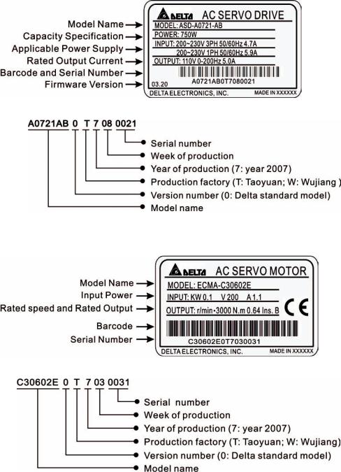
1.2.1 Nameplate Information
ASDA-AB Series Servo Drive
Nameplate Explanation
Serial Number Explanation
ASMT Series Servo Motor
Nameplate Explanation
Serial Number Explanation
1-2 |
Revision January 2009 |
Chapter 1 Unpacking Check and Model Explanation|ASDA-AB Series
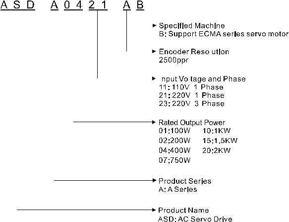
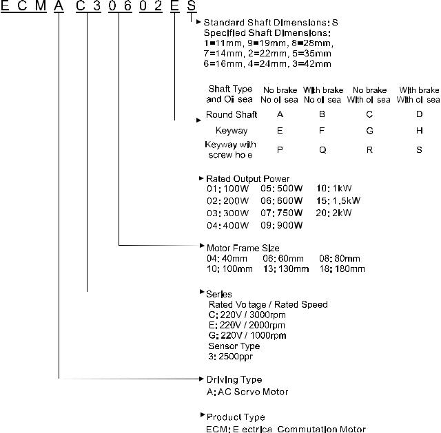
1.2.2 Model Name Explanation
ASDA-AB Series Servo Drive
|
|
|
|
|
|
|
|
|
|
|
|
|
|
|
|
|
|
|
|
|
|
|
|
|
|
|
|
|
|
|
|
|
|
|
|
|
|
|
|
|
|
|
|
|
|
|
|
|
|
|
|
|
|
|
|
|
|
|
|
|
|
|
|
|
|
|
|
|
|
|
|
|
|
|
|
|
|
|
|
|
|
|
|
|
|
|
|
|
|
|
|
|
|
|
|
|
|
|
|
|
|
|
|
|
|
|
|
|
|
|
|
|
|
|
|
|
|
|
|
|
|
|
|
|
|
|
|
|
|
|
|
|
|
|
|
|
|
|
|
|
|
|
|
|
|
|
|
|
|
|
|
|
|
|
|
|
|
|
|
Revision January 2009 |
1-3 |
||||||||||||||
Chapter 1 Unpacking Check and Model Explanation|ASDA-AB Series
ECMA Series Servo Motor
1-4 |
|
|
|
|
|
|
|
|
|
|
|
|
|
|
|
|
|
|
|
|
|
|
|
|
|
|
|
|
|
|
|
|
|
|
|
|
|
|
|
|
|
|
|
|
|
|
|
|
|
|
|
|
|
|
|
|
|
|
|
|
|
|
|
|
|
|
|
|
|
|
|
|
|
|
|
|
|
|
|
|
|
|
|
|
|
|
|
|
|
|
|
|
|
|
|
|
|
|
|
|
|
|
|
|
|
|
|
|
|
|
|
|
|
|
|
|
|
|
|
|
|
|
|
|
|
|
|
|
|
|
|
|
|
|
|
|
|
|
|
|
|
|
|
|
|
|
|
|
|
|
|
|
|
|
|
|
|
|
|
|
|
|
|
|
|
|
|
|
|
|
|
|
|
|
|
|
|
|
|
|
|
|
|
|
|
|
|
|
|
|
|
|
|
|
|
|
|
|
|
|
|
|
|
|
|
|
|
|
|
|
|
|
|
|
|
|
|
|
|
|
|
|
|
|
|
|
|
|
|
|
|
|
|
|
|
|
|
|
|
|
|
|
|
|
|
|
|
|
|
|
|
|
|
|
|
|
|
|
|
|
|
|
|
|
|
|
|
|
|
|
|
|
|
|
|
|
|
|
|
|
|
|
|
|
|
|
|
|
|
|
|
|
|
|
|
|
|
|
|
|
|
|
|
|
Revision January 2009 |
||||||
|
|
|
|
|
|
|
|
|
|
|
|
|
|
|
|
|
|
|
|||||||
|
|
|
|
|
|
|
|
|
|
|
|
|
|
|
|
|
|
|
|||||||
|
|
|
|
|
|
|
|
|
|
|
|
|
|
|
|
|
|
|
|||||||
|
|
|
|
|
|
|
|
|
|
|
|
|
|
|
|
|
|
|
|||||||
|
|
|
|
|
|
|
|
|
|
|
|
|
|
|
|
|
|
|
|||||||
Chapter 1 Unpacking Check and Model Explanation|ASDA-AB Series
1.3Servo Drive and Servo Motor Combinations
The table below shows the possible combination of Delta ASDA-AB series servo drives and ECMA series servo motors. The boxes ( ) in the model names are for optional configurations. (Please refer to Section 1.2 for model explanation)
Power |
Servo Drive |
Servo Motor |
|
100W |
ASD-A0111-AB |
ECMA-C30401 S (S=8mm) |
|
ASD-A0121-AB |
|||
|
|
||
|
|
|
|
200W |
ASD-A0211-AB |
ECMA-C30602 S (S=14mm) |
|
ASD-A0221-AB |
|||
|
|
||
|
|
ECMA-C30604 S (S=14mm) |
|
400W |
ASD-A0411-AB |
ECMA-C30804 7 (7=14mm) |
|
ASD-A0421-AB |
ECMA-E31305 S (S=22mm) |
||
|
|||
|
|
ECMA-G31303 S (S=22mm) |
|
|
|
|
|
750W |
ASD-A0721-AB |
ECMA-C30807 S (S=19mm) |
|
ECMA-G31306 S (S=22mm) |
|||
|
|
||
|
|
ECMA-C31010 S (S=22mm) |
|
1000W |
ASD-A1021-AB |
ECMA-E31310 S (S=22mm) |
|
|
|
ECMA-G31309 S (S=22mm) |
|
|
|
|
|
1500W |
ASD-A1521-AB |
ECMA-E31315 S (S=22mm) |
|
|
|
ECMA-C31020 S (S=22mm) |
|
2000W |
ASD-A2023-AB |
ECMA-E31320 S (S=22mm) |
|
|
|
ECMA-E31820 S (S=35mm) |
|
|
|
|
The servo drives shown in the above table are designed for use in combination with the specific servo motors. Check the specifications of the drives and motors you want to use.
Also, please ensure that both the servo drive and motor are correctly matched for size (power rating). If the power of motor and drive is not within the specifications, the drive and motor may overheat and servo alarm would be activated. For the detail specifications of servo drives and motors, please refer to Chapter 11 “Specifications”.
The drives shown in the above table are designed according to the three multiple of rated current of motors shown in the above table. If the drives which are designed according to the six multiple of rated current of motors are needed, please contact our distributors or your local Delta sales representative.
Revision January 2009 |
1-5 |
Chapter 1 Unpacking Check and Model Explanation|ASDA-AB Series
1.4Servo Drive Features
220V models
1-6
Revision January 2009
Chapter 1 Unpacking Check and Model Explanation|ASDA-AB Series
110V models
Revision January 2009 |
1-7 |
Chapter 1 Unpacking Check and Model Explanation|ASDA-AB Series
1.5Control Modes of Servo Drive
The Delta Servo provides six single and five dual modes of operation.
Their operation and description is listed in the following table.
|
Mode |
Code |
Description |
|
|
|
|
|
External Position Control |
Pt |
External Position control mode for the servo motor is |
|
achieved via an external pulse command. |
||
|
|
|
|
|
|
|
Internal Position control mode for the servo motor is |
|
Internal Position Control |
Pr |
achieved via 8 internal position registers within the servo |
|
controller. Execution of the 8 positions is via Digital Input |
||
|
|
|
|
|
|
|
(DI) signals. |
|
|
|
|
|
|
|
(External / Internal) Speed control mode for the servo motor |
|
|
|
can be achieved via parameters set within the controller or |
|
Speed Control |
S |
from an external analog -10 ~ +10 VDC command. Control |
|
|
|
of the internal speed mode is via the Digital Inputs (DI). (A |
|
|
|
maximum of three speeds can be stored internally). |
|
|
|
|
Single |
|
|
Internal Speed control mode for the servo motor is only |
Mode |
Internal Speed Control |
Sz |
achieved via parameters set within the controller. Control of |
|
|
|
the internal speed mode is via the Digital Inputs (DI). (A |
|
|
|
maximum of three speeds can be stored internally). |
|
|
|
|
|
|
|
(External / Internal) Torque control mode for the servo |
|
|
|
motor can be achieved via parameters set within the |
|
Torque Control |
T |
controller or from an external analog -10 ~ +10 VDC |
|
command. Control of the internal torque mode is via the |
||
|
|
|
|
|
|
|
Digital Inputs (DI). (A maximum of three torque levels can |
|
|
|
be stored internally). |
|
|
|
|
|
|
Tz |
Internal Torque control mode for the servo motor is only |
|
Internal Torque Control |
|
achieved via parameters set within the controller. Control of |
|
|
the internal torque mode is via the Digital Inputs (DI). (A |
|
|
|
|
|
|
|
|
maximum of three torque levels can be stored internally). |
|
|
|
|
|
|
Pt-S |
Either Pt or S control mode can be selected via the Digital |
|
|
|
Inputs (DI) |
|
|
Pt-T |
Either Pt or T control mode can be selected via the Digital |
|
|
|
Inputs (DI) |
|
|
|
|
|
Dual Mode |
Pr-S |
Either Pr or S control mode can be selected via the Digital |
|
|
Inputs (DI) |
|
|
|
|
|
|
|
Pr-T |
Either Pr or T control mode can be selected via the Digital |
|
|
|
Inputs (DI) |
|
|
S-T |
Either S or T control mode can be selected via the Digital |
|
|
|
Inputs (DI) |
The above control modes can be accessed and changed via parameter P1-01. Enter the new control mode via P1-01 then switch the main power to the servo drive OFF then ON. The new control mode will only be valid after the drives main power is switched OFF then ON. Please see safety precautions on page iii (switching drive off/on multiple times).
1-8 |
Revision January 2009 |

Chapter 2 Installation and Storage
2.1Installation Notes
Please pay close attention to the following installation notes:
Do not bend or strain the connection cables between servo drive and motor.
When mounting the servo drive, make sure to tighten all screws to secure the drive in place.
If the servo motor shaft is coupled directly to a rotating device ensure that the alignment specifications of the servo motor, coupling, and device are followed. Failure to do so may cause unnecessary loads or premature failure to the servo motor.
If the length of cable connected between servo drive and motor is more than 20m, please increase the wire gauge of the encoder cable and motor connection cable (connected to U, V, W terminals).
Make sure to tighten the screws for securing motor.
2.2Storage Conditions
The product should be kept in the shipping carton before installation. In order to retain the warranty coverage, the AC servo drive should be stored properly when it is not to be used for an extended period of time. Some storage suggestions are:
Store in a clean and dry location free from direct sunlight.
Store within an ambient temperature range of -20°C to +65°C (-4°F to 149°F).
Store within a relative humidity range of 0% to 90% and non-condensing.
Do not store in a place subjected to corrosive gases and liquids.
Store in original packaging and placed on a solid surface.
Revision January 2009 |
2-1 |
Chapter 2 Installation and Storage|ASDA-AB Series
2.3Installation Conditions
Operating Temperature |
|
|
ASDA-AB Series Servo Drive |
: |
0°C to 55°C (32°F to 131°F) |
ECMA Series Servo Motor |
: |
0°C to 40°C (32°F to 104°F) |
The ambient temperature of servo drive should be under 45°C (113°F) for long-term reliability.
If the ambient temperature of servo drive is greater than 45°C (113°F), please install the drive in a wellventilated location and do not obstruct the airflow for the cooling fan.
Caution
The servo drive and motor will generate heat. If they are installed in a control panel, please ensure sufficient space around the units for heat dissipation.
Pay particular attention to vibration of the units and check if the vibration has impacted the electric devices in the control panel. Please observe the following precautions when selecting a mounting location. Failure to observe the following precautions may void the warranty!
Do not mount the servo drive or motor adjacent to heat-radiating elements or in direct sunlight.
Do not mount the servo drive or motor in a location subjected to corrosive gases, liquids, airborne dust or metallic particles.
Do not mount the servo drive or motor in a location where temperatures and humidity will exceed specification.
Do not mount the servo drive or motor in a location where vibration and shock will exceed specification.
Do not mount the servo drive or motor in a location where it will be subjected to high levels of electromagnetic radiation.
2-2 |
Revision January 2009 |
Chapter 2 Installation and Storage|ASDA-AB Series
2.4Installation Procedure and Minimum Clearances
Installation Procedure
Incorrect installation may result in a drive malfunction or premature failure of the drive and or motor. Please follow the guidelines in this manual when installing the servo drive and motor.
The ASDA-AB servo drive should be mounted perpendicular to the wall or in the control panel. In order to ensure the drive is well ventilated, ensure that the all ventilation holes are not obstructed and sufficient free space is given to the servo drive. Do not install the drive in a horizontal position or malfunction and damage will occur.
Drive Mounting
The ASDA-AB Servo drives must be back mounted vertically on a dry and solid surface such as a NEMA enclosure. A minimum spacing of two inches must be maintained above and below the drive for ventilation and heat dissipation. Additional space may be necessary for wiring and cable connections. Also, as the drive conducts heat away via the mounting, the mounting plane or surface should not conduct heat into the drive from external sources
Motor Mounting
The ECMA Servo motors should be mounted firmly to a dry and solid mounting surface to ensure maximum heat transfer for maximum power output and to provide a good ground.
For the dimensions and weights specifications of servo drive or motor, please refer to Chapter 11 “Specifications".
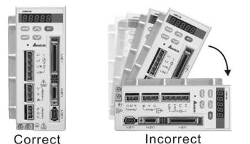
Minimum Clearances
Install a fan to increase ventilation to avoid ambient temperatures that exceed the specification. When installing two or more drives adjacent to each other please follow the clearances as shown in the following diagram.
Revision January 2009 |
2-3 |
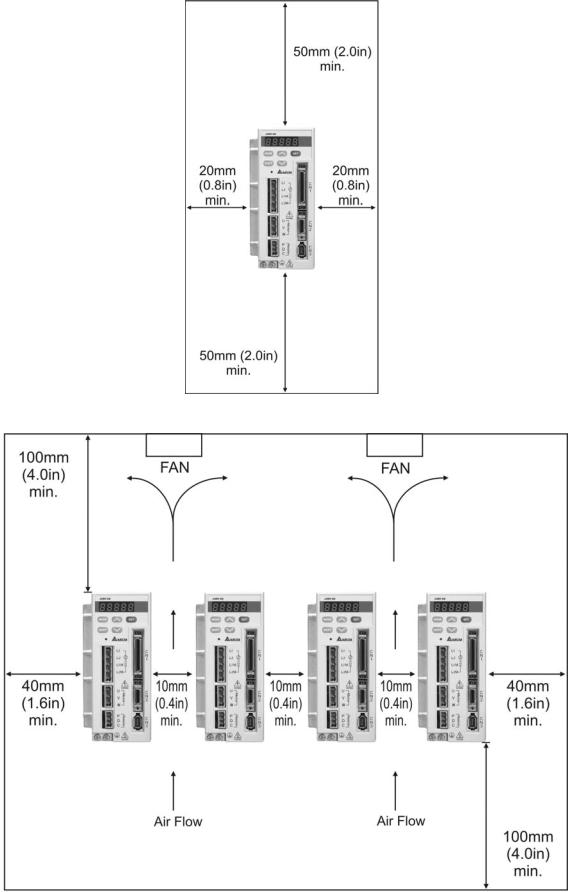
Chapter 2 Installation and Storage|ASDA-AB Series
Minimum Clearances
Side by Side Installation
2-4
Revision January 2009
Chapter 3 Connections and Wiring
This chapter provides information on wiring ASDA-AB series products, the descriptions of I/O signals and gives typical examples of wiring diagrams.
3.1Connections
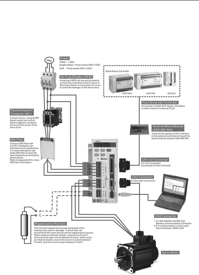
3.1.1 Connecting to Peripheral Devices
Figure 3.1 220V Servo Drive
Revision January 2009 |
3-1 |
Chapter 3 Connections and Wiring|ASDA-AB Series
Figure 3.2 110V Servo Drive
3-2
Revision January 2009
|
|
|
|
|
|
|
|
|
|
|
|
|
Chapter 3 Connections and Wiring|ASDA-AB Series |
|||||||
3.1.2 Servo Drive Connectors and Terminals |
|
|
||||||||||||||||||
|
|
|
|
|
|
|
|
|
|
|
|
|
|
|
|
|
|
|
|
|
|
|
|
|
|
|
Terminal |
Terminal |
|
|
|
|
|
|
Notes |
||||||
|
|
|
|
Identification |
Description |
|
|
|
|
|
|
|||||||||
|
|
|
|
|
|
|
|
|
|
|
|
|||||||||
|
L1, L2 |
Control circuit |
Used to connect single-phase AC control circuit power. |
|||||||||||||||||
|
terminal |
(Control circuit uses the same voltage as the main circuit.) |
||||||||||||||||||
|
|
|
|
|
|
|
|
|
|
|
|
|||||||||
|
|
|
|
|
|
|
|
|
|
|
|
|
|
|
|
|
|
|
|
|
|
R, S, T |
|
Used to connect single-phase or three-phase AC main |
|||||||||||||||||
|
|
circuit power depending on connecting servo drive model. |
||||||||||||||||||
|
(for 220V models) |
Main circuit |
For single-phase 220V models, connect R and S terminals |
|||||||||||||||||
|
|
|
|
|
|
|
|
|
|
|
|
to power. For single-phase 110V models, connect L1M and |
||||||||
|
|
|
|
|
|
|
|
|
|
|
|
|||||||||
|
L1M, L2M |
terminal |
L2M terminals to power. For three-phase models, connect |
|||||||||||||||||
|
|
all three R, S, and T terminals to power. To provide control |
||||||||||||||||||
|
(for 110V models) |
|
circuit power, two jumpers can be added from R and S to |
|||||||||||||||||
|
|
|
|
|
|
|
|
|
|
|
|
|
L1 and L2. |
|
|
|||||
|
|
|
|
|
|
|
|
|
|
|
|
|
Used to connect servo motor |
|||||||
|
|
|
|
|
|
|
|
|
|
|
|
|
|
|
|
|
|
|
|
|
|
|
|
|
|
|
|
|
|
|
|
|
|
Terminal Symbol |
Wire Color |
|
|||||
|
U, V, W |
Servo motor output |
U |
Red |
|
|||||||||||||||
|
|
|
|
|
|
|
|
|
|
|
|
V |
White |
|
||||||
|
|
|
|
|
|
|
|
|
|
|
|
|
|
|||||||
|
FG ( |
|
) |
|
|
|
|
|
|
|
|
|
||||||||
|
|
|
|
|
|
|
|
|
|
|
|
|
W |
Black |
|
|||||
|
|
|
|
|
|
|
|
|
|
|
|
|
|
|
|
|
|
|
|
|
|
|
|
|
|
|
|
|
|
|
|
|
|
FG( |
|
|
|
|
) |
Green |
|
|
|
|
|
|
|
|
|
|
|
|
|
|
|
|
|
|
|
|||
|
|
|
|
|
|
|
|
|
|
|
|
|
|
|
|
|
|
|||
|
|
|
|
|
|
|
|
|
|
|
|
|
Internal resistor |
Ensure the circuit is closed between P |
||||||
|
|
|
|
|
|
|
|
|
|
|
|
|
and D, and the circuit is open between |
|||||||
|
P, D, C |
Regenerative |
|
|
|
|
|
|
P and C. |
|||||||||||
|
resistor terminal |
External resistor |
Connect regenerative resistor to P and |
|||||||||||||||||
|
|
|
|
|
|
|
|
|
|
|
|
|||||||||
|
|
|
|
|
|
|
|
|
|
|
|
|
C, and ensure an open circuit between |
|||||||
|
|
|
|
|
|
|
|
|
|
|
|
|
|
|
|
|
|
|
P and D. |
|
|
|
|
|
|
|
|
|
|
|
|
|
|
|
|
|
|
|
|
|
|
|
|
|
|
|
|
two places |
Ground terminal |
Used to connect grounding wire of power supply and servo |
||||||||||||
|
|
|
|
|
|
|||||||||||||||
|
|
|
|
|
|
motor. |
|
|
||||||||||||
|
|
|
|
|
|
|
|
|
|
|
|
|
|
|
||||||
|
|
|
|
|
|
|
|
|
|
|
|
|
|
|||||||
|
CN1 |
I/O connector |
Used to connect external controllers. Please refer to section |
|||||||||||||||||
|
3.3 for details. |
|
|
|||||||||||||||||
|
|
|
|
|
|
|
|
|
|
|
|
|
|
|
||||||
|
|
|
|
|
|
|
|
|
|
|
|
|
|
|||||||
|
|
|
|
|
|
|
|
|
|
|
|
|
Used to connect encoder of servo motor. Please refer to |
|||||||
|
|
|
|
|
|
|
|
|
|
|
|
|
section 3.4 for details. |
|||||||
|
|
|
|
|
|
|
|
|
|
|
|
|
|
|
||||||
|
|
|
|
|
|
|
|
|
|
|
|
|
Terminal Symbol |
Wire Color |
|
|||||
|
|
|
|
|
|
|
|
|
|
|
|
|
A |
Black |
|
|||||
|
|
|
|
|
|
|
|
|
|
|
|
|
|
|
|
|||||
|
|
|
|
|
|
|
|
|
|
|
|
|
/A |
Black/Red |
|
|||||
|
|
|
|
|
|
|
|
|
|
|
|
|
|
|
|
|||||
|
CN2 |
Encoder connector |
B |
White |
|
|||||||||||||||
|
|
|
|
|
|
|
|
|
||||||||||||
|
/B |
White/Red |
|
|||||||||||||||||
|
|
|
|
|
|
|
|
|
|
|
|
|
|
|||||||
|
|
|
|
|
|
|
|
|
|
|
|
|
|
|
|
|||||
|
|
|
|
|
|
|
|
|
|
|
|
|
Z |
Orange |
|
|||||
|
|
|
|
|
|
|
|
|
|
|
|
|
|
|
|
|||||
|
|
|
|
|
|
|
|
|
|
|
|
|
/Z |
Orange/Red |
|
|||||
|
|
|
|
|
|
|
|
|
|
|
|
|
|
|
|
|||||
|
|
|
|
|
|
|
|
|
|
|
|
|
+5V |
Brown & Brown/White |
|
|||||
|
|
|
|
|
|
|
|
|
|
|
|
|
|
|
|
|||||
|
|
|
|
|
|
|
|
|
|
|
|
|
GND |
Blue & Blue/White |
|
|||||
|
|
|
|
|
|
|
|
|
|
|
|
|
|
|
|
|||||
|
CN3 |
Communication |
Used to connect PC or keypad. Please refer to section 3.5 |
|||||||||||||||||
|
connector |
for details. |
|
|
||||||||||||||||
|
|
|
|
|
|
|
|
|
|
|
|
|
|
|||||||


 NOTE
NOTE
1) U, V ,W , CN1, CN2, CN3 terminals provide short circuit protection.
Revision January 2009 |
3-3 |
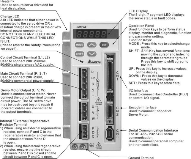
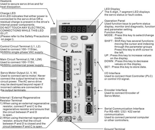
Chapter 3 Connections and Wiring|ASDA-AB Series
Wiring Notes
Please observe the following wiring notes while performing wiring and touching any electrical connections on the servo drive or servo motor.
1.Please note that the main circuit terminals of 110V models are L1M and L2M, and there is no terminal T in 110V models. In other words, the terminal T in 220V models becomes no function in 110V models.
2.Ensure to check if the power supply and wiring of the "power" terminals (R(L1M), S(L2M), T, U, V, & W) is correct.
3.Please use shielded twisted-pair cables for wiring to prevent voltage coupling and eliminate electrical noise and interference.
4.As a residual hazardous voltage may remain inside the drive, please do not immediately touch any of the "power" terminals (R(L1M), S(L2M), T, U, V, & W) and/or the cables connected to them after the power has been turned off and the charge LED is lit. (Please refer to the Safety Precautions on page ii).
5.The cables connected to R(L1M), S(L2M), T and U, V, W terminals should be placed in separate conduits from the encoder or other signal cables. Separate them by at least 30cm (11.8 inches).
6.If the encoder cable is too short, please use a twisted-shield signal wire with grounding conductor. The wire length should be 20m (65.62ft.) or less. For lengths greater than 20m (65.62ft.), the wire gauge should be doubled in order to lessen any signal attenuation.
7.As for motor cable selection, please use the 600V PTFE wire and the wire length should be less than 98.4ft. (30m). If the wiring distance is longer than 30m (98.4ft.), please choose the adequate wire size according to the voltage.
8.The shield of shielded twisted-pair cables should be connected to the SHIELD end (terminal marked  ) of the servo drive.
9.For the connectors and cables specifications, please refer to section 3.1.6 for details.
3-4 |
Revision January 2009 |
Chapter 3 Connections and Wiring|ASDA-AB Series
3.1.3 Wiring Methods
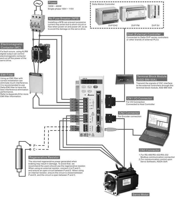
For servo drives from 100W to 1.5kW the input power can be either single or three-phase. For servo drives 2kW and above only three-phase connections are available. But, 220V single-phase models are available in 1.5kW and below only and 110V single-phase models are available in 400W and below only.
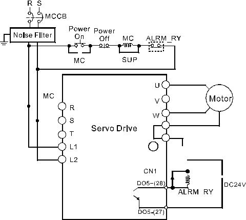
In the wiring diagram figures 3.3, 3.4 & 3.5:
Power ON : contact “a” (normally open)
Power OFF : contact “b” (normally closed)
MC : coil of electromagnetic contactor, self-holding power, contact of main circuit power
Figure 3.3 Single-Phase Power Supply (1.5kW and below, 220V models)
|
|
|
|
|
|
|
|
|
|
|
|
|
|
|
|
|
|
|
|
|
|
|
|
|
|
|
|
|
|
|
|
|
|
|
|
|
|
|
|
|
|
|
|
|
|
|
|
|
|
|
|
|
|
|
|
|
|
|
|
|
|
|
|
|
|
|
|
|
|
|
|
|
|
|
|
|
|
|
|
|
|
|
|
|
|
|
|
|
|
|
|
|
|
|
|
|
|
|
|
|
|
|
|
|
|
|
|
|
|
|
|
|
|
|
|
|
|
|
|
|
|
|
|
|
|
|
|
|
|
|
|
|
|
|
|
|
|
|
|
|
|
|
|
|
|
|
|
|
|
|
|
|
|
|
|
|
|
|
|
|
|
|
|
|
|
|
|
|
|
|
|
|
|
|
|
|
|
|
|
|
|
|
|
|
|
|
|
|
|
|
|
|
|
|
|
|
|
|
|
|
|
|
|
|
|
|
|
|
|
|
|
|
|
|
|
|
|
|
|
|
|
|
|
|
|
|
|
|
|
|
|
|
|
|
|
|
|
|
|
|
|
|
|
|
|
|
|
|
|
|
|
|
|
|
|
|
|
|
|
|
|
|
|
|
|
|
|
|
|
|
|
|
|
|
|
|
|
|
|
|
|
|
|
|
|
|
|
|
|
|
|
|
|
|
|
|
|
|
|
|
|
|
|
|
|
|
|
|
|
|
|
|
|
|
|
|
|
|
|
|
|
|
|
|
|
|
|
|
|
|
|
|
|
|
|
|
|
|
|
|
|
|
|
|
|
|
|
|
|
|
|
|
|
|
|
|
|
|
|
|
|
|
|
|
|
|
|
|
|
|
|
|
|
|
|
|
|
|
|
|
|
|
|
|
|
|
|
|
|
|
|
|
|
|
|
|
|
|
|
|
|
|
|
|
|
|
|
|
|
|
|
|
|
|
|
|
|
|
|
|
|
|
|
|
|
|
|
|
|
|
|
|
|
|
|
|
|
|
|
|
|
|
|
|
|
|
|
|
|
|
|
|
|
|
|
|
|
|
|
|
|
|
|
|
|
|
|
|
|
|
|
|
|
|
|
|
|
|
|
|
|
|
|
|
|
|
|
|
|
|
|
|
|
|
|
|
|
|
|
|
|
|
|
|
|
|
|
|
|
|
|
|
|
|
|
|
|
|
|
|
|
|
|
|
|
|
|
|
|
|
|
|
|
|
|
|
|
|
|
|
|
|
|
|
|
|
|
|
|
|
|
|
|
|
|
|
|
|
|
|
|
|
|
|
|
|
|
|
|
|
|
|
|
|
|
|
|
|
|
|
|
|
|
|
|
|
|
|
|
|
|
|
|
|
|
|
|
|
|
|
|
|
|
|
|
|
|
|
|
|
|
|
|
|
|
|
|
|
|
|
|
|
|
|
|
|
|
|
|
|
|
|
|
|
|
|
|
|
|
|
|
|
|
|
|
|
|
|
|
|
|
|
|
|
|
|
|
|
|
|
|
|
|
|
|
|
|
|
|
|
|
|
|
|
|
|
|
|
|
|
|
|
|
|
|
|
|
|
|
|
|
|
|
|
|
|
|
|
|
|
|
|
|
|
|
|
|
|
|
|
|
|
|
|
|
|
|
|
|
|
|
|
|
|
|
|
|
|
|
|
|
|
|
|
|
|
|
|
|
|
|
|
|
|
|
|
|
|
|
|
|
|
|
|
|
|
|
|
|
|
|
|
|
|
|
|
|
|
|
|
|
|
|
|
|
|
Revision January 2009 |
3-5 |
|||||||||||||||||||||||||||||||||||
Loading...