


INSTALLATION and SERVICE INSTRUCTIONS
USE and CARE
 INSTRUCTIONS
BUILT-IN
GAS ON GLASS HOBS
Models:
DEGH60BG - DEGH70BG - DEGH90BG
distributed by DèLonghi Pty Ltd
2
Dear Customer,
Thank you for having purchased and given your preference to our product.
The safety precautions and recommendations reported below are for your own safety and that of others. They will also provide a means by which to make full use of the features offered by your appliance.
Please keep this booklet in a safe place. It may be useful in future, either to yourself or to others in the event that doubts should arise relating to its operation.
This appliance must be used only for the task it has explicitly been designed for, that is for cooking foodstuffs. Any other form of usage is to be considered as inappropriate and therefore dangerous.
The manufacturer declines all responsibility in the event of damage caused by improper, incorrect or illogical use of the appliance or be faulty installation.
PRODUCT LABEL
This cooktop has been designed and constructed in accordance with the following codes
AGA101 (AS 4551) Approval Requirements for Domestic Gas cooking appliances AS/NZS 60335.1 General Requirements for Domestic electrical appliances AS/NSZ 60335.2.6 Particular Requirements for Domestic electrical cooking appliances AS/NZS CISPR 14.1 Electromagnetic Compatibility Requirements
3
IMPORTANT PRECAUTIONS AND RECOMMENDATIONS FOR USE OF ELECTRICAL APPLIANCES
Use of any electrical appliance implies the necessity to follow a series of fundamental rules. In particular:
Never touch the appliance with wet hands or feet.
Do not operate the appliance barefooted.
supervision.
Young children should be supervised to ensure they do not play with the appliance.
The manufacturer cannot be held responsible for any damages caused by improper, incorrect or illogical use of the appliance.
IMPORTANT PRECAUTIONS AND RECOMMENDATIONS
After having unpacked the appliance, check to ensure that it is not damaged.
- nician.
Packing elements (i.e. plastic bags, polystyrene foam, nails, packing straps, etc.) should not be left around within easy reach of children, as these may cause serious injuries.
Do not attempt to modify the technical characteristics of the appliance as this may become dangerous to use.
Do not carry out cleaning or maintenance operations on the appliance without having previously disconnected it from the electric power supply.
After use, ensure that the knobs are in the off position.
During and after use of the appliance, certain parts will become very hot. Do not touch hot parts.
Household appliances are not intended to be played with by children.
Keep children away from the appliance when it is in use.
Children, or persons with a disability which limits their ability to use the appliance, should have a responsible person to instruct them in its use. The instructor should surroundings.
!!
WARNING: When correctly installed, your product meets all safety requirements laid down for this type of product category. However special care should be taken around the rear or the underneath of the appliance as these areas are not designed or intended to be touched and may contain sharp or rough edges, that may cause injury.
This appliance is for domestic use only.
Do not use the hob if the glass surface is broken or cracked in any way.
"Please disconnect the hob from the mains and contact the After-Sales Service.
Do not scratch the hob with sharp objects. Don’t use the hob as a work surface.
The manufacturer declines all liability for injury to persons or damage to property caused by incorrect or improper use of the appliance.
IMPORTANT NOTE: This appliance shall not be used as a space heater, especially if installed in marine craft or caravans.
4

INSTALLATION
CAUTION:
This appliance must be installed in accordance with these installation instruc-- lations, electrical wiring regulations, - Gas Installations and ony other relevant statutory regulations.
This appliance shall be only be serviced by authorized personnel.
This appliance is to be installed only by an authorised person.
Incorrect installation, for which the manufacturer accepts no responsibility, may cause personal injury of damage.
Always disconnect the appliance from mains power supply before carrying out any maintenance operations or repairs.
In the room where the appliance is installed, there must be enough air to allow the gas to burn correctly, according to the current local regulations.
ELECTRICAL REQUIREMENTS
The appliance must be connected to the mains checking that the voltage corresponds to the value given in the rating plate and that the electrical cable sections can!
The plug must be connected to an earthed socket in compliance with safety standards.
powerconsumed by the appliance.
The wires in the power cable are coloured in accordance with the following code:
"Green/Yellow = Earth, Blue = Neutral, Brown = Active.
"If the colours of the wires in the power cable to the appliance do not correspond with the coloured markings identifying the terminals in the junction terminal, proceed as follows:
1.The wire which is coloured green and yellow must be connected to the terminal marked E (Earth) or coloured Green.
2.The wire which is coloured blue must be connected to the terminal marked N (Neutral) or coloured Black.
3.The wire which is coloured brown must be connected to the terminal marked L (Live) or A (Active) or coloured Red.
A suitable isolating switch providing full disconnection from the mains power supply (under overvoltage category III conditions) shall be incorporated in the permanent wiring, mounted and positioned to comply with the local wiring rules and regulations. The isolating switch must be of an approved type and provide a 3 mm air gap contact separation in all poles (or in all active [phase] conductors if the local wiring rules allow for this variation of the requirements).
The power supply cable must not touch the hot parts and must be positioned so that it does not exceed 50°C above ambient.
Once the appliance has been installed, the switch or socket must always be accessible.
If the supply cord is damaged it must be replaced by the manufacturer or it’s Service
# $ !
5
N.B. The connection of the appliance to earth is mandatory.
- trician.
He should also check that the socket cable section is suitable for the power drawn by the appliance.
withthe instructions supplied by the manufacturer and in compliance with established electrical regulations.
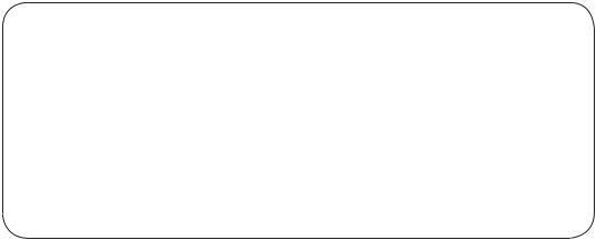
Figure 1 |
Figure 2 |
Models: DEGH60BG, |
|
|
||
|
DEGH90BG |
|
|
|
ELECTRIC DIAGRAM KEY |
|
|||
A |
Ignition coil |
|
|
|
PA |
Ignition switches group |
|||
CA |
Spark electrodes |
|
|
|
M |
Terminal block |
|
|
|
Only for the model |
M |
|
|
|
|
N |
L |
||
DEGH90BG |
|
|
|
|
A |
|
|
|
|
|
CA |
|
|
|
|
|
PA |
|
|
Only for the model DEGH90BG |
|
|
||
6 |
|
|
|
|
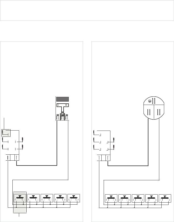
Model: DEGH70BG
ELECTRIC DIAGRAM KEY
AIgnition coil
PA Ignition switches group CA Spark electrodes
MTerminal block
M L N
A
CA
PA
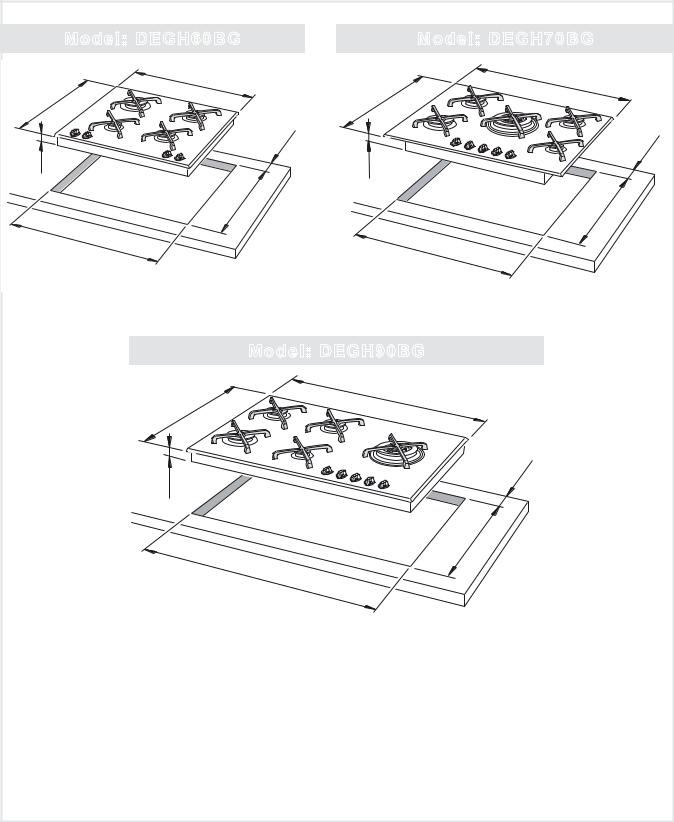
CLEARANCES
Installation clearances and protection of combustible surfaces shall comply with the current local regulations e.g. AS/NZS5601 - Gas Installations code.
Model: DEGH60BG |
|
|
|
Model: DEGH70BG |
585 |
|
|
|
715 |
510 |
|
|
(3) |
510 |
|
|
|
|
|
|
|
(2) |
|
|
(1) |
60 |
|
|
(1) |
54 |
|
|
|
54 |
480 |
|
|
|
480 |
|
|
|
|
|
560 |
|
|
|
|
|
|
|
|
560 |
Figure 3a |
|
|
|
Figure 3b |
|
|
Model: DEGH90BG |
|
|
510 |
869 |
|
|
|
|
|
|
|
|
(3) |
(1) |
|
(2) |
|
54 |
|
60 |
|
|
|
480 |
|
|
|
840 |
|
Figure 3c
60
|
(3) |
(2) |
|
(1)54 mm from top of countertop.
(2)At least 60 mm between the back side of the cut-out and the back of the countertop.
(3)At least 200 mm from the periphery of the nearest burner to any vertical combustible surface. If the distance from the periphery of the nearest burner to any vertical combustible surface, or vertical combustible surface with toughened glass or sheet metal, is less than 200 mm, the surface shall be protected (in accordance with AS/NZS5601) to a height of not less than 150 mm above the hob for the full dimension (width or depth) of the cooking surface area.
Important note:
This appliance shall not be used as a space heater, especially if installed in marine craft or caravans.
7

Model: DEGH60BG
450 mm |
650 mm |
500 |
mm |
|
2,5 Amm minimum
tween the side Model: DEGH70BG
the cut-out
d the side wall
Figure 4a
450 mm |
650 mm |
500 |
mm |
|
60 mm minimum etween the side the cutB-out
nd the side wall
Figure 4b
Model: DEGH90BG
450 |
650 |
500
14 5
C
Figure 4c
A.212.5 mm minimum between the side of the cut-out and the side wall.
B.260 mm minimum between the side of the cut-out and the side wall.
C.214.5 mm minimum between the side of the cut-out and the side wall.
IMPORTANT: see also item (3) at page no.7.
8

The installation shall comply with the dimensions in Figures 3a, 3b or 3c and 4a, 4b or 4c, bearing in mind that:
A partition between the base of the hob and the cupboard below mm below the workbench surface if the cupboard is to be used for storage.
If the hob is installed over a built-in oven, the oven shall be provided with cooling fan motor. The two appliances shall be connected to the gas/electrical supply with independent connections.
Overhead clearances - In no case shall the clearance between the highest part of the hob and a range hood be less than 600 mm, or for an overhead exhaust fan 800 mm. Any other downward facing combustible surface less than 600 mm above the highest part of the hob shall be protected for the full width and depth of the cooking surface area in accordance with local regulations inforce. However, in no case shall this clearance to any surface be less than 450 mm.
Standards requirement
Temperature of nearby surfaces. Australian and New Zealand Gas Installation Standards (AS/NZS5601) require a cooktop to be installed so that the surface temperature of any nearby combustible surface will not exceed 65°C above ambient.
This is typically achieved by:
% & ' ' ' * * * +; " AND
protecting the wall to a height of at least 150 mm along its length (minimum height of non-combustible material when used on adjacent walls) with non-combustible surface materials such as:
–< > % & +;
–tempered glass or sheetmetal, minimum thickness 0.4 mm (acceptable when used+!
INSTALLING THE SEPARA- |
|
Figure 5 |
TOR BELOW THE BASE OF |
|
|
|
|
|
THE COOKTOP |
|
|
It is recommended that a 30 mm |
|
|
clearance be left between to base |
|
|
of the cooktop and the separator. |
|
|
The separator shall be heat resi- |
|
mm |
stant, made of low thermal con- |
Clearance |
|
ductivity material and shall be re- |
|
30 |
movable with the use of a tool for |
Separator |
|
installation and service. |
|
|
|
Space for |
|
|
connections |
|
|
|
9 |
 Loading...