


 Loading...
Dell™ Serial-Attached SCSI 5/iR Integrated and Adapter
User’s Guide
Model UCS-51
w w w . d e l l . c o m | s u p p o r t . d e l l . c o m
Dell™ Serial-Attached SCSI 5/iR Integrated and Adapter
User’s Guide
w w w . d e l l . c o m | s u p p o r t . d e l l . c o m

Notes, Notices, and Cautions
NOTE: A NOTE indicates important information that helps you make better use of your computer.
NOTICE: A NOTICE indicates either potential damage to hardware or loss of data and tells you how to avoid the problem.
 CAUTION: A CAUTION indicates a potential for property damage, personal injury, or death.
____________________
Information in this document is subject to change without notice. © 2005–2007 Dell Inc. All rights reserved.
Reproduction in any manner whatsoever without the written permission of Dell Inc. is strictly forbidden.
Trademarks used in this text: Dell, the DELL logo, Dell Precision, PowerEdge, and OpenManage are trademarks of Dell Inc.; Intel is a registered trademark of Intel Corporation; Microsoft, Windows, and Windows Server are registered trademarks, and Windows Vista is trademark of Microsoft Corporation; Novell NetWare, and SUSE are registered trademarks of Novell, Inc. in the United States and other countries; Red Hat and Red Hat Enterprise Linux are registered trademarks of Red Hat, Inc.; LSI Logic, Fusion-MPT, Integrated Mirroring, and Integrated Striping are trademarks or registered trademarks of LSI Logic Corporation; DR-DOS is a registered trademark of DRDOS, Inc.
Other trademarks and trade names may be used in this document to refer to either the entities claiming the marks and names or their products. Dell Inc. disclaims any proprietary interest in trademarks and trade names other than its own.
Model UCS-51
January 2007 P/N YD912 |
Rev. A01 |

Contents
CAUTION: Safety Instructions. . . . . . . . . . . . . . . . . . . . . |
7 |
SAFETY: General . . . . . . . . . . . . . . . . . . . . . . . . . . . . . . . . . . |
7 |
SAFETY: When Working Inside Your System . . . . . . . . . . . . . . . . . . . |
7 |
SAFETY: Protecting Against Electrostatic Discharge . . . . . . . . . . . . . . . |
8 |
1 |
Overview . . . . . . . . . . . . . . . . . . . . . . . . . . . . . . . . . . . |
9 |
|
About RAID . . . . . . . . . . . . . . . . . . . . . . . . . . . . . . . . . . . . |
10 |
|
RAID Levels . . . . . . . . . . . . . . . . . . . . . . . . . . . . . . . . . |
10 |
|
RAID Terminology . . . . . . . . . . . . . . . . . . . . . . . . . . . . . . . . |
10 |
|
Integrated Striping . . . . . . . . . . . . . . . . . . . . . . . . . . . . . |
10 |
|
Integrated Mirroring . . . . . . . . . . . . . . . . . . . . . . . . . . . . |
11 |
2SAS 5/iR Features . . . . . . . . . . . . . . . . . . . . . . . . . . . . . 13
3Hardware Installation . . . . . . . . . . . . . . . . . . . . . . . . . . 15
Installing the SAS 5/iR Adapter . . . . . . . . . . . . . . . . . . . . . . . . . |
15 |
4 Driver Installation . . . . . . . . . . . . . . . . . . . . . . . . . . . . . |
19 |
Creating a Driver Diskette . . . . . . . . . . . . . . . . . . . . . . . . . . . . |
19 |
Installing the Driver During Windows Operating |
|
System Installation . . . . . . . . . . . . . . . . . . . . . . . . . . . . . . . . |
20 |
Installing a Windows Driver for a New SAS 5/iR Controller . . . . . . . . . . |
20 |
Updating an Existing Windows Driver . . . . . . . . . . . . . . . . . . . . . |
21 |
Installing From the Dell Operating System Media . . . . . . . . . . . . . . . |
22 |
Contents 3

|
Installing the Red Hat Enterprise Linux Driver . . . . . . . . . . . . . . . . . |
22 |
|
Creating a Driver Diskette . . . . . . . . . . . . . . . . . . . . . . . . . |
22 |
|
Installing the Driver . . . . . . . . . . . . . . . . . . . . . . . . . . . . . |
23 |
|
Installing the Driver Using an Update RPM. . . . . . . . . . . . . . . . . |
24 |
|
Installing the SUSE Linux Enterprise Server Driver. . . . . . . . . . . . . . . |
24 |
|
Installing the Driver Using an Update RPM. . . . . . . . . . . . . . . . . |
24 |
|
Installing SUSE Linux Enterprise Server Using |
|
|
the Driver Update Diskette . . . . . . . . . . . . . . . . . . . . . . . . . |
25 |
|
Upgrading the Kernel . . . . . . . . . . . . . . . . . . . . . . . . . . . . . . |
26 |
5 |
SAS 5/iR BIOS . . . . . . . . . . . . . . . . . . . . . . . . . . . . . . . . |
27 |
|
POST Messages . . . . . . . . . . . . . . . . . . . . . . . . . . . . . . . . . |
27 |
|
BIOS Fault Code Messages. . . . . . . . . . . . . . . . . . . . . . . . . |
27 |
|
Configuration Utility . . . . . . . . . . . . . . . . . . . . . . . . . . . . . . . |
28 |
|
Starting the Configuration Utility . . . . . . . . . . . . . . . . . . . . . . |
28 |
|
Functions Performed . . . . . . . . . . . . . . . . . . . . . . . . . . . . |
28 |
|
Navigating the Configuration Utility . . . . . . . . . . . . . . . . . . . . |
28 |
|
Integrated RAID Configuration and Management Screens . . . . . . . . . . . |
29 |
|
Select New Virtual Disk Type . . . . . . . . . . . . . . . . . . . . . . . . |
29 |
|
Create New Virtual Disk . . . . . . . . . . . . . . . . . . . . . . . . . . |
29 |
|
View Virtual Disk . . . . . . . . . . . . . . . . . . . . . . . . . . . . . . |
30 |
|
Manage Virtual Disk . . . . . . . . . . . . . . . . . . . . . . . . . . . . |
30 |
|
Exit Screen . . . . . . . . . . . . . . . . . . . . . . . . . . . . . . . . . |
31 |
|
Performing Configuration Tasks . . . . . . . . . . . . . . . . . . . . . . . . . |
31 |
|
Creating an Integrated Striping Virtual Disk . . . . . . . . . . . . . . . . |
31 |
|
Creating a Integrated Mirroring Virtual Disk . . . . . . . . . . . . . . . . |
32 |
|
Viewing Virtual Disk Properties. . . . . . . . . . . . . . . . . . . . . . . |
33 |
|
Synchronizing a Virtual Disk . . . . . . . . . . . . . . . . . . . . . . . . |
33 |
|
Activating a Virtual Disk . . . . . . . . . . . . . . . . . . . . . . . . . . |
34 |
|
Deleting a Virtual Disk . . . . . . . . . . . . . . . . . . . . . . . . . . . |
34 |
|
Replacing and Rebuilding a Degraded Virtual Disk . . . . . . . . . . . . |
34 |
4 Contents

6 |
Troubleshooting . . . . . . . . . . . . . . . . . . . . . . . . . . . . . . |
35 |
|
BIOS Boot Order . . . . . . . . . . . . . . . . . . . . . . . . . . . . . . . . . |
35 |
|
General Problems . . . . . . . . . . . . . . . . . . . . . . . . . . . . . . . . |
35 |
|
Physical Disk Related Issues . . . . . . . . . . . . . . . . . . . . . . . . . . |
36 |
|
Configuration Utility Error Messages . . . . . . . . . . . . . . . . . . . . . . |
37 |
|
BIOS Error Messages . . . . . . . . . . . . . . . . . . . . . . . . . . . . . . |
38 |
A |
Updating the Firmware. . . . . . . . . . . . . . . . . . . . . . . . . . |
41 |
|
Firmware Update Utility . . . . . . . . . . . . . . . . . . . . . . . . . . . . . |
41 |
B |
Getting Help . . . . . . . . . . . . . . . . . . . . . . . . . . . . . . . . . |
43 |
|
Obtaining Assistance . . . . . . . . . . . . . . . . . . . . . . . . . . . . . . |
43 |
|
Technical Support and Customer Service . . . . . . . . . . . . . . . . . |
43 |
|
Online Services . . . . . . . . . . . . . . . . . . . . . . . . . . . . . . . |
44 |
|
Automated Order-Status Service . . . . . . . . . . . . . . . . . . . . . . |
44 |
|
Dell Enterprise Training . . . . . . . . . . . . . . . . . . . . . . . . . . . . . |
45 |
|
Problems With Your Order . . . . . . . . . . . . . . . . . . . . . . . . . . . . |
45 |
|
Product Information . . . . . . . . . . . . . . . . . . . . . . . . . . . . . . . |
45 |
|
Returning Items for Warranty Repair or Credit . . . . . . . . . . . . . . . . . |
45 |
|
Before You Call. . . . . . . . . . . . . . . . . . . . . . . . . . . . . . . . . . |
46 |
C |
Regulatory Notices . . . . . . . . . . . . . . . . . . . . . . . . . . . . |
47 |
|
FCC Notices (U.S. Only) . . . . . . . . . . . . . . . . . . . . . . . . . . . . . |
48 |
|
FCC, Class B. . . . . . . . . . . . . . . . . . . . . . . . . . . . . . . . . |
48 |
|
Industry Canada (Canada Only) . . . . . . . . . . . . . . . . . . . . . . . . . |
49 |
|
Industry Canada, Class B . . . . . . . . . . . . . . . . . . . . . . . . . . |
49 |
Contents 5

CE Notice (European Union) . . . . . . . . . . . . . . . . . . . . . . . . . . . |
49 |
European Union, Class B . . . . . . . . . . . . . . . . . . . . . . . . . . |
49 |
Corporate Contact Details (Taiwan Only) . . . . . . . . . . . . . . . . . . . . |
55 |
Glossary . . . . . . . . . . . . . . . . . . . . . . . . . . . . . . . . . . . . . . |
59 |
Index . . . . . . . . . . . . . . . . . . . . . . . . . . . . . . . . . . . . . . . . . |
65 |
6 Contents

 CAUTION: Safety Instructions
Use the following safety guidelines to help ensure your own personal safety and to help protect your system and working environment from potential damage.
NOTE: See the safety and caution statements in your Product Information Guide that came with your Dell™ PowerEdge™ system or Dell Precision™ workstation.
SAFETY: General
•Observe and follow service markings. Do not service any product except as explained in your user documentation. Opening or removing covers that are marked with the triangular symbol with a lightning bolt may expose you to electrical shock. Components inside these compartments should be serviced only by a trained service technician.
•If any of the following conditions occur, unplug the product from the electrical outlet and replace the part or contact your trained service provider:
–The power cable, extension cable, or plug is damaged.
–An object has fallen into the product.
–The product has been exposed to water.
–The product has been dropped or damaged.
–The product does not operate correctly when you follow the operating instructions.
•Use the product only with approved equipment.
•Operate the product only from the type of external power source indicated on the electrical ratings label. If you are not sure of the type of power source required, consult your service provider or local power company.
•Handle batteries carefully. Do not disassemble, crush, puncture, short external contacts, dispose of in fire or water, or expose batteries to temperatures higher than 60 degrees Celsius (140 degrees Fahrenheit). Do not attempt to open or service batteries; replace batteries only with batteries designated for the product.
SAFETY: When Working Inside Your System
Before you remove the system covers, perform the following steps in the sequence indicated.
CAUTION: Except as expressly otherwise instructed in Dell documentation, only trained service technicians are authorized to remove the system cover and access any of the components inside the system.
NOTICE: To help avoid possible damage to the system board, wait 5 seconds after turning off the system before removing a component from the system board or disconnecting a peripheral device.
1Turn off the system and any devices.
2Ground yourself by touching an unpainted metal surface on the chassis before touching anything inside the system.
3While you work, periodically touch an unpainted metal surface on the chassis to dissipate any static electricity that might harm internal components.
4Disconnect your system and devices from their power sources. To reduce the potential of personal injury or shock, disconnect any telecommunication lines from the system.
Safety Instructions |
|
7 |
|

In addition, take note of these safety guidelines when appropriate:
•When you disconnect a cable, pull on its connector or on its strain-relief loop, not on the cable itself. Some cables have a connector with locking tabs; if you are disconnecting this type of cable, press in on the locking tabs before disconnecting the cable. As you pull connectors apart, keep them evenly aligned to avoid bending any connector pins. Also, before you connect a cable, make sure that both connectors are correctly oriented and aligned.
•Handle components and cards with care. Do not touch the components or contacts on a card. Hold a card by its edges or by its metal mounting bracket. Hold a component such as a microprocessor chip by its edges, not by its pins.
SAFETY: Protecting Against Electrostatic Discharge
Electrostatic discharge (ESD) events can harm electronic components inside your computer. Under certain conditions, ESD may build up on your body or an object, such as a peripheral, and then discharge into another object, such as your computer. To prevent ESD damage, you should discharge static electricity from your body before you interact with any of your computer’s internal electronic components, such as a memory module. You can protect against ESD by touching a metal grounded object (such as an unpainted metal surface on your computer’s I/O panel) before you interact with anything electronic. When connecting a peripheral (including handheld digital assistants) to your computer, you should always ground both yourself and the peripheral before connecting it to the computer. In addition, as you work inside the computer, periodically touch an I/O connector to remove any static charge your body may have accumulated.
You can also take the following steps to prevent damage from electrostatic discharge:
•When unpacking a static-sensitive component from its shipping carton, do not remove the component from the antistatic packing material until you are ready to install the component. Just before unwrapping the antistatic package, be sure to discharge static electricity from your body.
•When transporting a sensitive component, first place it in an antistatic container or packaging.
•Handle all electrostatic sensitive components in a static-safe area. If possible, use antistatic floor pads and work bench pads.
8 Safety Instructions

Overview
The Dell™ Serial-Attached SCSI (SAS) 5/iR controller is Dell’s next generation of controller with integrated redundant array of independent disks (RAID) capabilities. SAS technology is not backward compatible with the previous generation of SCSI devices. The SAS 5/iR Adapter is a half-length, standard-height PCI-E card, while the SAS 5/iR Integrated is embedded in the platform hardware. The SAS 5/iR Adapter is supported on platforms with PCI-E x8 or x16 connectors.
Figure 1-1. SAS 5/iR Adapter Hardware Architecture
2 |
1 |
|
1 SAS x4 internal connector |
2 |
PCI-E connector |
Overview 9
About RAID
RAID is a group of multiple independent physical disks that provide high performance by increasing the number of drives used for saving and accessing data. A RAID disk subsystem improves I/O performance and data availability. The physical disk group appears to the host system as a single storage unit or as multiple logical units. Data throughput improves because multiple disks can be accessed simultaneously. RAID systems also improve data storage availability and fault tolerance.
RAID Levels
Integrated Striping or RAID 0 uses disk striping to provide high data throughput, especially for large files in an environment that requires no data redundancy.
Integrated Mirroring or RAID 1 uses disk mirroring so that data written to one physical disk is simultaneously written to another physical disk. This is good for small databases or other applications that require small capacity, but complete data redundancy.
NOTICE: Lost data on an Integrated Striping virtual disk cannot be recovered in the event of a physical disk failure.
RAID Terminology
Integrated Striping
Integrated Striping (RAID 0) allows you to write data across multiple physical disks instead of just one physical disk. Integrated Striping involves partitioning each physical disk storage space into 64 KB stripes. These stripes are interleaved in a repeated sequential manner. The part of the stripe on a single physical disk is called a stripe element.
For example, in a four-disk system using only Integrated Striping, segment 1 is written to disk 1, segment 2 is written to disk 2, and so on. Integrated Striping enhances performance because multiple physical disks are accessed simultaneously, but Integrated Striping does not provide data redundancy. Figure 1-2 shows an example of Integrated Striping.
Figure 1-2. Example of Integrated Striping (RAID 0)
Stripe element 1 |
Stripe element 2 |
Stripe element 3 |
Stripe element 4 |
Stripe element 5 |
Stripe element 6 |
Stripe element 7 |
Stripe element 8 |
Stripe element 9 |
Stripe element 10 |
Stripe element 11 |
Stripe element 12 |
10 Overview
Integrated Mirroring
With Integrated Mirroring (RAID 1), data written to one disk is simultaneously written to another disk. If one disk fails, the contents of the other disk can be used to run the system and rebuild the failed physical disk. The primary advantage of Integrated Mirroring is that it provides 100 percent data redundancy. Because the contents of the disk are completely written to a second disk, it does not matter if one of the disks fails. Both disks contain the same data at all times. Either physical disk can act as the operational physical disk.
NOTE: Mirrored physical disks improve read performance by read load balance.
Figure 1-3. Example of Integrated Mirroring (RAID 1)
Stripe element 1 Stripe element 2 Stripe element 3 Stripe element 4
Stripe element 1 Duplicated Stripe element 2 Duplicated Stripe element 3 Duplicated Stripe element 4 Duplicated
Overview 11

12 Overview

SAS 5/iR Features
This section provides the specifications of Dell™ Serial-Attached SCSI (SAS) 5/iR controller. The following table compares the specifications of the SAS 5/iR Adapter and SAS 5/iR Integrated.
Table 2-1. Specifications of SAS 5/iR
Specification |
SAS 5/iR Adapter |
SAS 5/iR Integrated |
|
|
|
|
|
SAS technology |
Yes |
Yes |
|
|
|
|
|
Support for x4, x8, or x16 PCI |
Yes |
Yes |
|
Express Host Interface |
|||
|
|
||
|
|
|
|
Form Factor |
Standard-Height, Half-Length PCI |
N/A |
|
Adapter |
|||
|
|
||
|
|
|
|
I/O controller (IOC) |
LSI SAS 1068 |
LSI SAS 1068 |
|
|
|
||
Core Speed: 255 MHz |
Core Speed: 255 MHz |
||
|
|||
|
|
|
|
Operating voltage requirements |
+12V, +3.3V, +3.3Vaux |
+12V, +3.3V, +3.3Vaux |
|
|
|
|
|
Communication to the system |
PCI-E lanes |
System dependent |
|
|
|
|
|
Communication to end devices |
SAS Links |
SAS Links |
|
|
|
|
|
SAS Connectors |
1 x4 Internal |
1 x4 Internal |
|
|
|
|
|
Lead Free |
Yes |
Yes |
|
|
|
|
|
|
Microsoft® Windows® 2000 Server |
Microsoft Windows 2000 Server |
|
|
and Windows Server® 2003 Family, |
and Windows Server® 2003 |
|
|
Windows XP, Windows Vista™, |
Family, Windows XP, |
|
Supported operating systems |
Red Hat® Enterprise Linux |
Windows Vista, Red Hat |
|
|
Versions 3, 4, and 5, SUSE® Linux |
Enterprise Linux Versions 3, 4, |
|
|
Enterprise Server Versions 9 and 10. |
and 5, SUSE Linux Enterprise |
|
|
|
Server Versions 9 and 10. |
|
|
|
|
|
Windows Miniport Interface |
Storport, SCSIport (Windows 2000 |
Storport, SCSIport (Windows |
|
|
and XP 32-bit only) |
2000 and XP 32-bit only) |
|
|
|
|
|
Supported drivers for Linux |
Yes |
Yes |
|
|
|
|
|
Dell-compliant SAS and SATA |
Yes |
Yes |
|
compatibility |
|||
|
|
||
|
|
|
|
Dell supported direct connected |
Dell-compliant physical disks |
Dell-compliant physical disks |
|
end devices |
|
|
SAS 5/iR Features |
13 |

Table 2-1. Specifications of SAS 5/iR (continued)
Specification |
SAS 5/iR Adapter |
SAS 5/iR Integrated |
|
|
|
||
Hot add / Hot remove of end devices Yes |
Yes |
||
|
|
|
|
SMART error support through |
Yes |
Yes |
|
management applications |
|||
|
|
||
|
|
|
|
Hardware-based RAID |
RAID 0, RAID 1 |
RAID 0, RAID 1 |
|
|
|
|
|
Storage management software |
OpenManage Storage Services, SAS |
OpenManage Storage Services, |
|
RAID Storage Manager |
SAS RAID Storage Manager |
||
|
|||
|
|
|
|
Support for internal tape drive |
Yes |
No |
|
|
|
|
|
14 SAS 5/iR Features
Hardware Installation
This chapter describes how to install the Dell™ Serial-Attached SCSI (SAS) 5/iR Adapter.
NOTE: The SAS 5/iR Integrated is embedded on the system motherboard and does not require any installation. See your system’s Hardware Owner’s Manual or the User’s Guide for instructions.
Installing the SAS 5/iR Adapter
CAUTION: For some systems, only trained service technicians are authorized to remove the system cover and access any of the components inside the system. Before performing any procedure, see your
Product Information Guide for complete information about safety precautions, working inside the computer, and protecting against electrostatic discharge.
1 Unpack the SAS 5/iR Adapter and check for damage.
NOTE: Contact Dell if the controller is damaged.
2Turn off the system and attached peripherals, and disconnect the system from the electrical outlet. See your system’s Hardware Owner’s Manual or the User’s Guide for more information on power supplies.
3Disconnect the system from the network and remove the cover of the system. See your system’s Hardware Owner’s Manual or the User’s Guide for more information on opening the system.
4Select an appropriate PCI-E slot. Remove the blank filler bracket on the back of the system aligned with the PCI-E slot you have selected.
5Align the SAS 5/iR Adapter to the PCI-E slot you have selected.
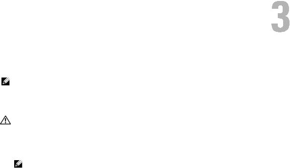
6Insert the controller gently, but firmly, until the controller is firmly seated in the PCI-E slot. See Figure 3-1.
Hardware Installation |
15 |
Figure 3-1. Installing a SAS 5/iR Adapter

 1
1
5 


 2
2
4

 3
3
1 |
bracket screw |
2 |
SAS 5/iR Adapter |
3 |
PCI-E slot |
4 |
PCI bracket |
5 |
filler bracket |
|
|
7Tighten the bracket screw, if any, or use the system’s retention clips to secure the controller to the system’s chassis.
8Connect the cables from the end devices or the backplane of the system to the controller. See Figure 3-2.
16 Hardware Installation
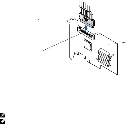
Figure 3-2. Connecting the Cable
3 
 1
1
2 
1 SAS 5/iR Adapter |
2 |
SAS x4 internal connector |
3 |
cable |
9Replace the cover of the system. See your system’s Hardware Owner’s Manual or the User’s Guide for more information on closing the system.
10Reconnect the power cable(s) and network cables, and then turn on the system.
NOTE: Ensure that you do not connect a hard disk and tape drive to the same SAS 5/iR Adapter.
NOTE: For information on connecting your SAS 5i/R controller to a tape drive see your system’s Hardware Owner’s Manual.
Hardware Installation |
|
17 |
|

18 Hardware Installation
Driver Installation
The Dell™ Serial-Attached SCSI (SAS) 5/iR controller requires software drivers to operate with Microsoft® Windows®, Red Hat® Enterprise Linux, and SUSE® Linux operating systems.
This chapter contains the procedures for installing the drivers for the following operating systems.
•Microsoft Windows 2000 Server family
•Microsoft Windows Server® 2003 Server family
•Microsoft Windows XP
•Red Hat Enterprise Linux Versions 3, 4, and 5
•SUSE Linux Enterprise Server Versions 9 and 10
•Windows Vista™
The four methods for installing a driver that are discussed in this chapter are:
•During operating system installation
•After adding a new SAS 5/iR controller on an existing operating system
•Updating existing drivers
•Installing from a Dell Precision™ workstation Operating System CD or DVD. This media includes the drivers
NOTE: Operating system installation on an Integrated Mirroring or Integrated Striping virtual disk is supported only when the virtual disk is in an optimal state.
NOTE: Device drivers are frequently updated. To ensure you have the latest version of any driver mentioned in this section, check the Dell Support website at support.dell.com. If a newer version exists, you can download the driver to your system.
Creating a Driver Diskette
NOTE: Driver diskette is not needed if you are installing from a Dell Precision Workstation Operating System CD or DVD.
1Browse to the download section of the system on the Dell Support website at support.dell.com.
2Locate and download the latest SAS 5/iR driver for the system. The drivers are packaged on the Dell Support website such that they can be written onto a diskette.
3Follow the instructions on the support site for extracting the driver to the diskette.
Driver Installation |
19 |
Loading...