


 Loading...
Dell™ PowerVault™ TL2000 Tape Library and TL4000
Tape Library
User’s Guide
Dell™ PowerVault™ TL2000 Tape Library and TL4000
Tape Library
User’s Guide
Information in this document is subject to change without notice.
© 2008 Dell Inc. All rights reserved.
Reproduction in any manner whatsoever without the written permission of Dell Inc. is strictly forbidden. Trademarks used in this text: Dell, the DELL logo and PowerVault are trademarks of Dell Inc.
Other trademarks and trade names may be used in this document to refer to either the entities claiming the marks and names or their products. Dell Inc. disclaims any proprietary interest in trademarks and trade names other than its own.
Dell PowerVault TL2000/TL4000

Read this First
Minimum Firmware Levels for Common Library Features
Table 1. Minimum Firmware Levels for common Library features
Feature |
Minimum Firmware Level(s) Required |
|
|
Dedicated Cleaning Slot removal |
Library firmware level must be greater than |
|
3.90. |
|
|
Encryption |
Library firmware level must be 5.80 or |
|
greater. |
|
LTO4 Drive firmware level must be 77BE or |
|
greater. |
|
|
Key Path Diagnostics |
Library firmware level must be greater than |
|
6.3, if feature is available. |
|
|
Path Failover |
LTO 4 Tape Drives: No minimum level of |
|
firmware is required. |
|
Library firmware must be greater than 5.80. |
|
|
IPv6 Support |
Library firmware level: 4.50 |
|
|
LT04 Drive Support |
Library firmware level: 3.90 |
|
|
Contacting Dell
For customers in the United States, call 800-WWW-DELL (800-999-3355).
Note: If you do not have an active Internet connection, you can find contact information on your purchase invoice, packing slip, bill, or Dell product catalog.
Dell provides several online and telephone-based support and service options. Availability varies by country and product, and some services may not be available in your area. To contact Dell for sales, technical support, or customer service issues:
1.Visit http://support.dell.com.
2.Verify your country or region in the Choose A Country/Region drop-down menu at the bottom of the page.
3.Click Contact Us on the left side of the page.
4.Select the appropriate service or support link based on your need.
5.Choose the method of contacting Dell that is convenient for you.
iii
iv Dell PowerVault TL2000 Tape Library and TL4000 Tape Library User's Guide

Read this First. . . . . . . . . . . |
. iii |
Basic Guidelines . . . . . . . . . . |
. |
3-1 |
||
Minimum Firmware Levels for Common Library |
|
|
Library Sharing . . . . . . . . . . . |
. 3-1 |
||
Features . . . . . . . . . . . . . . |
. iii |
Using Multiple Logical Libraries for Library |
|
|
||
Contacting Dell . . . . . . . . . . . . |
. iii |
Sharing . . . . . . . . . . . . . |
. |
3-2 |
||
|
|
|
Using Multiple Control Paths . . . . . . . |
. |
3-2 |
|
Figures . . . . . . . . . . . . . |
. |
vii |
Using Multiple Control Paths for Path Failover |
|
3-2 |
|
|
|
|
Library Partitioning and Element Addressing . . |
. 3-3 |
||
Tables . . . . . . . . . . . . . . . ix |
Logical Unit Number (LUN) Scanning . . . . |
. 3-6 |
||||
Host Interfaces . . . . . . . . . . . . |
. |
3-6 |
||||
|
|
|
||||
Safety and Environmental Notices . . |
. xi |
SCSI Interface . . . . . . . . . . . |
. |
3-6 |
||
SAS Interface . . . . . . . . . . . |
. |
3-8 |
||||
Danger Notice . . . . . . . . . . . |
. |
. xi |
Fibre Channel Interface . . . . . . . . |
. |
3-8 |
|
Caution Notice . . . . . . . . . . . |
. |
. xi |
|
|
|
|
Laser Safety and Compliance . . . . . . . |
. xii |
Chapter 4. Installation and |
|
|
||
Class I Laser Product . . . . . . . . . |
. xii |
Configuration . . . . . . . . . . |
. |
4-1 |
||
Performing the Safety Inspection Procedure . . |
|
. xii |
Installing Your Library . . . . . . . . . |
. |
4-1 |
|
Rack Safety . . . . . . . . . . . . . |
. xiii |
|||||
Using the Library Configuration Form . . . |
. 4-1 |
|||||
|
|
|
||||
Preface . . . . . . . . . . . . . |
. xv |
Choosing a Location . . . . . . . . . |
. |
4-1 |
||
Unpacking the Library . . . . . . . . |
. |
4-2 |
||||
Related Publications . . . . . . . . . . |
|
. xv |
||||
|
Verifying the Shipment . . . . . . . . |
. |
4-2 |
|||
Chapter 1. Product Description . . . |
. |
1-1 |
Installing the Library Foot Pads (for Desktop |
|
|
|
Installation ONLY) . . . . . . . . . . |
. |
4-3 |
||||
Front Panel . . . . . . . . . . . . . |
. |
1-1 |
Removing and Storing the Shipping Lock . . |
. |
4-4 |
|
Rear Panel . . . . . . . . . . . . . |
. |
1-3 |
Rackmounting the Library (for Rack Installation |
|
||
Internal View of Library . . . . . . . . . |
. |
1-5 |
ONLY). . . . . . . . . . . . . . |
. |
4-6 |
|
Bar Code Reader . . . . . . . . . . . |
. |
1-6 |
Connecting the Host Interface Cable . . . |
. |
4-12 |
|
Encryption . . . . . . . . . . . . . |
. |
1-6 |
Connecting a Power Cord . . . . . . . |
. |
4-13 |
|
Supported Internet Protocols . . . . . . . |
. |
1-8 |
Configuring Your Library . . . . . . . . |
. |
4-14 |
|
SNMP Messaging . . . . . . . . . . . |
. 1-8 |
Choosing Your Configuration Method . . . |
. 4-14 |
|||
Maximum Library Storage Capacity and Data |
|
|
Using Factory Defaults as Your Configuration |
|
4-15 |
|
Transfer Rate . . . . . . . . . . . . |
. |
1-8 |
Configuring Your Library using the Web User |
|
|
|
Ultrium Tape Drives . . . . . . . . . . |
. |
1-9 |
Interface . . . . . . . . . . . . . |
. |
4-15 |
|
Speed Matching . . . . . . . . . . |
. |
1-10 |
Preparing the Host . . . . . . . . . . |
. |
4-29 |
|
Channel Calibration . . . . . . . . . |
. |
1-10 |
Verifying the Connection . . . . . . . . |
. |
4-29 |
|
Power Management . . . . . . . . . |
. |
1-11 |
Cartridge Magazines. . . . . . . . . . |
. |
4-30 |
|
Media . . . . . . . . . . . . . . |
. |
1-11 |
Populating the Library with Data Cartridges |
|
4-33 |
|
Library Specifications . . . . . . . . . |
. |
1-11 |
Inserting the Cleaning Cartridge . . . . . |
. |
4-34 |
|
Product Environment . . . . . . . . . |
. |
1-13 |
Chapter 5. Operations . . . . . . . |
. |
5-1 |
|
Supported Device Drivers . . . . . . . . |
. |
1-13 |
||||
Chapter 2. User Interfaces . . . . . |
. |
2-1 |
Operator Control Panel Navigation . . . . . |
. 5-9 |
||
Operator Control Panel Menu Tree . . . . . |
. 5-10 |
|||||
Operator Control Panel . . . . . . . . . |
. |
2-1 |
Monitor Menu . . . . . . . . . . . |
. |
5-11 |
|
Operator Control Panel Philosophy . . . . |
. |
2-1 |
Control Menu . . . . . . . . . . . |
. |
5-16 |
|
Power-ON Display. . . . . . . . . . |
. |
2-2 |
Configure Menu . . . . . . . . . . |
. |
5-18 |
|
Note about the Front Panel LEDs . . . . . |
. |
2-2 |
Service Menu . . . . . . . . . . . |
. |
5-26 |
|
Input Modes . . . . . . . . . . . . |
. |
2-3 |
Web User Interface Menus . . . . . . . . |
. |
5-29 |
|
Power ON/OFF . . . . . . . . . . |
. |
2-4 |
Monitor Library Menu . . . . . . . . |
. |
5-30 |
|
Web User Interface. . . . . . . . . . . |
. |
2-4 |
Configure Library Menu . . . . . . . |
. |
5-38 |
|
Login . . . . . . . . . . . . . . |
. |
2-5 |
Manage Library Menu . . . . . . . . |
. |
5-49 |
|
System Status . . . . . . . . . . . |
. |
2-6 |
Service Library Menu . . . . . . . . |
. |
5-50 |
|
Web User Interface Help Pages . . . . . |
. 2-7 |
Import and Export Media during Normal Library |
|
|
||
Logging out of the Web User Interface . . . |
. |
2-7 |
Operation . . . . . . . . . . . . . |
. |
5-55 |
|
|
|
|
Configuring I/O Stations and Reserving Slots . |
. 5-57 |
||
Chapter 3. Installation Planning. . . |
. |
3-1 |
Chapter 6. Using Ultrium Media . . . |
. |
6-1 |
|
Determining the Number of Logical Libraries. . |
. 3-1 |
|||||
v
Data Cartridges . . . . . . . . . . |
. |
. |
. |
6-1 |
Cartridge Compatibility . . . . . . |
. |
. |
. |
6-2 |
WORM (Write Once, Read Many). . . . |
. |
. |
. 6-2 |
|
WORM Media . . . . . . . . . |
. |
. |
. |
6-3 |
Data Security on WORM Media . . . |
. |
. |
. 6-3 |
|
WORM Media Errors . . . . . . . |
. |
. |
. 6-3 |
|
Cleaning Cartridge. . . . . . . . . |
. |
. |
. |
6-3 |
Bar Code Label . . . . . . . . . . |
. |
. |
. |
6-4 |
Guidelines for Using Bar Code Labels . |
. |
. |
. 6-5 |
|
Write-Protect Switch . . . . . . . . |
. |
. |
. |
6-5 |
Handling the Cartridges . . . . . . . |
. |
. |
. |
6-6 |
Provide Training . . . . . . . . |
. |
. |
. |
6-6 |
Ensure Proper Packaging . . . . . |
. |
. |
. |
6-6 |
Provide Proper Acclimation and Environmental Conditions . . . . . . . . . . . . . 6-7
Perform a Thorough Inspection |
. . . . . |
. 6-7 |
|
Handle the Cartridge Carefully |
. . . . . |
. |
6-8 |
Environmental and Shipping Specifications for Tape |
|
||
Cartridges . . . . . . . . |
. . . . . |
. |
6-8 |
Chapter 7. Troubleshooting . . . . |
. |
|
7-1 |
Installation Problems . . . . . . . . . |
. |
. |
7-1 |
Maintenance Problems . . . . . . . . |
. |
. |
7-2 |
Library Recovery Problem Determination . . |
. |
. 7-7 |
|
Procedures for Isolating CRU Problems . . . |
. |
. 7-8 |
|
Isolating a Power Supply Problem . . . |
. |
. 7-8 |
|
Isolating Drive Sled Problems. . . . . . |
. |
|
7-10 |
Isolating a Library Controller Card vs. Accessor |
|
|
|
Enclosure Problem . . . . . . . . . |
. |
7-11 |
|
Isolating Web User Interface Problems . . . |
. 7-11 |
||
Isolating Accessor Scanner Problems . . . |
. 7-12 |
||
Isolating Host Attachment Interface Problems |
|
|
7-12 |
Identifying a Suspect Cartridge . . . . . . |
. |
|
7-12 |
Chapter 8. Error Codes . . . . . . |
. |
|
8-1 |
Chapter 9. Service Procedures . . . |
. |
|
9-1 |
Removing Cartridges from Magazine Slots. . |
. |
. 9-1 |
|
Releasing the Magazines Manually . . . . |
. |
. 9-1 |
|
Using the ITDT Firmware Update, Dump Retrieval |
|
||
and Drive Test Tool . . . . . . . . . |
. |
. |
9-5 |
Chapter 10. Check, Adjust, Remove, |
|
|
|
and Replace . . . . . . . . . . |
. 10-1 |
||
Tools Required. . . . . . . . . . . . |
. |
|
10-1 |
Electrostatic Discharge . . . . . . . . . |
. |
|
10-1 |
Relocating Your Library. . . . . . . . . |
. |
|
10-1 |
Replacing a Tape Drive Sled . . . . . . . |
. |
|
10-3 |
Replacing a Power Supply . . . . . . . . |
. |
|
10-7 |
Replacing a Library Controller Card . . . . |
. 10-8 |
||
Replacing Cartridge Magazines . . . . . . |
. |
10-10 |
|
Replacing the Library Enclosure . . . . . |
. |
10-10 |
|
Preparing the Defective Library for
Replacement . . . . . . . . . . . . 10-10
Unpacking and Preparing the Replacement |
|
|
Library Enclosure . . . . . . . . . |
. |
10-12 |
Swapping Library Controller Cards . . . |
. 10-15 |
|
Installing Your Drive(s) in the Replacement |
|
|
Library Enclosure . . . . . . . . . |
. |
10-17 |
Swapping Cartridge Magazines. . . . . |
. 10-19 |
|
Swapping Power Supplies . . . . . . |
. 10-22 |
|
Installing the Replacement Library Enclosure |
|
10-23 |
Completing the Installation of the |
|
|
Replacement Library Enclosure . . . . . |
. 10-25 |
|
Returning the Defective Library . . . . |
. |
10-25 |
Appendix A. SCSI Element Types and Addresses. . . . . . . . . . . . . A-1
2U |
Library I/O Slot, Storage Slots and Drive Slot |
|
Element Addresses and Physical Locations . . |
. A-1 |
|
4U |
Library I/O Slots, Storage Slots, and Drive |
|
Slots Element Addresses and Physical Locations |
. A-2 |
|
Library Partitioning and Element Addressing . |
. A-2 |
|
Appendix B. TapeAlert Flags . . . . |
. B-1 |
TapeAlert Flags Supported by the Library . . . |
. B-1 |
TapeAlert Flags Supported by the Drive . . . |
. B-3 |
Appendix C. Sense Data. . . . . . |
. C-1 |
Library Sense Data . . . . . . . . . . |
. C-1 |
Drive Sense Data . . . . . . . . . . . |
. C-6 |
Appendix D. Enabling LUN Support in Linux . . . . . . . . . . . . . . . D-1
Red Hat Enterprise Linux . . . . . . . . . D-2 Enabling LUN Support in Netware . . . . . . D-2
Appendix E. Notes on IPv6 Compatibility with Windows 2003/XP
and 2008/Vista . . . . . . . . . . . E-1
Notes on IPv6 Compatibility with Linux . . . . E-2
Appendix F. Library Configuration
Form . . . . . . . . . . . . . . . F-1
Notices . . . . . . . . . . . . . . G-1
Trademarks . . . . . . . . . . . . . . G-1
Glossary . . . . . . . . . . . . . H-1 Index . . . . . . . . . . . . . . . X-1
vi Dell PowerVault TL2000 Tape Library and TL4000 Tape Library User's Guide

Figures
1-1. |
Front panel of a 2U library . . . . . |
. |
1-1 |
1-2. |
Front panel of a 4U library . . . . . |
. |
1-2 |
1-3. |
Rear panel of a 2U library with a SCSI drive |
1-3 |
|
1-4. |
Rear panel of a 4U library with Full height |
|
|
|
Fibre Channel drive and Half height SCSI |
|
|
|
and SAS drives . . . . . . . . . |
. |
1-4 |
1-5. |
Rear panel of a 2U library with a full height |
|
|
|
dual port SAS drive . . . . . . . . |
. |
1-4 |
1-6. |
Internal view of the library . . . . . |
. |
1-5 |
1-7. |
Library drive sled without ESD springs |
|
|
|
(SCSI sled shown) . . . . . . . . |
. |
1-10 |
1-8. |
Library drive sled with ESD springs [1] |
|
|
|
(SAS sled shown) . . . . . . . . |
. |
1-10 |
2-1. |
Power-ON Screens . . . . . . . . |
. |
2-2 |
2-2. |
Web User Interface login page . . . . |
. |
2-6 |
2-3. |
2U library System Status screen . . . . |
. |
2-6 |
2-4. |
4U library System Status screen . . . . |
. |
2-6 |
2-5. |
4U library System Status screen showing a |
|
|
|
power supply failure . . . . . . . |
. |
2-7 |
3-1. |
Configuration of a One Partition System |
|
3-4 |
3-2. |
Configuration of a Two Partition System |
|
3-4 |
3-3. |
Configuration of a Three Partition System |
|
3-4 |
3-4. |
Configuration of a Four Partition System |
|
3-5 |
3-5. |
Examples of SCSI Element Addressing |
|
3-5 |
4-1. |
Removing the plastic protective sheets from |
|
|
|
the library . . . . . . . . . . . |
. |
4-2 |
4-2. |
Installing foot pads on the bottom of the |
|
|
|
library enclosure . . . . . . . . . |
. |
4-4 |
4-3. |
Shipping lock and label . . . . . . |
. |
4-5 |
4-4. |
Removing the Shipping lock and label |
|
4-5 |
4-5. |
Library shipping lock and label storage |
|
|
|
location on rear panel of library . . . . |
. |
4-6 |
4-6. |
Rack Kit Mounting hardware. . . . . |
. 4-7 |
|
4-7. |
Examples of EIA units for round hole and |
|
|
|
square hole installations . . . . . . |
. |
4-8 |
4-8. |
Rear view of a rack showing the narrow |
|
|
|
part of the rail. . . . . . . . . . |
. |
4-8 |
4-9. |
Front view of a rack showing the rails |
|
|
|
installed . . . . . . . . . . . . |
. |
4-9 |
4-10. |
2U library side screws to remove . . . |
. 4-9 |
|
4-11. |
2U library rack anchors and mounting |
|
|
|
brackets . . . . . . . . . . . . . 4-9 |
||
4-12. |
Sliding the 2U library into the rack |
|
4-10 |
4-13. |
Sliding the 4U library into the rack |
|
4-10 |
4-14. |
Securing the 2U library to the rack |
|
4-11 |
4-15. |
Securing the 4U library to the rack |
|
4-11 |
4-16. |
Attaching SCSI ([1]), Fibre Channel ([4]), |
|
|
|
and SAS ([2]) cables to the 4U library . |
. 4-12 |
|
4-17. |
Removing the protective label from the |
|
|
|
power receptacle . . . . . . . . |
. |
4-13 |
4-18. |
Log in screen on the Web User Interface |
|
4-17 |
4-19. |
The 2U library Configure Library: General |
|
|
|
screen . . . . . . . . . . . . . 4-19 |
||
4-20. |
Example: The 4U library Configure |
|
|
|
Library: General screen . . . . . . |
. |
4-20 |
4-21. |
The 4U library Configure Library: Logical |
|
|
|
Libraries page . . . . . . . . . |
. |
4-21 |
4-22. |
The Configure Library: Path Failover |
|
|
|
Feature Activation screen. . . . . . |
. |
4-21 |
4-23. |
Feature Key verification screen . . . . |
. |
4-21 |
4-24. |
Feature Activation Key screen . . . . |
. |
4-22 |
4-25. |
Configure Library: Encryption Activation |
|
|
|
screen . . . . . . . . . . . . |
. |
4-22 |
4-26. |
The Configure Library: Drive screen |
|
4-23 |
4-27. |
Configure Library: Network page |
|
4-24 |
4-28. |
Warning screen . . . . . . . . . |
. |
4-24 |
4-29. |
The Configure Library: User Access screen |
|
4-26 |
4-30. |
The Configure Library: Date and Time |
|
|
|
screen . . . . . . . . . . . . |
. |
4-27 |
4-31. |
The Configure Library: Logs and Traces |
|
|
|
screen . . . . . . . . . . . . |
. |
4-27 |
4-32. |
The Configure Library: Event Notification |
|
|
|
screen . . . . . . . . . . . . |
. |
4-28 |
4-33. |
2U library left magazine . . . . . . |
. |
4-30 |
4-34. |
2U library right magazine . . . . . |
. |
4-30 |
4-35. |
2U library I/O Station in the left magazine |
|
4-31 |
4-36. |
4U library left magazines. . . . . . |
. |
4-31 |
4-37. |
4U library right magazines . . . . . |
. |
4-32 |
4-38. |
4U library I/O Station in the lower left |
|
|
|
magazine . . . . . . . . . . . |
. |
4-32 |
4-39. |
Finger Holes on back side of 4U library |
|
|
|
I/O Station . . . . . . . . . . |
. |
4-33 |
5-1. |
2U Library Control Keys . . . . . . |
. |
5-9 |
5-2. |
4U Library Control Keys . . . . . . |
. |
5-9 |
5-3. |
Operator Control Panel Menu Tree |
|
5-11 |
5-4. |
Monitor: Library menu . . . . . . |
. |
5-12 |
5-5. |
Monitor: Drive menu . . . . . . . |
. |
5-14 |
5-6. |
Example of a 4U Monitor: Inventory menu |
|
5-15 |
5-7. |
Overview of inventoried cartridges: Lower |
|
|
|
Left Magazine of a 4U Library . . . . |
. 5-16 |
|
5-8. |
Control: I/O Station menu . . . . . |
. |
5-16 |
5-9. |
Control: Move Cartridges menu |
|
5-17 |
5-10. |
Control: Magazine menu . . . . . . |
. |
5-17 |
5-11. |
Control: Re-Inventory menu. . . . . |
. |
5-18 |
5-12. |
Configure: Logical Libraries menu |
|
5-19 |
5-13. |
Configure: Library menu . . . . . . |
. |
5-20 |
5-14. |
Configure: Drive menu . . . . . . |
. |
5-22 |
5-15. |
Configure: Network menu . . . . . |
. 5-23 |
|
5-16. |
Configure: Set Access PIN menu |
|
5-24 |
5-17. |
Configure: Restore Defaults menu |
|
5-24 |
5-18. |
Configure: Set Date and Time menu |
|
5-26 |
5-19. |
Configure: Path Failover . . . . . . |
. |
5-26 |
5-20. |
Service: Library Verify menu . . . . |
. |
5-27 |
5-21. |
Service: Run Tests menu . . . . . . |
. |
5-27 |
5-22. |
Service: Service menu . . . . . . . |
. |
5-28 |
5-23. |
Service: Display Contrast menu |
|
5-29 |
5-24. |
The 2U library Monitor Library: Library |
|
|
|
Identity page. . . . . . . . . . |
. |
5-31 |
5-25. |
The 4U library Monitor Library: Library |
|
|
|
Identity page. . . . . . . . . . |
. |
5-31 |
vii
5-26. |
The 4U library Monitor Library: Drive |
|
|
|
Identity page showing one Fibre Channel |
|
|
|
drive (#1) and one SCSI drive (#2). . . |
. 5-33 |
|
5-27. |
The 4U library Monitor Library: Library |
|
|
|
Status page . . . . . . . . . . . |
5-34 |
|
5-28. |
The 4U library Monitor Library: Drive |
|
|
|
Status page . . . . . . . . . . . |
5-36 |
|
5-29. |
The 2U library Monitor Library: Inventory |
|
|
|
page . . . . . . . . . . . . . |
5-37 |
|
5-30. |
The 4U library Monitor Library: Inventory |
|
|
|
page . . . . . . . . . . . . . |
5-38 |
|
5-31. |
The 4U library Configure Library: General |
|
|
|
and Extended page. . . . . . . . . |
5-40 |
|
5-32. |
The 4U library Configure Library: Logical |
|
|
|
Libraries page . . . . . . . . . . |
5-40 |
|
5-33. |
The 4U library Configure Library: Path |
|
|
|
Failover page . . . . . . . . . . |
5-41 |
|
5-34. |
Path Failover license verification page |
|
5-41 |
5-35. |
Feature Activation Key screen . . . . . |
5-42 |
|
5-36. |
Configure Library: Encryption Feature |
|
|
|
configuration screen . . . . . . . . |
5-42 |
|
5-37. |
The Configure Library: Drive page for a |
|
|
|
4U library . . . . . . . . . . . . |
5-44 |
|
5-38. |
Configure Library: Network page |
|
5-45 |
5-39. |
Warning screen . . . . . . . . . . |
5-45 |
|
5-40. |
Configure Library: User Access page |
|
5-47 |
5-41. |
The Configure Library: Date & Time page |
|
5-47 |
5-42. |
Configure Library: Logs & Traces page |
|
5-48 |
5-43. |
Configure Library: Event Notification page |
|
5-48 |
5-44. |
Configure Library: Restore Defaults page |
|
5-49 |
5-45. |
Manage Library: Move Media page |
|
5-49 |
5-46. |
Manage Library: Perform Inventory page |
|
5-50 |
5-47. |
Manage Library: Release Magazine page |
|
5-50 |
5-48. |
Service Library: Clean Drive page |
|
5-51 |
5-49. |
Service Library: View Logs page |
|
5-51 |
5-50. |
Service Library: View Drive Logs screen |
|
5-52 |
5-51. |
Service: Save Drive Dump . . . . . |
. 5-52 |
|
5-52. |
Service Library: Perform Diagnostics page |
|
5-53 |
5-53. |
Service Library: Perform Key Path |
|
|
|
Diagnostics page . . . . . . . . . |
5-53 |
|
5-54. |
The 2U library Service Library: Upgrade |
|
|
|
Firmware page . . . . . . . . . . |
5-54 |
|
5-55. |
The 4U library Service Library: Upgrade |
|
|
|
Firmware page . . . . . . . . . . |
5-55 |
|
5-56. |
Service Library: Reboot page . . . . . |
5-55 |
|
6-1. |
The LTO Ultrium 800 GB Data Cartridge |
|
6-1 |
6-2. |
Ultrium WORM Tape Cartridge . . . . |
. 6-3 |
|
6-3. |
Sample bar code label on the LTO Ultrium 4 |
|
|
|
Tape Cartridge . . . . . . . . . . |
6-5 |
|
6-4. |
Setting the write-protect switch . . . . . |
6-6 |
|
6-5. |
Double-boxing tape cartridges for shipping |
6-7 |
|
6-6. |
Checking for gaps in the seams of a |
|
|
|
cartridge . . . . . . . . . . . . |
6-8 |
|
7-1. |
A 250w power supply with LEDs |
|
7-8 |
7-2. |
A 80w power supply without LEDs |
|
7-9 |
9-1. |
Access holes for the left magazine |
|
9-2 |
9-2. |
Access holes for the right magazine |
|
9-3 |
9-3. |
Left Magazines pulled out of the 2U library |
9-4 |
|
9-4. |
Left Magazines pulled out of the 4U Library |
9-4 |
|
10-1. |
Shipping lock and label storage location |
|
10-2 |
10-2. |
Shipping lock and label . . . . . . |
. |
10-2 |
10-3. |
Library drive sled without ElectroStatic |
|
|
|
Discharge (ESD) springs (SCSI sled shown) |
10-3 |
|
10-4. |
Library drive sled with ESD springs [1] |
|
|
|
(SAS sled shown) . . . . . . . . |
. |
10-4 |
10-5. |
Drive sled components (full-high fibre |
|
|
|
drive in top position, half-high SCSI drive |
|
|
|
in middle position, half-high SAS drive in |
|
|
|
bottom position) on back panel of a 4U |
|
|
|
library . . . . . . . . . . . . |
. |
10-4 |
10-6. |
Pulling the drive sled out of the library |
|
|
|
(drive sled without ESD springs shown) |
. 10-5 |
|
10-7. |
Pushing the drive sled into the library |
|
|
|
(drive sled without ESD springs shown) |
. 10-6 |
|
10-8. |
Diagrams for applying conductive tape for |
|
|
|
ESD protection to the back of a drive sled |
|
|
|
installed in a 2U or 4U library . . . . |
. |
10-7 |
10-9. |
A power supply being removed from a 2U |
|
|
|
library . . . . . . . . . . . . |
. |
10-8 |
10-10. |
A Library Controller Card being removed |
|
|
|
from the library . . . . . . . . . |
. |
10-9 |
10-11. |
Rear panel of a 4U library with a Fibre |
|
|
|
Channel full height drive in the top |
|
|
|
position, a SCSI half height drive in the |
|
|
|
middle position, and a SAS half height |
|
|
|
drive in the bottom position . . . . |
. |
10-11 |
10-12. |
Removing the two mounting bracket |
|
|
|
screws anchoring the library to the rack |
|
|
|
(one screw on each side of the library . |
. 10-11 |
|
10-13. |
Foot pads installed on the bottom of the |
|
|
|
library enclosure . . . . . . . . |
. |
10-13 |
10-14. |
Removing the shipping label and lock |
|
|
|
from the top of the library and storing on |
|
|
|
the rear panel . . . . . . . . . |
. |
10-14 |
10-15. |
Library shipping lock and label storage |
|
|
|
location on the real panel of the library |
. |
10-14 |
10-16. |
Removing a Library Controller Card from |
|
|
|
the library . . . . . . . . . . |
. |
10-16 |
10-17. |
Library Front Panel LEDs . . . . . |
. |
10-17 |
10-18. |
Removing a drive sled from the library |
|
|
|
(drive sled without ESD springs shown) |
. 10-18 |
|
10-19. |
Drive sled taping diagrams . . . . |
. |
10-19 |
10-20. |
Access hole for the left magazine (facing |
|
|
|
rear of library) . . . . . . . . . |
. |
10-20 |
10-21. |
Access hole for the right magazine (facing |
|
|
|
rear of library) . . . . . . . . . |
. |
10-21 |
10-22. |
Left magazine pulled out of a 4U library |
|
|
|
(facing front of library) . . . . . . |
. |
10-22 |
10-23. |
A power supply being removed from a |
|
|
|
library . . . . . . . . . . . |
. |
10-23 |
10-24. |
Mounting brackets and anchors for |
|
|
|
securing the library in a rack (one bracket |
|
|
|
and anchor on each side of the library). . 10-24 |
||
10-25. |
Front view of a rack showing the rails |
|
|
|
installed . . . . . . . . . . . |
. |
10-24 |
A-1. |
Configuration of a One Partition System |
|
A-3 |
A-2. |
Configuration of a Two Partition System |
|
A-4 |
A-3. |
Configuration of a Three Partition System |
|
A-4 |
A-4. |
Configuration of a Four Partition System |
|
A-5 |
A-5. |
Examples of SCSI Element Addressing |
|
A-5 |
viii Dell PowerVault TL2000 Tape Library and TL4000 Tape Library User's Guide
Tables
1. |
Minimum Firmware Levels for common |
|
|
5-11. |
Drive Identity page elements . . . . |
. 5-43 |
|
|
Library features . . . . . . . . . |
|
. iii |
6-1. |
Ultrium data and cleaning cartridge |
|
|
1-1. |
2U library and 4U library front panel |
|
|
|
compatibility with Ultrium tape drive . . |
. 6-2 |
|
|
descriptions . . . . . . . . . . |
. |
1-2 |
6-2. |
Cartridges and VOLSERs compatible with |
|
|
1-2. |
2U library and 4U library rear panel |
|
|
|
the Ultrium 3 and Ultrium 4 Tape Drive . |
. 6-4 |
|
|
descriptions . . . . . . . . . . |
. |
1-4 |
6-3. |
Environment for operating, storing, and |
|
|
1-3. |
Internal view description . . . . . . |
. 1-6 |
|
shipping the LTO Ultrium Tape Cartridge |
. 6-9 |
||
1-4. |
Tape drive model and interface type |
|
1-8 |
7-1. |
Troubleshooting table . . . . . . . |
. |
7-5 |
1-5. |
Library storage capacity and data transfer |
|
|
7-2. |
Power Supply LED Meanings . . . . |
. 7-9 |
|
|
rate . . . . . . . . . . . . . |
. |
1-9 |
8-1. |
Error Codes . . . . . . . . . . |
. |
8-2 |
3-1. |
Host Drive Interface Support . . . . . |
. |
3-6 |
8-2. |
Sub error codes . . . . . . . . . |
. |
8-8 |
3-2. |
Maximum bus length between terminators |
|
3-7 |
10-1. |
. . . . . . . . . . . . . . . |
10-17 |
|
3-3. |
Recommended maximum quantity of drives |
|
A-1. |
2U library SCSI Element Types and |
|
|
|
|
per SCSI bus . . . . . . . . . . |
. |
3-7 |
|
Element Addresses . . . . . . . . |
. A-1 |
|
4-1. |
Location criteria . . . . . . . . . |
. |
4-1 |
A-2. |
4U library SCSI Element Types and |
|
|
5-1. |
Menu navigation shortcuts . . . . . |
. |
5-1 |
|
Element Addresses . . . . . . . . |
. A-1 |
|
5-2. |
Library Control Keys . . . . . . . |
. |
5-9 |
A-3. |
2U library SCSI element addresses for |
|
|
5-3. |
Factory Default Settings . . . . . . |
. |
5-25 |
|
storage slots and drive slot . . . . . |
. A-1 |
|
5-4. |
Web User Interface Menus . . . . . |
. 5-29 |
A-4. |
4U library SCSI element addresses for |
|
|
|
5-5. |
Library Identity page elements . . . . |
. |
5-30 |
|
storage slots and drive slot . . . . . |
. A-2 |
|
5-6. |
Drive Identity page elements . . . . |
. 5-31 |
B-1. |
TapeAlert Flags Supported by the Ultrium |
|
|
|
5-7. |
Library Status page elements . . . . |
. |
5-33 |
|
Tape Drive . . . . . . . . . . . |
. B-3 |
|
5-8. |
Drive Status page elements . . . . . |
. 5-34 |
C-1. |
Library Sense Keys, ASC and ASCQ |
|
C-1 |
|
5-9. |
Configure Library: General page elements |
|
5-39 |
C-2. |
LTO Tape Drive Sense Data . . . . . |
. C-6 |
|
5-10. |
Configure Library: Specific page elements |
|
5-39 |
|
|
|
|
ix
x Dell PowerVault TL2000 Tape Library and TL4000 Tape Library User's Guide
Safety and Environmental Notices
When using this product, observe the danger, caution, and attention notices that are contained in this guide. The notices are accompanied by symbols that represent the severity of the safety condition.
The sections that follow define each type of safety notice and give examples.
Danger Notice
A danger notice calls attention to a situation that is potentially lethal or extremely hazardous to people. A lightning bolt symbol always accompanies a danger notice to represent a dangerous electrical condition.
Caution Notice
A caution notice calls attention to a situation that is potentially hazardous to people because of some existing condition. A caution notice can be accompanied by one of several symbols:
If the symbol is... |
It means.... |
|
A hazardous electrical condition with less severity than electrical |
|
danger. |
|
A generally hazardous condition not represented by other safety |
|
symbols. |
32-55 kg (70.5-121.2 lbs)
A hazardous condition due to the use of a laser in the product. Laser symbols are always accompanied by the classification of the laser as defined by the U. S. Department of Health and Human Services (for example, Class I, Class II, and so forth).
A hazardous condition due to mechanical movement in or around the product.
A hazardous condition due to the weight of the unit. Weight symbols are accompanied by an approximation of the product’s weight.
svc00168
xi

Laser Safety and Compliance
Before using the library, review the following laser safety information.
Class I Laser Product
The library may contain a laser assembly that complies with the performance standards set by the U.S. Food and Drug Administration for a Class I laser product. Class I laser products do not emit hazardous laser radiation. The library has the necessary protective housing and scanning safeguards to ensure that laser radiation is inaccessible during operation or is within Class I limits. External safety agencies have reviewed the library and have obtained approvals to the latest standards as they apply.
Performing the Safety Inspection Procedure
Before you service the unit, perform the following safety inspection procedure:
1.Stop all activity between the host and the library’s tape drives.
2.Turn off the power to the library by pushing in on the Power button (1) shown in Figure 1-1 on Page 1-1 for 4 seconds.
3.If drives are SCSI attached, disconnect the SCSI cable and check the SCSI bus terminator for damage.
4.Unplug the library’s power cord or cords from the electrical outlet and the library power supply.
5.Check the library’s power cord for damage, such as a pinched, cut, or frayed cord.
6.If drives are SCSI attached, check the tape drive’s SCSI bus (signal) cable for damage.
7.If drives are FC/SAS attached, check the tape drive’s FC/SAS cable for damage.
8.Check the cover of the library for sharp edges, damage, or alterations that expose its internal parts.
9.Check the cover of the library for proper fit. It should be in place and secure.
10.Check the product label at the rear of the library to make sure that it matches the voltage at your outlet.
xii Dell PowerVault TL2000 Tape Library and TL4000 Tape Library User's Guide

Rack Safety
The following general safety information should be used for all rack mounted devices.
DANGER
vAlways lower the leveling pads on the rack cabinet.
vAlways install stabilizer brackets on the rack cabinet.
vTo avoid hazardous conditions due to uneven mechanical loading, always install the heaviest devices in the bottom of the rack cabinet. Always install servers and optional devices starting from the bottom of the rack cabinet.
vRack mounted devices are not to be used as a shelf or work space. Do not place any object on top of rack mounted devices.
vEach rack cabinet might have more than one power cord. Ensure that all power cords in the rack cabinet are disconnected before servicing any device in the rack cabinet.
vConnect all devices installed in a rack cabinet to power devices installed in the same rack cabinet. Do not plug a power cord from a device installed in one rack cabinet into a power device installed in a different rack cabinet.
vAn electrical outlet that is not correctly wired could place hazardous voltage on the metal parts of the system or the devices that attach to the system. It is the responsibility of the customer to ensure that the outlet is correctly wired and grounded to prevent an electrical shock.
CAUTION:
vDo not install a unit in a rack where the internal rack ambient temperatures will exceed the manufacturer’s recommended ambient temperature for all your rack mounted devices.
vDo not install a unit in a rack where the air flow is compromised. Ensure that air flow is not blocked or reduced on any side of the unit.
vConnect the equipment to the supply circuit such that overloading of the circuits does not compromise the supply wiring or overcurrent protection. To provide the correct power connection to a rack, refer to the rating labels located on the equipment in the rack to determine the total power requirement of the supply circuit.
v(For sliding drawers) Do not pull out or install any drawer or feature if the rack stabilizer brackets are not attached to the rack. Do not pull out more than one drawer at a time. The rack may become unstable if you pull out more than one drawer at a time.
v(For fixed drawers) Do not move a fixed drawer. Attempting to move the drawer partially or completely out of the rack may cause the rack to become unstable or cause the drawer to fall out of the rack.
Safety and Environmental Notices xiii
CAUTION:
Removing components from the upper positions in the rack cabinet improves rack stability during relocation. Follow these general guidelines whenever you relocate a populated rack cabinet within a room or building:
vReduce the weight of the rack cabinet by removing equipment starting at the top of the rack cabinet. When possible, restore the rack cabinet to the configuration of the rack cabinet as you received it. If this configuration is not known, you must do the following:
–Remove all devices in the 32U position and above.
–Ensure that the heaviest devices are installed in the bottom of the rack cabinet.
–Ensure that there are no empty U-levels between devices installed in the rack cabinet below the 32U level.
vIf the rack cabinet you are relocating is part of a suite of rack cabinets, detach the rack cabinet from the suite.
vInspect the route that you plan to take to eliminate potential hazards.
vVerify that the route that you choose can support the weight of the loaded rack cabinet. Refer to the documentation that comes with your rack cabinet for the weight of a loaded rack cabinet.
vVerify that all door openings are at least 762 x 2032 mm (30 x 80 in.).
vEnsure that all devices, shelves, drawers, doors, and cables are secure.
vEnsure that the four leveling pads are raised to their highest position.
vEnsure that there is no stabilizer bracket installed on the rack cabinet during movement.
vDo not use a ramp inclined at more than ten degrees.
vOnce the rack cabinet is in the new location, do the following:
–Lower the four leveling pads.
–Install stabilizer brackets on the rack cabinet.
–If you removed any devices from the rack cabinet, repopulate the rack cabinet from the lowest position to the highest position.
vIf a long distance relocation is required, restore the rack cabinet to the configuration of the rack cabinet as you received it. Pack the rack cabinet in the original packaging material, or equivalent. Also lower the leveling pads to raise the casters off of the pallet and bolt the rack cabinet to the pallet.
xiv Dell PowerVault TL2000 Tape Library and TL4000 Tape Library User's Guide

Preface
This manual contains information and instructions necessary for the installation, operation, and service of the Dell™ PowerVault™ TL2000 Tape Library and TL4000 Tape Library.
Related Publications
Refer to the following publications for additional information.
vGetting Started with the Dell™ PowerVault™ TL2000 and TL4000 Tape Libraries provides installation information.
vDell™ PowerVault™ TL2000 Tape Library and TL4000 Tape Library SCSI Reference provides supported SCSI commands and protocol governing the behavior of SCSI interface.
xv
xvi Dell PowerVault TL2000 Tape Library and TL4000 Tape Library User's Guide

Chapter 1. Product Description
The Dell™ PowerVault™ TL2000 Tape Library (2U library) and the Dell PowerVault TL4000 Tape Library (4U library) provide compact, high-capacity, low-cost solutions for simple, unattended data backup. The 4U library houses up to 48 tape cartridges (or 45 and an elective 3-slot I/O Station) in a compact 4U form factor with easy access to cartridges via four removable magazines. The 2U library houses up to 24 tape cartridges (or 23 and an elective 1-slot I/O Station) in a compact 2U form factor with easy access to cartridges via two removable magazines.
The TL2000/TL4000 Library supports LT03 and LT04 tape drives with these interfaces: a Small Computer Systems Interface (SCSI), Fibre Channel interface (FC), or Serial Attached SCSI interface (SAS). LTO 3 and LTO 4 Half height drives are SAS only, and LTO 4 Full height drives are SAS and Fibre Channel only. LTO3 full height drives are SCSI and Fibre Channel only.
Front Panel
3 |
1 |
2 |
3 |
a77ug173
8 |
|
4 |
|
6 |
|
7 |
|
5 |
|
4 |
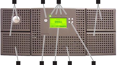
Figure 1-1. Front panel of a 2U library
1-1
3 |
1 |
2 |
3 |
a77ug172
8 6 7 4 5
Figure 1-2. Front panel of a 4U library
Table 1-1 below contains front panel descriptions for both the 2U library in
Figure 1-1 on page 1-1 and the 4U library in Figure 1-2.
Table 1-1. 2U library and 4U library front panel descriptions
Number |
Item |
Description |
|
|
|
1 |
Power button |
Pressing this button will power ON the library. Pressing and holding this button for 4 |
|
|
seconds will power OFF the unit (soft power down). No power switch or button can |
|
|
be found on the back panel of the library. |
|
|
|
2 |
Front panel |
v Ready/Activity (Green LED) - It is lit any time the unit is powered ON and able to |
|
LEDs (left to |
function. It should blink whenever there is library or drive activity, or when the |
|
right) |
|
|
library is in the process of powering up. |
|
|
|
|
|
|
v Clean Drive (Amber LED) - It will be lit when the drive needs to be cleaned. The |
|
|
LED will be turned OFF after the drive is cleaned successfully. |
|
|
v Attention (Amber LED) - It will be lit when there has been a failure that indicates a |
|
|
piece of media is bad, marginal, or invalid. It will be cleared when all invalid |
|
|
cartridges have been exported from the library. The amber LED may also be lit |
|
|
because a power supply or a power supply fan is failing, or a drive sled is defective, |
|
|
missing, or has been replaced by a different drive type. |
|
|
v Error (Amber LED) - It will be lit when there is an unrecoverable library or drive |
|
|
failure. A message is displayed at the same time on the Operator Control Panel |
|
|
display. |
|
|
|
3 |
Cartridge |
v The 2U library contains two cartridge magazines. |
|
magazines |
– The left magazine can hold up to 12 cartridges (or 11 data cartridges and the |
|
|
|
|
|
elective 1-slot I/O Station.) |
|
|
– The right magazine can hold up to 12 cartridges. |
|
|
v The 4U library contains four cartridge magazines. |
|
|
– The upper left magazine can hold up to 12 cartridges. |
|
|
– The lower left magazine can hold up to 12 cartridges (or 9 data cartridges and the |
|
|
elective 3-slot I/O Station.) |
|
|
– The upper right magazine can hold up to 12 cartridges. |
|
|
– The lower right magazine can hold up to 12 cartridges. |
|
|
|
4 |
Air vents |
These vents draw cooler air into the library enclosure and allow warm air to escape |
|
|
which helps keep the library at a normal operating temperature. |
|
|
|
1-2 Dell PowerVault TL2000 Tape Library and TL4000 Tape Library User's Guide
Table 1-1. 2U library and 4U library front panel descriptions (continued)
Number |
Item |
Description |
|
|
|
5 |
Control keys |
v UP (+) - The upper left button is used to scroll upward through menu items. |
|
|
v DOWN (-) - The lower left button is used to scroll downward through menu items. |
|
|
v CANCEL (X) - The upper right button is used to cancel a user action and return to |
|
|
the previous menu screen. |
|
|
v SELECT - The lower right button is used to display a sub-menu or force an accessor |
|
|
action. |
|
|
|
6 |
Service Tag |
This service tag links the library to your warranty. |
|
|
|
7 |
Operator |
This component is a 128 X 64 monochrome graphic display. |
|
Control Panel |
|
|
display |
|
|
|
|
8 |
I/O Station |
The Input/Output (I/O) Station is used to import and export cartridges into and out |
|
|
of the library. |
|
|
v The 2U library has an elective 1-slot I/O Station. |
|
|
v The 4U library has an elective 3-slot I/O Station. |
Rear Panel
Figure 1-3. Rear panel of a 2U library with a SCSI drive
Chapter 1. Product Description 1-3

1 |
|
2 |
|
3 |
|
4 |
a77ug100
10 |
|
9 |
|
8 |
|
7 |
|
6 |
|
5 |
Figure 1-4. Rear panel of a 4U library with Full height Fibre Channel drive and Half height SCSI and SAS drives. The configuration shown in this figure is used as an example only. This configuration is not recommended. Half height SCSI drives are not supported on the TL2000/TL4000.
1 |
|
2 |
|
3 |
|
4 |
10 |
9 |
8 |
7 |
6 |
5 |
Figure 1-5. Rear panel of a 2U library with a full height dual port SAS drive
Table 1-2. 2U library and 4U library rear panel descriptions
a77ug135
Number |
Item |
Description |
|
|
|
1 |
Power connector(s) |
Both libraries require a 110/220 volt AC power connection. |
|
|
v The 2U library has one power supply. |
|
|
v The 4U library has a minimum of one power supply, but has the capability of |
|
|
adding a redundant power supply. |
|
|
|
2 |
Host interface |
The library has one or more of the following host interface connectors on the drive |
|
connectors |
sled: |
|
|
v a 68-pin HD SCSI connector |
|
|
v a Fibre Channel connector |
|
|
v a SFF-8088 mini-SAS connector |
3 |
Tape drive sled |
This library supports the Ultrium 3 and Ultrium 4 Tape Drive. The tape drive in |
|
|
the library is packaged in a container called a drive sled. Drive sleds come in a |
|
|
Full height or Half height configuration. The drive sled is a customer replaceable |
|
|
unit (CRU), and is hot-pluggable - designed for easy removal and replacement. |
|
|
|
1-4 Dell PowerVault TL2000 Tape Library and TL4000 Tape Library User's Guide
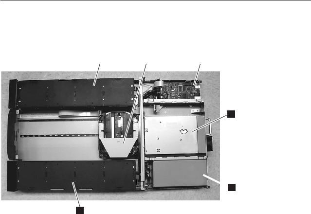
Table 1-2. 2U library and 4U library rear panel descriptions (continued)
Number |
Item |
Description |
|
|
|
4 |
Shipping lock and |
The shipping lock, which secures the accessor during shipping, and associated |
|
label storage |
label are stored on the rear panel of the library for future use. See “Removing and |
|
location |
Storing the Shipping Lock” on page 4-4. |
|
|
Attention: The shipping lock must be removed before powering ON the library |
|
|
to allow the accessor to function properly. |
|
|
|
5 |
USB port |
An alternative communication path to the library. For use by Service Personnel. |
|
|
|
6 |
Serial port |
This port is used to communicate serially with the library using an RJ-11 connector. |
|
|
For use by Service Personnel. |
|
|
|
7 |
Ethernet port |
This port is used to connect the library to a network. |
|
|
|
8 |
Tape drive LED |
This LED indicates the current status of the drive. When the LED is green, it |
|
|
indicates normal drive activity. |
|
|
|
9 |
Service Tag/Serial |
The service tag and serial number on the pull-out label links the library to your |
|
Number |
warranty. |
|
|
|
10 |
Fan vents |
These vents allow air to escape from the power supply and tape drive sled. |
|
|
|
Internal View of Library
Important: FOR REFERENCE ONLY. The customer is not authorized to remove the top cover of the library. No customer serviceable components are inside the library.
1
2 |
|
3 |
|
4 |
5
 6
6
a77ug124
Figure 1-6. Internal view of the library
Chapter 1. Product Description 1-5

Table 1-3. Internal view description
Number |
Item |
Description |
|
|
|
|
|
1 |
Right cartridge |
v In a 2U library, the right magazine can hold up to 12 cartridges. |
|
|
magazine(s) |
v In a 4U library, the right magazines can hold up to 24 cartridges. |
|
|
|
||
2 |
Left cartridge |
v In a 2U library, the left magazine can hold up to 11 cartridges and houses |
|
|
magazine(s) |
|
the elective 1-slot I/O Station. |
|
|
|
|
|
|
v In a 4U library, the left magazines can hold up to 21 cartridges and houses |
|
|
|
|
the elective 3-slot I/O Station. |
|
|
|
|
3 |
Accessor |
This component contains the library robot and bar code reader. The accessor |
|
|
|
moves cartridges to/from the following: |
|
|
|
v |
I/O Station |
|
|
v |
storage slots |
|
|
v |
tape drive(s) |
4 |
Library Controller Card |
This component is a customer replaceable unit (CRU) and stores the user |
|
|
|
configuration information or vital product data (VPD). |
|
|
|
|
|
5 |
Tape drive sled |
Both libraries support the Ultrium 3 and Ultrium 4 Tape Drive. Each tape |
|
|
|
drive in the library is packaged in a container called a drive sled. The drive |
|
|
|
sled is a customer replaceable unit (CRU), and is designed for easy removal |
|
|
|
and replacement. |
|
|
|
v The 2U library houses one full height tape drive sled or up to two half |
|
|
|
|
height tape drive sleds. |
|
|
v The 4U library houses up to two full height tape drive sleds or up to four |
|
|
|
|
half height tape drive sleds. Combinations of full height and half height |
|
|
|
drive sleds are allowed. |
|
|
|
|
6 |
Power supply |
The power supply is a customer replaceable unit (CRU) and the sole source of |
|
|
|
power for the library. The 2U has one power supply. The 4U has one or can |
|
|
|
have an optional second power supply for redundancy. |
|
|
|
|
|
Bar Code Reader
The bar code reader is an integral part of the library accessor. The bar code reader provides inventory feedback to the host application, Operator Control Panel display, and Web User Interface by reading cartridge bar code labels. The library stores the customized inventory data in memory.
Library firmware supports a 6 or 8 character volume serial number (VOLSER) on the bar code label on the tape cartridge. Bar code selection is available for libraries with library code 4.50 or greater.
Encryption
The LTO Ultrium 4 Tape Drive supports Application Managed Encryption (AME), and Library Managed Encryption (LME), using T10 encryption methods, for SAS and Fibre Channel drives only. Data encryption is supported with LTO Ultrium 4 Data Cartridges only. Encryption is also supported with library firmware version 5.80 and higher and drive firmware version 77BE and greater.
The encryption enabled drive contains the necessary hardware and firmware to encrypt and decrypt host tape application data. Encryption policy and encryption keys are provided by the host application or host server. A drive digital certificate
1-6 Dell PowerVault TL2000 Tape Library and TL4000 Tape Library User's Guide
is installed at manufacturing time. Each drive receives a unique serial number and certificate. The T10 application may validate each drive instance by checking the drive’s digital certificate.
CAUTION:
The library must be offline from any user and all media must be removed from the drives before license keys are installed or any configuration modifications are made. Please refer to “Power ON/OFF” on page 2-4 and “Removing Cartridges from Magazine Slots” on page 9-1 for instructions to take the library offline and to eject media from the drives.
To prevent possible data loss due to an EKM server failure, Dell recommends the use of a primary and secondary EKM server. This configuration provides redundancy in the event the primary EKM server is down or unavailable. Please refer to Chapter 2 (Multiple Key Managers for Redundancy) of the Dell Encryption Key Manager User’s Guide and to “Configure Library: Encryption” on page 5-41 for information on configuring a primary and secondary EKM for your library.
If the backup job fails due to an EKM server failure, the job will recover if connectivity is restored to the EKM server prior to expiration of the timeout set in the tape backup software application.
Enabling library-managed encryption on a PowerVault TL2000 or TL4000 is a 6 step process.
1.Upgrade the library and drive firmware to the latest versions. The firmware can be found at http://support.dell.com.
2.Enable library-managed encryption on the library via the license key if not already licensed. Please refer to Figure 2-25 for activation instructions. .
If you purchased library-managed encryption at the time you purchased your library, a hard copy of the license key is provided with your library as a backup. If there are any issues with the license key for library-managed encryption purchased with the library, please visit http://www.dell.com/ tapeautomation to obtain your license key. You will need the library serial number and worldwide node name to obtain the license key. Please refer to the following tables in this document for instructions on locating this information: v Table 1.2 for library serial number
v Table 4.5 for library worldwide node name
If this does not resolve your issue, please contact Dell technical support.
3.Configure library-managed encryption on your library. Please refer to Figure 2-26 for instructions.
4.Install the Dell Encryption Key Manager (EKM) application on the server designated for EKM. Please refer to Chapter 3.0 of the Dell Encryption Key Manager User’s Guide for instructions. This document can be found at http://support.dell.com.
5.Configure the EKM application. Please refer to Chapter 4.0 of the Dell Encryption Key Manager User’s Guide for instructions.
6.Start the EKM application. Please refer to Chapter 5.0 of the Dell Encryption Key Manager User’s Guide for instructions.
Note: All encryption settings should be configured or re-verified in the drive after any library or drive reset. This is because a new drive may have been added or an existing drive may have been swapped with another drive.
Chapter 1. Product Description 1-7

Supported Internet Protocols
The library supports the following Internet protocols:
vIPv4
vIPv6
To learn more about IPv4, visit http://www.iana.org/. To learn more about IPv6, visit http://www.ipv6.org/.
SNMP Messaging
Occasionally, the library may encounter a situation that you want to know about, such as an open magazine or a fault that causes the library to stop. The library provides a standard TCP/IP protocol called Simple Network Management Protocol (SNMP) to send alerts about conditions (such as need for operator intervention) over a TCP/IP LAN network to an SNMP monitoring station. These alerts are called SNMP traps. Using the information supplied in each SNMP trap, the monitoring station (together with customer-supplied software) can alert operations personnel of possible problems or operator interventions that occur.
In summary, each trap provides the following information:
vProduct Identification such as product name, description, manufacturer, model number, firmware level, and the URL that the trap is designated for.
vProduct Status such as the severity of the trap, status (current and previous) and the time the trap occurred.
vLibrary State (physical device status) such as identification and status of devices that are monitored. In the case of the library, it would include enclosure, power supply, controller, magazine status, drive count, cartridge slot count, and I/O station count. Also included would be certain library statistics, and where appropriate, the fault FSC (fault symptom code) including the severity and description of that fault.
vDrive Status such as the identification of each drive in the library, firmware level, serial number and other address and status information.
vTrap Definitions such as library status change, open magazine, I/O accessed, hard fault information, drive cleaning requests, excessive retries and library returning to normal operations.
Maximum Library Storage Capacity and Data Transfer Rate
Maximum library storage capacity and maximum data transfer rates are as follows:
Table 1-4. Tape drive model and interface type
Tape Drive Model |
Host Interface |
||
|
|
|
|
Ultrium 4 |
Full height drives |
v 4 Gb/s Fibre Channel |
|
|
|
v 3 |
Gb/s Serial Attached SCSI (SAS) - dual port |
Ultrium 4 |
Half height drives |
v 3 |
Gb/s SAS - single port |
Ultrium 3 |
Full height drives |
v Ultra160 SCSI LVD (depending on drive; single-ended (SE) is not |
|
|
|
recommended as it will severely degrade performance) |
|
|
|
v 4 |
Gb/s Fibre Channel |
Ultrium 3 |
Half height drives |
v 3 |
Gb/s SAS - single port |
1-8 Dell PowerVault TL2000 Tape Library and TL4000 Tape Library User's Guide

Table 1-5. Library storage capacity and data transfer rate
Characteristic |
2U Library Specification |
|
4U Library Specification |
||
|
|
|
|
|
|
Maximum storage capacity - |
v |
24 data cartridges |
|
v |
48 data cartridges |
Ultrium 4 Data Cartridges |
v |
Native: 19.2 TB |
|
v |
Native: 38.4 TB |
|
|
||||
|
v Compressed: 38.4 TB (2:1 |
|
v |
Compressed: 75.2 TB (2:1 |
|
|
|
compression) |
|
|
compression) |
|
|
|
|
|
|
Maximum storage capacity - |
v |
24 data cartridges |
|
v |
48 data cartridges |
Ultrium 3 Data Cartridges |
v |
Native: 9.6 TB |
|
v |
Native: 19.2 TB |
|
|
||||
|
v Compressed: 19.2 TB (2:1 |
|
v |
Compressed: 38.4 TB (2:1 |
|
|
|
compression) |
|
|
compression) |
|
|
|
|
|
|
Maximum data transfer rate |
|
|
LTO 3 HH: Native: 60 MBs |
||
|
|
LTO 3 FH: Native: 80 MBs (288 GB/hr.) |
|||
|
|
Compressed: 160 MBs (576 GB/hr.) (2:1 compression) |
|||
|
|
LTO 4 HH and FH: Native: 120 MBs |
|||
|
|
Compressed: 240 MBs (2:1 compression) |
|||
|
|
|
|
|
|
Ultrium Tape Drives
This library supports the Ultrium 3 and Ultrium 4 Tape Drives. Each tape drive in the library is packaged in a container called a drive sled. The drive sled is a customer replaceable unit (CRU), and is designed for quick removal and replacement in the library.
The Ultrium 4 Full height Tape Drives support SAS, or Fibre Channel interfaces. It features two SFF-8088 SAS connectors, or one LC Fibre Channel connector. The Ultrium 4 Half height Tape Drive supports one SAS SFF-8088 connector.
The Ultrium 3 Full height Tape Drive supports LVD Ultra160, or Fibre Channel interfaces. It features two HD68 connectors or one LC Fibre Channel connector. The Ultrium 3 Half height Drive supports one SAS SFF-8088 connector.
Chapter 1. Product Description 1-9
a77ug008
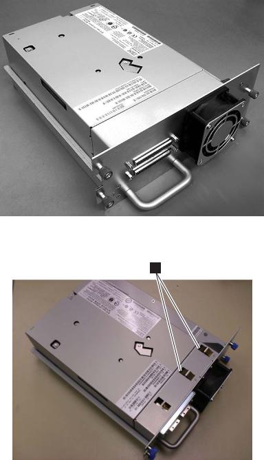
Figure 1-7. Library drive sled without ESD springs (SCSI sled shown)
1
a77ug202
Figure 1-8. Library drive sled with ESD springs [1] (SAS sled shown)
Speed Matching
To improve system performance, the Ultrium 3 and Ultrium 4 Tape Drive uses a technique called speed matching to dynamically adjust its native (uncompressed) data rate to the slower data rate of the attached server.
Channel Calibration
The channel calibration feature of the Ultrium 3 and Ultrium 4 Tape Drive customizes each read/write data channel for optimum performance. The customization enables compensation for variations in the recording channel transfer function, media characteristics, and read/write head characteristics.
1-10 Dell PowerVault TL2000 Tape Library and TL4000 Tape Library User's Guide

Power Management
The Ultrium 3 and Ultrium 4 Tape Drive’s power management function controls the drive’s electronics so that part of the electronics completely turn OFF when circuit functions are not needed for the drive’s operation.
Media
The library uses Ultrium Tape Cartridges that provide up to 800 GB native capacity (up to 1600 GB with 2:1 hardware data compression) for LTO-4 tape drives, and up to 400 GB native capacity (up to 800 GB with 2:1 hardware data compression) for LTO-3 tape drives.
Ultrium 4 tape drives can read and write LTO Ultrium 3 Data Cartridges at original Ultrium 3 capacities, and can also read LTO Ultrium 2 Data Cartridges with improved data rates. Ultrium 3 Tape Drives can read and write LTO Ultrium 2 Data Cartridges at original Ultrium 2 capacities, and can also read LTO Ultrium 1 Data Cartridges with improved data rates of up to 20 MB/second native data transfer rate (40 MB/second with 2:1 compression). Ultrium 4 tape drives cannot read Ultrium 1 tapes.
Supported cartridges include:
vLTO Ultrium 800 GB Data Cartridge (Ultrium 4)
vLTO Ultrium 400 GB Data Cartridge (Ultrium 3)
vWrite-Once-Read-Many Data Cartridge (WORM; Ultrium 3 and Ultrium 4)
vLTO Ultrium 200 GB Data Cartridge (Ultrium 2)
v100 GB Data Cartridge (Ultrium 1; read only)
vLTO Ultrium Cleaning Cartridge
For additional information, see Chapter 6, “Using Ultrium Media,” on page 6-1.
Library Specifications
Physical Specifications
Specification |
2U library |
4U library |
|
|
|
|
Rack mount 87.6 mm (3.44 in), |
Rack mount 175.2 mm (6.9 in), |
Height |
stand-alone 97.6 mm (3.84 in) |
stand-alone 185.2 mm (7.3 in) |
|
|
|
Width |
447.5 mm (17.6 in.) |
447.5 mm (17.6 in.) |
|
|
|
|
Rack mount 740 mm (29.13 in), |
Rack mount 740 mm (29.13 in), |
Depth |
stand-alone 810 mm (31.9 in) |
stand-alone 810 mm (31.9 in) |
|
|
|
Weight with 1 drive and without |
|
|
media |
15.59 kg (34.37 lbs.) |
21.32 kg (47 lbs.) |
|
|
|
Weight with media |
20.67 kg (45.57 lbs.) |
31.71 kg (69.9 lbs.) |
|
|
|
|
Power Specifications |
|
|
|
|
AC power voltage |
|
100-127 VAC; 200-240 VAC (4 - 2 A) |
|
|
|
Line frequency |
|
50-60 Hz |
|
|
|
Chapter 1. Product Description 1-11

Operation Specifications
Library with |
2U Library |
4U Library |
|
Ultrium 4 drive(s) |
|||
|
|
||
|
|
|
|
Maximum storage |
Maximum number of data cartridges: 24 |
Maximum number of data cartridges: 48 |
|
Native: 19.2 TB |
Native: 38.4 TB |
||
capacity |
|||
Compressed: 38.4 TB (2:1 compression) |
Compressed: 75.2 TB (2:1 compression) |
||
|
|||
|
|
|
|
Number of slots |
24 (including I/O Station) |
48 (Including 3 I/O station slots) |
|
|
|
|
|
Maximum data |
|
|
|
transfer rate |
|
|
|
(maximum |
Native(FH/HH Drives): 120 MBs |
||
sustained with |
|||
Compressed: 240 MBs (2:1 compression) |
|||
optimally |
|||
|
|
||
compressible data - |
|
|
|
MB/sec) |
|
|
|
|
|
|
|
Drive types |
Ultrium 4 Full height drive |
||
Fibre Channel, SAS |
|||
|
|||
|
Ultrium 4 Half height Drive: SAS |
||
|
|
|
|
Interfaces |
4 Gb/s Fibre Channel |
||
|
|||
|
3 Gb/s SAS |
||
|
|
|
|
*Host Interface Drive Transfer Rates may vary depending on host usage and interface utilization. |
|||
|
|
|
|
|
|
|
|
Library with |
2U library |
4U library |
|
Ultrium 3 drive(s) |
|||
|
|
||
|
|
|
|
Maximum storage |
Maximum number of data cartridges: 24 |
Maximum number of data cartridges: 48 |
|
Native: 9.6 TB |
Native: 19.2 TB |
||
capacity |
|||
Compressed: 19.2 TB (2:1 compression) |
Compressed: 38.4 TB (2:1 compression) |
||
|
|||
|
|
|
|
Number of slots |
24 (including I/O Station) |
48 (Including 3 I/O station slots.) |
|
|
|
|
|
|
Native for Ultrium 3 Full height: 80 MBs (288 GB/hour) |
||
Maximum data |
Compressed for Ultrium 3 Full height: 160 MBs (576 GB/hour (2:1 compression)) |
||
transfer rate |
Native for Ultrium 3 Half height: 60 MB/s |
||
|
Compressed for Ultrium 3 Half height: 120 MB/s |
||
|
|
||
|
Ultrium 3 Full height |
||
Drive types |
Drive: SCSI, Fibre Channel |
||
|
Ultrium 3 Half height Drive: Serial Attached SCSI (SAS) |
||
|
|
||
|
Ultra160 SCSI LVD |
||
Interfaces |
4 Gb/s Fibre Channel |
||
|
3 Gb/s SAS |
||
|
|
|
|
Environmental Specifications
Temperature
Operating |
10° to 35° C (50° to 95° F) |
|
|
Storage, without cartridges |
-30° to 60° C (-22° to 140° F) |
|
|
Wet bulb, operating |
26° C (79.0° F) maximum |
|
|
Temperature shock immunity - maximum rate of change |
10° C (18° F) per hour |
|
|
Miscellaneous |
|
|
|
Dust concentration |
less than 200 microgram/cubic meter |
|
|
1-12 Dell PowerVault TL2000 Tape Library and TL4000 Tape Library User's Guide
Loading...