


 Loading...
Dell PowerEdge R730 and R730xd
Owner's Manual
Regulatory Model: E31S Series
Regulatory Type: E31S001

Notes, Cautions, and Warnings
NOTE: A NOTE indicates important information that helps you make better use of your computer.
CAUTION: A CAUTION indicates either potential damage to hardware or loss of data and tells you how to avoid the problem.
WARNING: A WARNING indicates a potential for property damage, personal injury, or death.
Copyright © 2014 Dell Inc. All rights reserved. This product is protected by U.S. and international copyright and intellectual property laws. Dell™ and the Dell logo are trademarks of Dell Inc. in the United States and/or other jurisdictions. All other marks and names mentioned herein may be trademarks of their respective companies.
2014 - 09
Rev. A00
Contents |
|
1 About your system................................................................................................ |
9 |
Supported configurations..................................................................................................................... |
9 |
Front-panel features and indicators................................................................................................... |
10 |
LCD panel features.............................................................................................................................. |
16 |
Home screen.................................................................................................................................. |
17 |
Setup menu.................................................................................................................................... |
17 |
View menu..................................................................................................................................... |
18 |
Diagnostic indicators........................................................................................................................... |
18 |
Hard-drive indicator codes................................................................................................................. |
20 |
iDRAC Direct LED indicator codes...................................................................................................... |
21 |
Quick Sync indicator codes................................................................................................................ |
22 |
Back-panel features and indicators.................................................................................................... |
23 |
NIC indicator codes............................................................................................................................ |
26 |
Power indicator codes........................................................................................................................ |
26 |
Documentation matrix........................................................................................................................ |
29 |
Quick Resource Locator .............................................................................................................. |
30 |
2 Performing initial system configuration ........................................................ |
31 |
Setting up your system........................................................................................................................ |
31 |
Methods of setting up and configuring the iDRAC IP address ......................................................... |
31 |
Information about logging in to iDRAC............................................................................................. |
32 |
Methods of installing the operating system....................................................................................... |
32 |
Remote management ........................................................................................................................ |
32 |
Downloading and installing drivers and firmware............................................................................. |
32 |
3 Pre-operating system management applications........................................ |
34 |
Navigation keys................................................................................................................................... |
34 |
About System Setup............................................................................................................................ |
35 |
Entering System Setup.................................................................................................................. |
35 |
System Setup Main Menu.............................................................................................................. |
35 |
System BIOS screen...................................................................................................................... |
35 |
System Information screen details............................................................................................... |
36 |
Memory Settings screen details.................................................................................................... |
37 |
Processor Settings screen details................................................................................................. |
38 |
SATA Settings screen details......................................................................................................... |
39 |
Boot Settings screen details.......................................................................................................... |
42 |
Network Settings screen details................................................................................................... |
43 |
Integrated Devices screen details................................................................................................. |
43 |
Serial Communication screen details........................................................................................... |
45 |
System Profile Settings screen details.......................................................................................... |
45 |
System Security settings screen details........................................................................................ |
47 |
Miscellaneous Settings screen details.......................................................................................... |
49 |
About Boot Manager........................................................................................................................... |
50 |
Entering Boot Manager ................................................................................................................ |
50 |
Boot Manager main menu............................................................................................................ |
50 |
Changing the boot order.................................................................................................................... |
50 |
Choosing the system boot mode....................................................................................................... |
51 |
Assigning a system and setup password............................................................................................ |
51 |
Deleting or changing an existing system and/or setup password.................................................... |
52 |
4 Installing and removing system components............................................... |
53 |
Safety instructions............................................................................................................................... |
53 |
Before working inside your system.................................................................................................... |
53 |
After working inside your system....................................................................................................... |
53 |
Recommended tools.......................................................................................................................... |
54 |
Front bezel (optional).......................................................................................................................... |
54 |
Removing the front bezel............................................................................................................. |
54 |
Installing the front bezel............................................................................................................... |
56 |
Removing the system cover............................................................................................................... |
56 |
Installing the system cover................................................................................................................. |
57 |
Inside the system................................................................................................................................. |
58 |
Cooling shroud................................................................................................................................... |
59 |
Removing the cooling shroud...................................................................................................... |
60 |
Installing the cooling shroud........................................................................................................ |
61 |
Hard-drive tray assembly.................................................................................................................... |
61 |
Removing the hard-drive tray....................................................................................................... |
61 |
Installing the hard-drive tray......................................................................................................... |
62 |
Removing a hard-drive blank from a hard-drive carrier.............................................................. |
63 |
Installing a hard-drive blank into a hard-drive carrier................................................................. |
64 |
Removing a hard-drive carrier from the hard-drive tray............................................................. |
65 |
Installing a hard-drive carrier into the hard-drive tray................................................................ |
66 |
Removing a hard drive from a hard-drive carrier......................................................................... |
67 |
Installing a hard drive into a hard-drive carrier............................................................................ |
68 |
Removing the hard-drive backplane from the hard-drive tray................................................... |
68 |
Installing the hard-drive backplane in the hard-drive tray.......................................................... |
69 |
Cooling fans........................................................................................................................................ |
70 |
Removing a cooling fan................................................................................................................ |
70 |
Installing a cooling fan................................................................................................................... |
71 |
Cooling-fan assembly......................................................................................................................... |
72 |
Removing the cooling-fan assembly............................................................................................ |
72 |
Installing the cooling-fan assembly.............................................................................................. |
74 |
System memory.................................................................................................................................. |
74 |
General memory module installation guidelines......................................................................... |
76 |
Mode-specific guidelines.............................................................................................................. |
76 |
Sample memory configurations................................................................................................... |
78 |
Removing memory modules........................................................................................................ |
80 |
Installing memory modules.......................................................................................................... |
82 |
Processors........................................................................................................................................... |
83 |
Removing a processor.................................................................................................................. |
84 |
Installing a processor.................................................................................................................... |
88 |
PCIe card holder................................................................................................................................. |
90 |
Removing the PCIe card holder................................................................................................... |
90 |
Installing the PCIe card holder...................................................................................................... |
91 |
Opening and closing the PCIe card holder latch........................................................................ |
92 |
Cable retention bracket...................................................................................................................... |
93 |
Removing the cable retention bracket......................................................................................... |
93 |
Installing the cable retention bracket........................................................................................... |
94 |
Integrated storage controller card..................................................................................................... |
94 |
Removing the integrated storage controller card....................................................................... |
94 |
Installing the integrated storage controller card......................................................................... |
96 |
Expansion cards and expansion-card risers...................................................................................... |
96 |
Expansion card installation guidelines......................................................................................... |
96 |
Removing an expansion card from expansion-card riser 2 or 3................................................. |
98 |
Installing an expansion card into the expansion-card riser 2 or 3.............................................. |
99 |
Removing an expansion card from the expansion-card riser 1................................................ |
100 |
Installing an expansion card into the expansion-card riser 1.................................................... |
101 |
Removing the riser 1 blank.......................................................................................................... |
102 |
Installing the riser 1 blank............................................................................................................ |
103 |
Removing expansion-card risers................................................................................................ |
103 |
Installing expansion-card risers.................................................................................................. |
110 |
GPU card installation guidelines................................................................................................. |
110 |
Removing a GPU card.................................................................................................................. |
111 |
Installing a GPU card.................................................................................................................... |
112 |
Internal Dual SD Module (optional)................................................................................................... |
113 |
Removing an internal SD card..................................................................................................... |
113 |
Installing an internal SD card....................................................................................................... |
113 |
Removing the internal dual SD module ..................................................................................... |
114 |
Installing the internal dual SD module ....................................................................................... |
116 |
Network daughter card..................................................................................................................... |
116 |
Removing the network daughter card ....................................................................................... |
116 |
Installing the network daughter card.......................................................................................... |
118 |
Internal USB memory key (optional)................................................................................................. |
118 |
Replacing the internal USB key................................................................................................... |
118 |
System battery................................................................................................................................... |
119 |
Replacing the system battery...................................................................................................... |
119 |
Power supply units............................................................................................................................. |
121 |
Hot Spare feature........................................................................................................................ |
122 |
Removing the power supply unit blank...................................................................................... |
122 |
Installing the power supply unit blank........................................................................................ |
123 |
Removing an AC power supply unit........................................................................................... |
123 |
Installing an AC power supply unit............................................................................................. |
124 |
Wiring instructions for a DC power supply unit......................................................................... |
125 |
Removing a DC power supply unit............................................................................................. |
128 |
Installing a DC power supply unit............................................................................................... |
129 |
System board..................................................................................................................................... |
129 |
Removing the system board....................................................................................................... |
129 |
Installing the system board.......................................................................................................... |
131 |
Trusted Platform Module.................................................................................................................. |
133 |
Installing the Trusted Platform Module ..................................................................................... |
133 |
Re-enabling the TPM for BitLocker users.................................................................................. |
134 |
Re-enabling the TPM for TXT users............................................................................................ |
134 |
Hard drives......................................................................................................................................... |
135 |
Removing a 2.5 inch hard-drive blank........................................................................................ |
135 |
Installing a 2.5 inch hard-drive blank......................................................................................... |
136 |
Removing a 2.5 inch hard-drive blank (back)............................................................................. |
136 |
Installing a 2.5 inch hard-drive blank (back)............................................................................... |
137 |
Removing a 1.8 inch hard-drive blank........................................................................................ |
137 |
Installing a 1.8 inch hard-drive blank.......................................................................................... |
138 |
Removing a 3.5 inch hard-drive blank....................................................................................... |
138 |
Installing a 3.5 inch hard-drive blank.......................................................................................... |
139 |
Removing a 1.8 inch hard drive from a hard-drive carrier......................................................... |
139 |
Installing a 1.8 inch hard drive into a hard-drive carrier............................................................ |
140 |
Removing a hot-swap hard drive............................................................................................... |
140 |
Installing a hot-swap hard drive................................................................................................. |
142 |
Removing a hard drive from a hard-drive carrier...................................................................... |
143 |
Installing a hard drive into a hard-drive carrier.......................................................................... |
144 |
Hard-drive backplane....................................................................................................................... |
144 |
Removing the hard-drive backplane (R730).............................................................................. |
145 |
Removing the hard-drive backplane (R730xd)........................................................................... |
152 |
Installing the hard-drive backplane (R730 and R730xd)............................................................ |
163 |
Removing the optional hard-drive backplane (back)................................................................ |
163 |
Installing the optional hard-drive backplane (back).................................................................. |
164 |
Tape backup unit (optional).............................................................................................................. |
165 |
Removing the tape backup unit ................................................................................................. |
165 |
Installing the tape backup unit ................................................................................................... |
166 |
Optical drive (optional)...................................................................................................................... |
167 |
Removing the optical drive......................................................................................................... |
167 |
Installing the optical drive........................................................................................................... |
168 |
SD vFlash media card........................................................................................................................ |
168 |
Replacing an SD vFlash media card............................................................................................ |
168 |
Removing the vFlash media unit................................................................................................ |
169 |
Installing the vFlash media unit................................................................................................... |
170 |
Control panel assembly..................................................................................................................... |
171 |
Removing the control panel (R730)............................................................................................ |
171 |
Installing the control panel (R730).............................................................................................. |
174 |
Removing the control panel (R730xd)........................................................................................ |
175 |
Installing the control panel (R730xd).......................................................................................... |
176 |
Removing the I/O panel (R730xd)............................................................................................... |
177 |
Installing the I/O panel (R730xd)................................................................................................ |
178 |
5 Troubleshooting your system........................................................................ |
180 |
Safety first—for you and your system.............................................................................................. |
180 |
Troubleshooting system startup failure........................................................................................... |
180 |
Troubleshooting external connections............................................................................................ |
180 |
Troubleshooting the video subsystem............................................................................................. |
180 |
Troubleshooting a USB device......................................................................................................... |
180 |
Troubleshooting iDRAC Direct (USB XML configuration)................................................................ |
181 |
Troubleshooting iDRAC Direct (laptop connection)....................................................................... |
182 |
Troubleshooting a serial I/O device................................................................................................. |
182 |
Troubleshooting a NIC...................................................................................................................... |
182 |
Troubleshooting a wet system......................................................................................................... |
183 |
Troubleshooting a damaged system................................................................................................ |
184 |
Troubleshooting the system battery................................................................................................ |
184 |
Troubleshooting power supply units............................................................................................... |
185 |
Power source problems.............................................................................................................. |
185 |
Power supply unit problems....................................................................................................... |
185 |
Troubleshooting cooling problems................................................................................................. |
186 |
Troubleshooting cooling fans.......................................................................................................... |
186 |
Troubleshooting system memory.................................................................................................... |
187 |
Troubleshooting an internal USB key............................................................................................... |
188 |
Troubleshooting an SD card............................................................................................................. |
188 |
Troubleshooting an optical drive..................................................................................................... |
189 |
Troubleshooting a tape backup unit................................................................................................ |
189 |
Troubleshooting a hard drive........................................................................................................... |
190 |
Troubleshooting a storage controller............................................................................................... |
191 |
Troubleshooting expansion cards.................................................................................................... |
191 |
Troubleshooting processors............................................................................................................. |
192 |
System messages.............................................................................................................................. |
193 |
Warning messages....................................................................................................................... |
193 |
Diagnostic messages................................................................................................................... |
193 |
Alert messages............................................................................................................................. |
193 |
6 Using system diagnostics................................................................................ |
194 |
Dell Embedded System Diagnostics................................................................................................. |
194 |
When to use the Embedded System Diagnostics...................................................................... |
194 |
Running the Embedded System Diagnostics from Boot Manager........................................... |
194 |
Running the Embedded System Diagnostics from the Dell Lifecycle Controller.................... |
194 |
System diagnostic controls......................................................................................................... |
195 |
7 Jumpers and connectors................................................................................ |
196 |
System board jumper settings.......................................................................................................... |
196 |
System board connectors................................................................................................................. |
197 |
Disabling a forgotten password........................................................................................................ |
199 |
8 Technical specifications................................................................................. |
200 |
9 Getting help....................................................................................................... |
207 |
Contacting Dell................................................................................................................................. |
207 |
Locating your system service tag..................................................................................................... |
207 |
Documentation feedback................................................................................................................. |
207 |
Quick Resource Locator .................................................................................................................. |
207 |

1
About your system
The Dell PowerEdge R730 and R730xd systems are rack servers that support up to two Intel Xeon E5-2600 v3 processors, up to 24 DIMMs, and 28 hard drives/SSDs.
NOTE: The R730 and R730xd systems support only internal, hot-swappable hard drives.
Supported configurations
PowerEdge R730 |
Configurations |
Systems |
|
|
|
Eight-hard-drive systems |
Up to eight 3.5 inch hard drives or 2.5 inch hard drives. |
Sixteen-hard-drive |
Up to sixteen 2.5 inch hard drives. |
systems |
|
|
|
PowerEdge R730xd |
Configurations |
Systems |
|
|
|
Twelve plus two–hard- |
Up to twelve 3.5 inch hard drives and two optional 2.5 inch back-accessible |
drive systems |
hard drives. |
Sixteen plus two-hard- |
Up to twelve 3.5 inch hard drives, two optional 2.5 inch back-accessible hard |
drive systems |
drives and four 3.5 inch hard drives in the middle hard-drive tray. |
Twenty-four plus two– |
Up to twenty-four 2.5 inch hard drives and two optional 2.5 inch back |
hard-drive systems |
accessible hard drives. |
|
Up to twenty 2.5 inch hard drives, up to four 2.5 inch Dell PowerEdge |
|
Express Flash devices (PCIe SSD) and up to two optional 2.5 inch back- |
|
accessible hard drives. |
Twenty-six plus two– |
Up to eighteen 1.8 inch hard drives, up to eight 3.5 inch hard drives and up to |
hard-drive systems |
two 2.5 inch back-accessible, hard drives. |
9

Front-panel features and indicators
Figure 1. Front-panel features and indicators (3.5 inch hard-drive chassis)—PowerEdge R730
Item |
Indicator, button, or |
Icon |
Description |
|
connector |
|
|
|
|
|
|
1 |
Power-on indicator, |
|
The power-on indicator lights when the system |
|
power button |
|
power is on. The power button controls the power |
|
|
|
supply output to the system. |
|
|
|
NOTE: On ACPI-compliant operating systems, |
|
|
|
turning off the system using the power button |
|
|
|
causes the system to perform a graceful |
|
|
|
shutdown before power to the system is |
|
|
|
turned off. |
2 |
NMI button |
|
Used to troubleshoot software and device driver |
|
|
|
errors when running certain operating systems. This |
|
|
|
button can be pressed using the end of a paper clip. |
|
|
|
Use this button only if directed to do so by qualified |
|
|
|
support personnel or by the operating system |
|
|
|
documentation. |
3 |
System identification |
|
The identification buttons on the front and back |
|
button |
|
panels can be used to locate a particular system |
|
|
|
within a rack. When one of these buttons is pressed, |
|
|
|
the LCD panel on the front and the system status |
|
|
|
indicator on the back flashes until one of the |
|
|
|
buttons is pressed again. |
|
|
|
Press to toggle the system ID on and off. |
If the system stops responding during POST, press and hold the system ID button for more than five seconds to enter BIOS progress mode.
10
Item |
Indicator, button, or |
Icon |
Description |
|
connector |
|
|
|
|
|
|
|
|
|
To reset iDRAC (if not disabled in F2 iDRAC setup) |
|
|
|
press and hold the button for more than 15 |
|
|
|
seconds. |
4 |
Video connector |
|
Allows you to connect a VGA display to the system. |
5 |
LCD menu buttons |
|
Allow you to navigate the control panel LCD menu. |
6 |
Information tag |
|
A slide-out label panel which allows you to record |
|
|
|
system information such as Service Tag, NIC, MAC |
|
|
|
address and so on as per your need. |
7 |
LCD panel |
|
Displays system ID, status information, and system |
|
|
|
error messages. The LCD lights blue during normal |
|
|
|
system operation. The LCD lights amber when the |
|
|
|
system needs attention, and the LCD panel displays |
|
|
|
an error code followed by descriptive text. |
|
|
|
NOTE: If the system is connected to a power |
|
|
|
source and an error is detected, the LCD lights |
|
|
|
amber regardless of whether the system is |
|
|
|
turned on or off. |
8 |
Hard drives |
|
Up to eight 3.5 inch hot-swappable drives. |
9 |
USB management port/ |
|
Allows you to connect USB devices to the system |
|
iDRAC Direct |
|
or provides access to the iDRAC Direct features. For |
|
|
more information, see the Integrated Dell Remote |
|
|
|
|
|
|
|
|
Access Controller User’s Guide at dell.com/ |
|
|
|
esmmanuals. The USB management port is USB |
|
|
|
2.0-compliant. |
10 |
vFlash media card slot |
|
Allows you to insert a vFlash media card. |
11 |
USB connector |
|
Allows you to connect USB devices to the system. |
|
|
|
The ports are USB 2.0-compliant. |
12Optical drive (optional)
13Quick Sync (optional)
One optional SATA DVD-ROM drive or DVD+/-RW drive.
Indicates a Quick Sync enabled system. The Quick Sync feature is optional and requires a Quick Sync bezel. This feature allows management of the system using mobile devices. This feature aggregates hardware/firmware inventory and various system level diagnostic/error information that can be used in troubleshooting the system. For more information, see the Integrated Dell Remote Access Controller User’s Guide at dell.com/ esmmanuals.
11
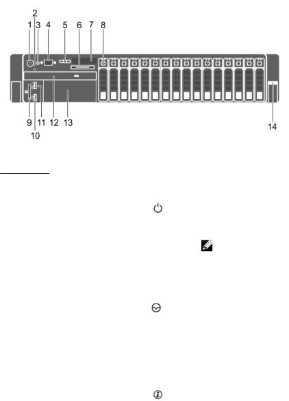
Figure 2. Front-panel features and indicators (2.5 inch hard-drive chassis)—PowerEdge R730
Item |
Indicator, button, or |
Icon |
Description |
|
connector |
|
|
|
|
|
|
1 |
Power-on indicator, |
|
The power-on indicator lights when the system |
|
power button |
|
power is on. The power button controls the power |
|
|
|
supply output to the system. |
|
|
|
NOTE: On ACPI-compliant operating systems, |
|
|
|
turning off the system using the power button |
|
|
|
causes the system to perform a graceful |
|
|
|
shutdown before power to the system is |
|
|
|
turned off. |
2 |
NMI button |
|
Used to troubleshoot software and device driver |
|
|
|
errors when running certain operating systems. |
|
|
|
This button can be pressed using the end of a |
|
|
|
paper clip. |
|
|
|
Use this button only if directed to do so by |
|
|
|
qualified support personnel or by the operating |
|
|
|
system documentation. |
3 |
System identification |
|
The identification buttons on the front and back |
|
button |
|
panels can be used to locate a particular system |
|
|
|
within a rack. When one of these buttons is |
|
|
|
pressed, the LCD panel on the front and the |
|
|
|
system status indicator on the back flashes until |
|
|
|
one of the buttons is pressed again. |
|
|
|
Press to toggle the system ID on and off. |
If the system stops responding during POST, press and hold the system ID button for more than five seconds to enter BIOS progress mode.
To reset iDRAC (if not disabled in F2 iDRAC setup) press and hold the button for more than 15 seconds.
12
Item |
Indicator, button, or |
Icon |
Description |
|
connector |
|
|
|
|
|
|
4 |
Video connector |
|
Allows you to connect a VGA display to the |
|
|
|
system. |
5 |
LCD menu buttons |
|
Allow you to navigate the control panel LCD |
|
|
|
menu. |
6 |
Information tag |
|
A slide-out label panel which allows you to record |
|
|
|
system information such as Service Tag, NIC, MAC |
|
|
|
address and so on as per your need. |
7 |
LCD panel |
|
Displays system ID, status information, and system |
|
|
|
error messages. The LCD lights blue during normal |
|
|
|
system operation. The LCD lights amber when the |
|
|
|
system needs attention, and the LCD panel |
|
|
|
displays an error code followed by descriptive text. |
|
|
|
NOTE: If the system is connected to a power |
|
|
|
source and an error is detected, the LCD lights |
|
|
|
amber regardless of whether the system is |
|
|
|
turned on or off. |
8 |
Hard drives |
|
Up to sixteen 2.5 inch hot-swappable hard drives. |
9 |
vFlash media card slot |
|
Allows you to insert a vFlash media card. |
10 |
USB connector |
|
Allows you to connect USB devices to the system. |
|
|
|
The ports are USB 2.0-compliant. |
11USB management port/ iDRAC Direct
Allows you to connect USB devices to the system or provides access to the iDRAC Direct features. For more information, see the Integrated Dell Remote Access Controller User’s Guide at dell.com/esmmanuals. The USB management port is USB 2.0-compliant.
12 |
Optical drive (optional) |
One optional SATA DVD-ROM drive or DVD+/-RW |
|
|
drive. |
13Tape drive slot (optional)
14Quick Sync (optional)
One optional 3.5 inch tape backup unit.
Indicates a Quick Sync enabled system. The Quick Sync feature is optional and requires a Quick Sync bezel. This feature allows management of the system using mobile devices. This feature aggregates hardware/firmware inventory and various system level diagnostic/error information that can be used in troubleshooting the system. For more information, see the Integrated Dell Remote Access Controller User’s Guide at dell.com/esmmanuals.
13

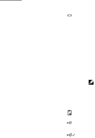
Figure 3. Front-panel features and indicators (2.5 inch hard-drive chassis)—PowerEdge R730xd
Figure 4. Front-panel features and indicators (3.5 inch hard-drive chassis)—PowerEdge R730xd
Figure 5. Front-panel features and indicators (3.5 inch and 1.8 inch hard-drive chassis)—PowerEdge R730xd
14
Item |
Indicator, Button, or |
Icon |
Description |
|
|
Connector |
|
|
|
|
|
|
|
|
1 |
Diagnostic indicators |
|
The diagnostic indicators light up to display error |
|
|
|
|
status. |
|
2 |
System identification |
|
The identification buttons on the front and back |
|
|
button |
|
panels can be used to locate a particular system |
|
|
|
|
within a rack. When one of these buttons is |
|
|
|
|
pressed, the system status indicator on the back |
|
|
|
|
flashes until one of the buttons is pressed again. |
|
|
|
|
Press to toggle the system ID on and off. |
|
|
|
|
If the system stops responding during POST, press |
|
|
|
|
and hold the system ID button for more than five |
|
|
|
|
seconds to enter BIOS progress mode. |
|
|
|
|
To reset the iDRAC (if not disabled in F2 iDRAC |
|
|
|
|
setup) press and hold the button for more than 15 |
|
|
|
|
seconds. |
|
3 |
Power-on indicator, |
|
The power-on indicator lights when the system |
|
|
power button |
|
power is on. The power button controls the power |
|
|
|
|
supply output to the system. |
|
|
|
|
NOTE: On ACPI-compliant operating systems, |
|
|
|
|
turning off the system using the power button |
|
|
|
|
causes the system to perform a graceful |
|
|
|
|
shutdown before power to the system is |
|
|
|
|
turned off. |
|
4 |
NMI button |
|
Used to troubleshoot software and device driver |
|
|
|
|
errors when running certain operating systems. |
|
|
|
|
This button can be pressed using the end of a |
|
|
|
|
paper clip. |
|
|
|
|
Use this button only if directed to do so by |
|
|
|
|
qualified support personnel or by the operating |
|
|
|
|
system's documentation. |
|
5 |
Information tag |
|
A slide-out label panel which allows you to record |
|
|
|
|
system information such as Service Tag, NIC, MAC |
|
|
|
|
address, and so on as per your need. |
|
6 |
Hard drives |
|
2.5 inch hard |
Up to twenty four 2.5 inch |
|
|
|
||
|
|
|
drive systems |
hot-swappable hard drives. |
|
|
|
3.5 inch hard |
Up to twelve 3.5 inch hot- |
|
|
|
drive systems |
swappable hard drives. |
|
|
|
3.5 inch and 1.8 |
Up to eight 3.5 inch and |
|
|
|
inch hard drive |
eighteen 1.8 inch hot- |
|
|
|
systems |
swappable hard drives. |
15
Item |
Indicator, Button, or |
Icon |
Description |
|
Connector |
|
|
|
|
|
|
7 |
USB management port/ |
|
Allows you to connect USB devices to the system |
|
iDRAC Direct |
|
or provides access to the iDRAC Direct features. |
|
|
For more information, see the Integrated Dell |
|
|
|
|
|
|
|
|
Remote Access Controller User’s Guide at |
|
|
|
dell.com/esmmanuals. The USB management port |
|
|
|
is USB 2.0-compliant. |
8 |
iDRAC Direct LED |
|
The indicator lights up to display error status. |
|
indicator |
|
|
9Video connector
10Quick Sync (optional)
Allows you to connect a VGA display to the system.
Indicates a Quick Sync enabled system. The Quick Sync feature is optional and requires a Quick Sync bezel. This feature allows management of the system using mobile devices. This feature aggregates hardware/firmware inventory and various system level diagnostic/error information that can be used in troubleshooting the system. For more information, see the Integrated Dell Remote Access Controller User’s Guide at dell.com/esmmanuals.
LCD panel features
NOTE: The LCD panel is present only on PowerEdge R730.
The LCD panel of your system provides system information and status and error messages to indicate if the system is operating correctly or if the system needs attention. For more information on error messages, see the Dell Event and Error Messages Reference Guide at dell.com/esmmanuals.
•The LCD backlight lights blue during normal operating conditions and lights amber to indicate an error condition.
•The LCD backlight is off when the system is in standby mode and can be turned on by pressing either the Select, Left, or Right button on the LCD panel.
•The LCD backlight remains off if LCD messaging is turned off through the iDRAC utility, the LCD panel, or other tools.
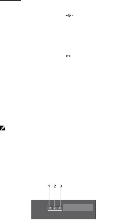
Figure 6. LCD panel features
16

Item |
Button |
Description |
|
|
|
1 |
Left |
Moves the cursor back in one-step increments. |
2 |
Select |
Selects the menu item highlighted by the cursor. |
3 |
Right |
Moves the cursor forward in one-step increments. |
|
|
During message scrolling: |
|
|
• Press and hold the button to increase scrolling speed. |
|
|
• Release the button to stop. |
NOTE: The display will stop scrolling when the button is released. After 45 seconds of inactivity the display will start scrolling.
Home screen
The Home screen displays user-configurable information about the system. This screen is displayed during normal system operation when there are no status messages or errors. When the system is in standby mode, the LCD backlight turns off after five minutes of inactivity if there are no error messages. Press one of the three navigation buttons (Select, Left, or Right) to view the Home screen.
To navigate to the Home screen from another menu, continue to select the up arrow  until the Home icon
  is displayed, and then select the Home icon.
From the Home screen, press the Select button to enter the main menu.
Setup menu
NOTE: When you select an option in the Setup menu, you must confirm the option before proceeding to the next action.
Option |
Description |
iDRAC |
Select DHCP or Static IP to configure the network mode. If Static IP is selected, |
|
the available fields are IP, Subnet (Sub), and Gateway (Gtw). Select Setup DNS to |
|
enable DNS and to view domain addresses. Two separate DNS entries are available. |
Set error |
Select SEL to display LCD error messages in a format that matches the IPMI |
|
description in the SEL. This is useful when trying to match an LCD message with an |
|
SEL entry. |
|
Select Simple to display LCD error messages in a simplified user-friendly |
|
description. For more information on error messages, see the Dell Event and Error |
|
Messages Reference Guide at dell.com/esmmanuals. |
Set home |
Select the default information to be displayed on the LCD Home screen. See View |
|
menu to see the options and option items that can be set as the default on the |
|
Home screen. |
17

View menu
NOTE: When you select an option in the View menu, you must confirm the option before proceeding to the next action.
Option |
Description |
iDRAC IP |
Displays the IPv4 or IPv6 addresses for iDRAC8. Addresses include DNS (Primary |
|
and Secondary), Gateway, IP, and Subnet (IPv6 does not have Subnet). |
MAC |
Displays the MAC addresses for iDRAC, iSCSI, or Network devices. |
Name |
Displays the name of the Host, Model, or User String for the system. |
Number |
Displays the Asset tag or the Service tag for the system. |
Power |
Displays the power output of the system in BTU/hr or Watts. The display format can |
|
be configured in the Set home submenu of the Setup menu. |
Temperature |
Displays the temperature of the system in Celsius or Fahrenheit. The display format |
|
can be configured in the Set home submenu of the Setup menu. |
Diagnostic indicators
The diagnostic indicators on the system front panel display error status during system startup.
NOTE: No diagnostic indicators are lit when the system is switched off. To start the system, plug it into a working power source and press the power button.
Icon |
Description |
Condition |
Corrective action |
|
|
|
|
|
Health |
If the system is on, and in |
None required. |
|
indicator |
good health, the indicator |
|
|
|
lights solid blue. |
|
The indicator blinks amber if the system is on or in standby, and if any error exists (for example, a failed fan or hard drive).
See the System Event Log or system messages for the specific issue. For more information on error messages, see the Dell Event and Error Messages Reference Guide at dell.com/esmmanuals.
Invalid memory configurations can cause the system to halt at startup without any video output. See Getting help.
Hard-drive |
The indicator blinks amber if a |
indicator |
hard drive experiences an |
|
error. |
See the System Event Log to determine the hard drive that has an error. Run the appropriate Online Diagnostics test. Restart system and run embedded diagnostics (ePSA). If the hard drives are configured in a RAID array, restart the system and enter the host adapter configuration utility program.
Electrical |
The indicator blinks amber if |
indicator |
the system experiences an |
See the System Event Log or system messages for the specific issue. If it is due to
18

Icon |
Description Condition |
Corrective action |
electrical error (for example, voltage out of range, or a failed power supply or voltage regulator).
Temperature The indicator blinks amber if indicator the system experiences a
thermal error (for example, a temperature out of range or fan failure).
Memory |
The indicator blinks amber if a |
indicator |
memory error occurs. |
a problem with the power supply, check the LED on the power supply. Re-seat the power supply by removing and reinstalling it. If the problem persists, see Getting help.
Ensure that none of the following conditions exist:
•A cooling fan is removed or has failed.
•System cover, cooling shroud, EMI filler panel, memory-module blank, or backfiller bracket is removed.
•Ambient temperature is too high.
•External airflow is obstructed.
See Getting help.
See the system event log or system messages for the location of the failed memory. Reinstall the memory device. If the problem persists, see Getting help.
PCIe |
The indicator blinks amber if a |
indicator |
PCIe card experiences an |
|
error. |
Restart the system. Update any required drivers for the PCIe card. Re-install the card. If the problem persists, see Getting help.
NOTE: For more information on supported PCIe cards, see Expansion card installation guidelines.
19
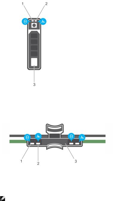
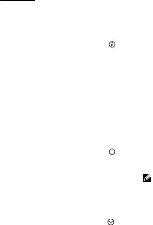
Hard-drive indicator codes
Figure 7. Hard-drive indicators
1. |
hard-drive activity indicator |
2. |
hard-drive status indicator |
3.hard drive
Figure 8. Hard-drive indicators on the hard-drive tray backplane
1. |
hard-drive activity indicator |
2. |
hard-drive status indicator |
3.hard-drive backplane on hard-drive tray
NOTE: If the hard drive is in Advanced Host Controller Interface (AHCI) mode, the status indicator (on the right side) does not function and remains off.
20
Drive-status indicator pattern (RAID only) |
Condition |
|
|
Blinks green two times per second |
Identifying drive or preparing for removal. |
Off |
Drive ready for insertion or removal. |
|
NOTE: The drive status indicator remains off until |
|
all hard drives are initialized after the system is |
|
turned on. Drives are not ready for insertion or |
|
removal during this time. |
Blinks green, amber, and turns off |
Predicted drive failure |
Blinks amber four times per second |
Drive failed |
Blinks green slowly |
Drive rebuilding |
Steady green |
Drive online |
Blinks green three seconds, amber three |
Rebuild aborted |
seconds, and turns off six seconds |
|
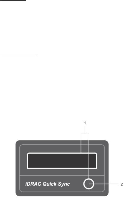
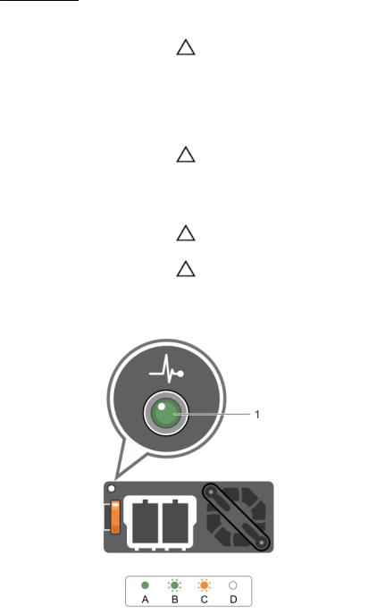
iDRAC Direct LED indicator codes
NOTE: The iDRAC Direct LED indicator does not light up for the USB mode.
Figure 9. iDRAC Direct LED indicator
1.iDRAC Direct status indicator
The table below displays iDRAC Direct activity when configuring iDRAC Direct by using the management port (USB XML Import).
Convention |
iDRAC Direct |
Condition |
|
LED indicator |
|
|
pattern |
|
|
|
|
A |
Green |
Lights green for a minimum of 2 seconds at the beginning and end |
|
|
of a file transfer. |
B |
Flashing green |
Indicates file transfer or any operation tasks. |
21
Convention |
iDRAC Direct |
Condition |
|
LED indicator |
|
|
pattern |
|
|
|
|
C |
Green and turns |
Indicates that the file transfer is complete. |
|
off |
|
D |
Not lit |
Indicates that the USB is ready to be removed or that a task is |
|
|
complete. |
The table below displays iDRAC Direct activity when configuring iDRAC Direct using your laptop and cable (Laptop Connect).
iDRAC Direct LED |
Condition |
indicator pattern |
|
|
|
Solid green for two |
Indicates that the laptop is connected. |
seconds |
|
Flashing green (on |
Indicates that the laptop connected is recognized. |
for two seconds and |
|
off for two seconds) |
|
Turns off |
Indicates that the laptop is unplugged.. |
Quick Sync indicator codes
Figure 10. Quick Sync indicator codes
1. |
Quick Sync status indicator |
2. |
Quick Sync activation button |
22
Power indicator pattern |
Condition |
|
|
Slow blink |
Quick Sync is waiting to be configured from iDRAC. |
Solid |
Quick Sync is ready to transfer. |
Blinks three times rapidly and then turns off |
Quick Sync feature is disabled from iDRAC. |
Blinks continuously when the mobile device |
Indicates data transfer activity. |
touches the antenna |
|
Blinks rapidly five times and turns off for one second when the activation button is pressed. This pattern is repeated until the activation button is pressed again.
Quick Sync hardware is not responding properly. Reseat the bezel. the problem persists, see Getting help.
Off |
Indicates that the Quick Sync feature is turned off. |
|
Use the activation button to activate it. If pressing the |
|
activation button does not turn on the LEDs, it |
|
indicates that power is not delivered to the Quick |
|
Sync bezel. |
|
NOTE: For security purposes, Quick Sync turns |
|
off after thirty seconds of in-activity after the |
|
activation button is pressed. Once timed-out, |
|
the user is expected to press the activation |
|
button again to activate Quick Sync. |
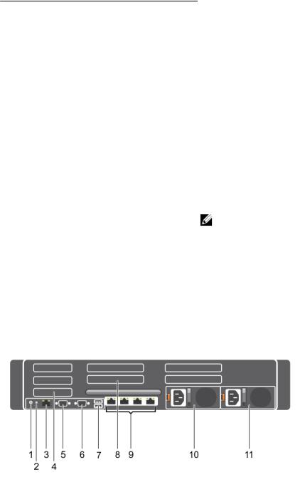
Back-panel features and indicators
Figure 11. Back-panel features and indicators—PowerEdge R730
23
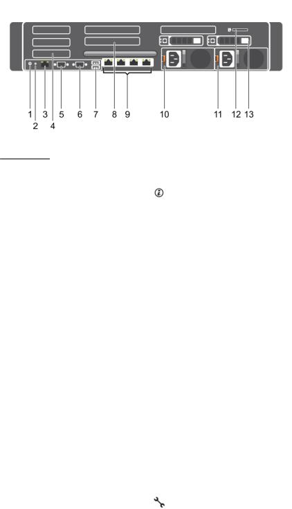
Figure 12. Back-panel features and indicators—PowerEdge R730xd
Item |
Indicator, button, or |
Icon |
Description |
|
connector |
|
|
|
|
|
|
1 |
System identification |
|
The identification buttons on the front and back |
|
button |
|
panels can be used to locate a particular system |
|
|
|
within a rack. |
PowerEdge |
When one of these buttons |
R730 |
is pressed, the LCD panel on |
|
the front and the system |
|
status indicator on the back |
|
flashes until one of the |
|
buttons is pressed again. |
PowerEdge |
When one of these buttons |
R730xd |
is pressed, the system status |
|
indicator on the back flashes |
|
until one of the buttons is |
|
pressed again. |
|
|
Press to toggle the system ID on and off. |
|
|
If the system stops responding during POST, press |
|
|
and hold the system ID button for more than five |
|
|
seconds to enter BIOS progress mode. |
|
|
To reset iDRAC (if not disabled in F2 iDRAC setup) |
|
|
press and hold the button for more than 15 |
|
|
seconds. |
2 |
System identification |
Connects the optional system status indicator |
|
connector |
assembly through the optional cable management |
|
|
arm. |
3 |
iDRAC8 Enterprise port |
Dedicated management port. |
4 |
Half-height PCIe |
Allows you to connect up to three half-height PCI |
|
expansion-card slot (3) |
Express expansion cards. |
24
Item |
Indicator, button, or |
Icon |
Description |
|
connector |
|
|
|
|
|
|
5 |
Serial connector |
|
Allows you to connect a serial device to the |
|
|
|
system. |
6 |
Video connector |
|
Allows you to connect a VGA display to the system. |
7 |
USB connector (2) |
|
Allows you to connect USB devices to the system. |
|
|
|
The ports are USB 3.0-compliant. |
8Full-height PCIe expansion-card slot (4) (PowerEdge R730)
Allows you to connect up to four full-height PCI Express expansion cards.
Full-height PCIe expansion-card slot (3) (PowerEdge R730xd)
Allows you to connect up to three full-height PCI Express expansion cards.
9 |
Ethernet connector (4) |
Four integrated 10/100/1000 Mbps NIC |
|
|
|
connectors |
|
|
|
or |
|
|
|
Four integrated connectors that include: |
|
|
|
• Two 10/100/1000 Mbps NIC connectors |
|
|
|
• Two 100 Mbps/1 Gbps/10 Gbps SFP+/10 GbE T |
|
|
|
connectors |
|
10 |
Power supply unit (PSU1) |
AC |
495 W, 750 W, or 1100 W |
|
|
||
11 |
Power supply unit |
or |
|
|
(PSU2) |
|
|
|
|
|
|
|
|
DC |
750 W or 1100 W |
12 |
vFlash media card slot |
Allows you to insert a vFlash media card. |
|
|
|
|
NOTE: This applies only to PowerEdge R730xd |
13 |
Hard drive (2) (back) |
Up to two hot-swappable 2.5 inch hard drives. |
|
|
|
|
NOTE: This applies only to PowerEdge R730xd |
25
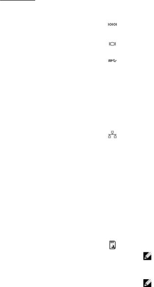
NIC indicator codes
Figure 13. NIC indicators |
|
|
|
1. |
link indicator |
2. |
activity indicator |
|
|
||
Indicator |
Indicator code |
||
|
|
||
Link and activity indicators are off |
The NIC is not connected to the network. |
||
Link indicator is green |
The NIC is connected to a valid network at its |
||
|
|
maximum port speed (1 Gbps or 10 Gbps). |
|
Link indicator is amber |
The NIC is connected to a valid network at less |
||
|
|
than its maximum port speed. |
|
Activity indicator is blinking green |
Network data is being sent or received. |
||
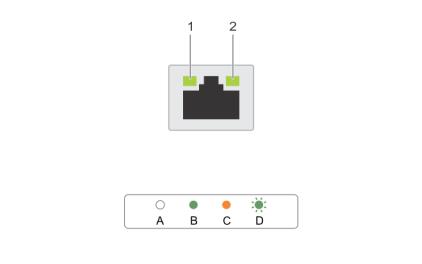
Power indicator codes
Each AC power supply unit (PSU) has an illuminated translucent handle and each DC power supply unit (when available) has an LED that serves as an indicator to show whether power is present or a power fault has occurred.
26
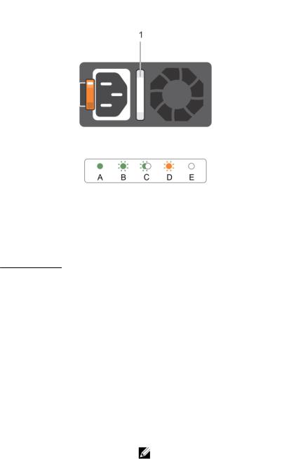
Figure 14. AC power supply unit status indicator
1.AC power supply unit status indicator/handle
Convention |
Power indicator |
Condition |
|
pattern |
|
|
|
|
A |
Green |
The handle indicator lights green indicating that a valid power |
|
|
source is connected to the power supply unit and that the power |
|
|
supply unit is operational. |
B |
Flashing green |
When updating the firmware of the power supply unit, the power |
|
|
supply unit handle flashes green. |
C |
Flashing green |
When hot-adding a power supply unit (PSU), the power supply unit |
|
and turns off |
handle flashes green five times at 4 Hz rate and turns off. This |
|
|
indicates that the power supply unit is mismatched with the other |
|
|
power supply unit (in terms of efficiency, feature set, health status, |
|
|
and supported voltage). Replace the power supply unit that has the |
|
|
flashing indicator with a power supply unit that matches the capacity |
|
|
of the other installed power supply unit. |
|
|
NOTE: For AC power supplies, use only PSUs with the Extended |
|
|
Power Performance (EPP) label on the back. Mixing PSUs from |
|
|
previous generations of servers can result in a PSU mismatch |
|
|
condition or failure to power on. |
D |
Flashing amber |
Indicates a problem with the power supply unit. |
27
Convention |
Power indicator |
Condition |
|
pattern |
|
|
|
|
|
|
CAUTION: When correcting a power supply unit mismatch, |
|
|
replace only the power supply unit with the flashing indicator. |
|
|
Swapping the opposite power supply unit to make a matched |
|
|
pair can result in an error condition and unexpected system |
|
|
shutdown. To change from a High Output configuration to a |
|
|
Low Output configuration or vice versa, you must power |
|
|
down the system. |
|
|
CAUTION: AC power supplies support both 220 V and 110 V |
|
|
input voltages with the exception of Titanium power supplies, |
|
|
which support only 220 V. When two identical power supplies |
|
|
receive different input voltages, they can output different |
|
|
wattages, and trigger a mismatch. |
|
|
CAUTION: If two power supplies are used, they must be of the |
|
|
same type and have the same maximum output power. |
|
|
CAUTION: Combining AC and DC power supplies is not |
|
|
supported and triggers a mismatch. |
E |
Not lit |
Power is not connected. |
Figure 15. DC power supply unit status indicator
1.DC power supply unit status indicator
28

Convention |
Power indicator |
Condition |
|
pattern |
|
|
|
|
A |
Green |
The handle/LED indicator lights green indicating that a valid power |
|
|
source is connected to the power supply unit and that the power |
|
|
supply unit is operational. |
B |
Flashing green |
When hot-adding a power supply unit, power supply unit LED |
|
|
flashes green. This indicates that the power supply unit is |
|
|
mismatched with the other power supply unit (in terms of |
|
|
efficiency, feature set, health status, and supported voltage). |
|
|
Replace the power supply unit that has the flashing indicator with a |
|
|
power supply unit that matches the capacity of the other installed |
|
|
power supply unit. |
C |
Flashing amber |
Indicates a problem with the power supply unit. |
|
|
CAUTION: When correcting a power supply unit mismatch, |
|
|
replace only the power supply unit with the flashing |
|
|
indicator. Swapping the opposite power supply unit to make |
|
|
a matched pair can result in an error condition and |
|
|
unexpected system shutdown. To change from a High |
|
|
Output configuration to a Low Output configuration or vice |
|
|
versa, you must power down the system. |
|
|
CAUTION: AC power supplies support both 220 V and 110 V |
|
|
input voltages with the exception of Titanium power |
|
|
supplies, which support only 220 V. When two identical |
|
|
power supplies receive different input voltages, they can |
|
|
output different wattages, and trigger a mismatch. |
|
|
CAUTION: If two power supplies are used, they must be of |
|
|
the same type and have the same maximum output power. |
|
|
CAUTION: Combining AC and DC power supplies is not |
|
|
supported and triggers a mismatch. |
D |
Not lit |
Power is not connected. |
Documentation matrix
The documentation matrix provides information on documents that you can refer to for setting up and managing your system.
To... |
Refer to... |
|
|
Install your system into a rack |
Rack documentation included with your rack |
|
solution |
Set up your system and know the system technical specifications
Install the operating system
Getting Started With Your System that shipped with your system or see dell.com/poweredgemanuals
Operating system documentation at dell.com/ operatingsystemmanuals
29
To... |
Refer to... |
|
|
Get an overview of the Dell Systems Management |
Dell OpenManage Systems Management Overview |
offerings |
Guide at dell.com/openmanagemanuals |
Configure and log in to iDRAC, set up managed |
Integrated Dell Remote Access Controller User's |
and management system, know the iDRAC |
Guide at dell.com/esmmanuals |
features and troubleshoot using iDRAC |
|
Know about the RACADM subcommands and supported RACADM interfaces
Launch, enable and disable Lifecycle Controller, know the features, use and troubleshoot Lifecycle Controller
RACADM Command Line Reference Guide for iDRAC and CMC at dell.com/esmmanuals
Dell Lifecycle Controller User’s Guide at dell.com/ esmmanuals
Use Lifecycle Controller Remote Services |
Dell Lifecycle Controller Remote Services Quick |
|
Start Guide at dell.com/esmmanuals |
Set up, use, and troubleshoot OpenManage Server Administrator
Install, use and troubleshoot OpenManage Essentials
Know the features of the storage controller cards, deploy the cards, and manage the storage subsystem
Dell OpenManage Server Administrator User’s Guide at dell.com/openmanagemanuals
Dell OpenManage Essentials User’s Guide at dell.com/openmanagemanuals
Storage controller documentation at dell.com/ storagecontrollermanuals
Check the event and error messages generated by the system firmware and agents that monitor system components
Dell Event and Error Messages Reference Guide at dell.com/esmmanuals
Quick Resource Locator
Use the Quick Resource Locator (QRL) to get immediate access to system information and how-to videos. This can be done by visiting dell.com/QRL or by using your smartphone or tablet and a model specific Quick Resource (QR) code located on your Dell PowerEdge system. To try out the QR code, scan the following image.
30
Loading...