


Dell PowerEdge C410x
Hardware Owner’s Manual

Notes, Cautions, and Warnings
NOTE: A NOTE indicates important information that helps you make better use of your computer.
 CAUTION: A CAUTION indicates potential damage to hardware or loss of data if instructions are not followed.
 WARNING: A WARNING indicates a potential for property damage, personal injury, or death.
Information in this publication is subject to change without notice. © 2010 Dell Inc. All rights reserved.
Reproduction of these materials in any manner whatsoever without the written permission of Dell Inc. is strictly forbidden.
Trademarks used in this text: Dell™, the DELL logo, and PowerEdge™ are trademarks of Dell Inc.
Other trademarks and trade names may be used in this publication to refer to either the entities claiming the marks and names or their products. Dell Inc. disclaims any proprietary interest in trademarks and trade names other than its own.
Regulatory Model B02S
July 2010 Rev. A00
I
Contents
NOTES, CAUTIONS, AND WARNINGS |
I |
||
CONTENTS |
II |
||
INTRODUCTION |
1 |
||
Checklist |
|
1 |
|
CHAPTER 1: PRODUCT OVERVIEW |
2 |
||
1.1 |
A Tour of the System |
2 |
|
1.1.1. |
System Front View |
2 |
|
1.1.2. |
System Back View |
3 |
|
1.2 |
System LEDs Description |
4 |
|
1.2.1. |
Front System LEDs |
4 |
|
1.2.2. |
LAN LEDs |
5 |
|
CHAPTER 2: REMOVING AND INSTALLING HARDWARE |
6 |
||
Safety Measures |
6 |
||
2.1. |
Dell PowerEdge C410X Middle Board Connectors and Jumpers |
7 |
|
2.2. |
System Cover |
8 |
|
2.3. |
GPGPU Cage |
9 |
|
2.4. |
Replacing GPGPU Card |
10 |
|
2.5. |
System Fans |
14 |
|
2.6. |
System Fans Cages |
16 |
|
2.7. |
Power Supplies |
18 |
|
2.8. |
Removing Power Distribution Board (PDB) |
19 |
|
2.9. |
Replacing iPass Board |
22 |
|
2.10. Replacing Middle Board |
25 |
||
2.11. Replacing Front I/O Panel |
26 |
||
2.12. Installing the Rail and the System |
28 |
||
CHAPTER 3: CABLE ROUTINGS |
30 |
||
II
iPass Port Mapping |
31 |
CHAPTER 4: BMC REMOTE MANAGEMENT CONSOLE |
32 |
Initial Configuration via DHCP Server |
32 |
Static/DHCP IP Controlled by Front Panel Button |
33 |
Remote Management Console Overview |
34 |
Enter Dell Remote Management Console |
35 |
Properties |
35 |
Configuration |
36 |
Network |
36 |
Security |
37 |
User |
38 |
Services |
39 |
IPMI |
40 |
Sessions |
42 |
Updates |
43 |
Utilities |
44 |
Server Information |
45 |
Power Control |
45 |
Power Consumption |
46 |
GPU Power Consumption |
47 |
Thermal |
48 |
Fans |
48 |
Temperatures |
48 |
System Event Log |
49 |
Platform Events |
50 |
Traps Settings |
51 |
Email Settings |
52 |
CHAPTER 5: TROUBLESHOOTING YOUR SYSTEM |
53 |
CHAPTER 6: GETTING HELP |
58 |
Contacting Dell |
58 |
INDEX |
59 |
III
Introduction
Checklist
Carefully unpack the Dell PowerEdge C410X server and check that the following items were included.
One Dell PowerEdge C410X system
Dell PowerEdge C410x Getting Started Guide
Safety, Environmental, and Regulatory Information (SERI)
Warranty and Support Information (WSI) or End User License Agreement (EULA)
Contact Dell if some items are missing or appear damaged.
1
Chapter 1: Product Overview
1.1A Tour of the System
The following sections describe the external features of the Dell PowerEdge C410X server.
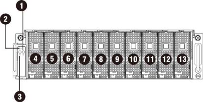
1.1.1. System Front View
|
Figure 1 – Front View |
||
|
|
|
|
1 |
System LED |
8 |
GPGPU Cage 5 |
|
|
|
|
2 |
UID LED/Button |
9 |
GPGPU Cage 6 |
|
|
|
|
3 |
Power LED/Button |
10 |
GPGPU Cage 7 |
|
|
|
|
4 |
GPGPU Cage 1 |
11 |
GPGPU Cage 8 |
|
|
|
|
5 |
GPGPU Cage 2 |
12 |
GPGPU Cage 9 |
|
|
|
|
6 |
GPGPU Cage 3 |
13 |
GPGPU Cage 10 |
|
|
|
|
7 |
GPGPU Cage 4 |
|
|
|
|
|
|
2
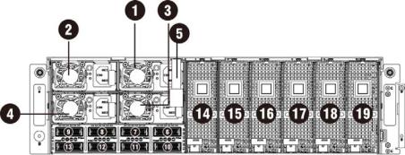
1.1.2. System Back View
Back view of system is shown below:
|
Figure 2 – Back View |
||
|
|
|
|
1 |
Power Module 1 |
11 |
iPass connector 6 |
|
|
|
|
2 |
Power Module 2 |
12 |
iPass connector 7 |
|
|
|
|
3 |
Power Module 3 |
13 |
iPass connector 8 |
|
|
|
|
4 |
Power Module 4 |
14 |
GPGPU Cage 11 |
|
|
|
|
5 |
BMC LAN Cable |
15 |
GPGPU Cage 12 |
|
|
|
|
6 |
iPass connector 1 |
16 |
GPGPU Cage 13 |
|
|
|
|
7 |
iPass connector 2 |
17 |
GPGPU Cage 14 |
|
|
|
|
8 |
iPass connector 3 |
18 |
GPGPU Cage 15 |
|
|
|
|
9 |
iPass connector 4 |
19 |
GPGPU Cage 16 |
|
|
|
|
10 |
iPass connector 5 |
|
|
|
|
|
|
3
1.2System LEDs Description
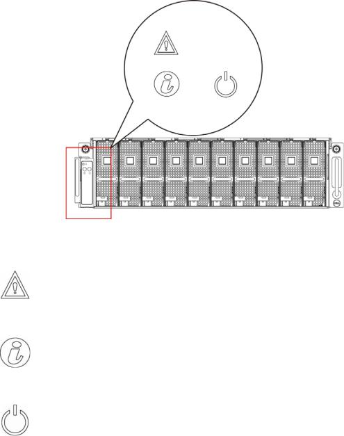
1.2.1. Front System LEDs
The front system LEDs contain Status LED, Power LED and UID LED information. The detailed LEDs information is listed below:
Figure 3 – Front System LEDs
Table 1 Front System LEDs
|
Status LED |
Displays status/errors and is controlled by BMC. |
|
||
|
|
Color |
Condition |
Occurrence |
|
|
|
Amber |
Blink Fast |
Power supply fail |
|
|
|
|
On |
FAN fail or sensor error |
|
|
|
|
|
|
|
|
|
|
Blink |
GPU card fail |
|
|
|
|
|
|
|
|
UID LED |
Lights when front or rear ID button is pressed. |
|
||
|
|
|
|
|
|
|
|
Color |
Condition |
Occurrence |
|
|
|
Blue |
Off |
No identification |
|
|
|
|
Blinking |
ID Button pressed on system (ID command |
|
|
|
|
|
executed) |
|
|
|
Lights green when server is powered on. |
|
||
|
|
|
|
|
|
|
Power LED |
Color |
|
Condition |
Occurrence |
|
|
|
On |
Power on |
|
|
|
|
|
||
|
|
Green |
|
Blinking |
Power on fail or without |
|
|
|
|
any GPU card |
|
|
|
|
|
|
|
4
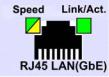
1.2.2. LAN LEDs
Figure 4 – LAN LEDs
Table 2 LAN LEDs
LAN |
LAN Link/Activity |
Color |
Condition |
Occurrence |
|
|
Green |
On |
LAN Link / no Access |
|
|
|
|
|
|
|
|
Blink |
LAN Access |
|
|
N/A |
Off |
Idle |
|
10 LAN Speed |
N/A |
Off |
10Mbps connection |
|
100 LAN Speed |
Green |
On |
10Mbps connection |
|
|
|
|
|
|
|
|
Blink |
Port identification with 10 or 100Mbps connection |
|
|
|
|
|
|
GbE LAN Speed |
Yellow |
On |
1Gbps connection |
|
|
|
Blink |
Port identification with 1Gbps connection |
5
Chapter 2: Removing and Installing Hardware
Safety Measures
Computer components and electronic circuit boards can be damaged by discharges of static electricity. Working on computers that are still connected to a power supply can be extremely dangerous. Follow the simple guidelines below to avoid damage to your computer or injury to yourself.
Always disconnect the computer from the power outlet whenever you are working inside the computer case.
If possible, wear a grounded wrist strap when you are working inside the computer case. Alternatively, discharge any static electricity by touching the bare metal system of the computer case, or the bare metal body of any other grounded appliance.
Hold electronic circuit boards by the edges only. Do not touch the components on the board unless it is necessary to do so. Do not flex or stress the circuit board.
Leave all components inside the static-proof packaging until you are ready to use the component for the installation.
6
2.1. Dell PowerEdge C410X Middle Board Connectors and Jumpers
Figure 5 displays the most important DELL PowerEdge C410X middle board components.
|
Figure 5 – Middle Board Connectors and Jumpers |
||
|
|
|
|
Item |
Component |
Items |
Component |
|
|
|
|
1. |
PCI-E connectors |
6. |
Front I/O connector |
|
|
|
|
2. |
PCI-E connectors |
7. |
FAN connectors |
|
|
|
|
3. |
Power connectors |
8. |
FAN LED connectors |
|
|
|
|
4. |
iPass connectors |
9. |
Failover setting pin header |
|
|
|
|
5. |
Battery |
|
|
|
|
|
|
7
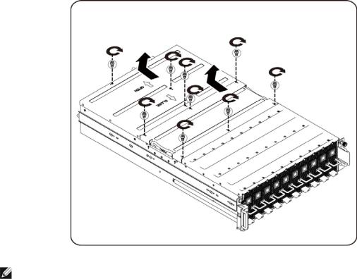
2.2. System Cover
 WARNING: Before you remove or install the system cover:
make sure the server is not turned on or connected to the AC power.
Follow these instructions to remove the system cover:
1.Loosen and remove the securing screw on the top of the system.
2.Slide the cover horizontally to the back using the traction pad and remove the cover in the direction of the arrow.
NOTE: |
This system must be operated with the system cover installed to ensure proper cooling. |
Follow these instructions to install the system cover:
Reverse the steps above to install the system cover.
8
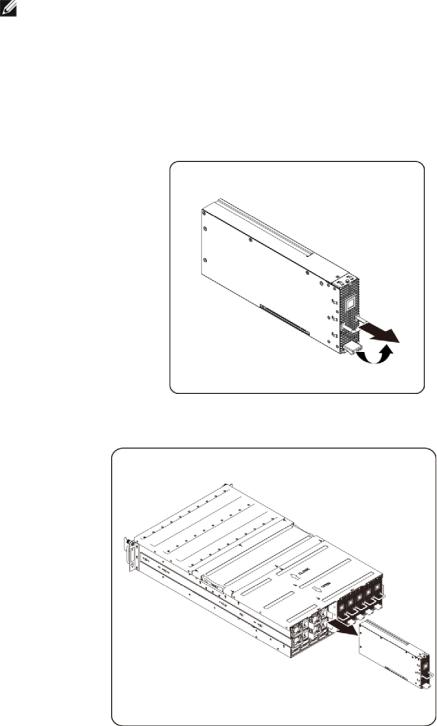
2.3. GPGPU Cage
NOTE: |
When you remove or install the GPGPU cage, note the following points: |
Take note of the drive tray orientation before sliding it out.
The tray will not fit back into the bay if inserted incorrectly.
Follow these instructions to remove the cage:
1. Press the release button along the direction of the arrow.
2. Slide the cage assembly out of the system.
Follow these instructions to install the cage:
Reverse the steps above to install the cage.
9
2.4. Replacing GPGPU Card
 WARNING: Before you remove or install the system fan, take the steps below:
Make sure the system is not turned on or connected to the AC power.
Disconnect all necessary cable connections.
Turn off the specific single GPU cage power.
Failure to observe these warnings could result in personal injury or damage to the equipment.
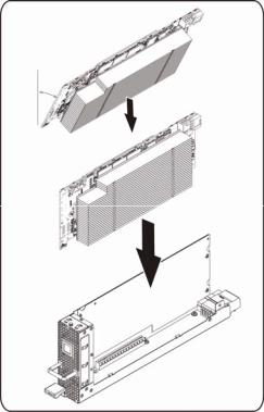
Follow these instructions to replace a GPGPU card:
For M1060 System
1. Insert the GPGPU card by 45 degree and push it into socket vertically.
10
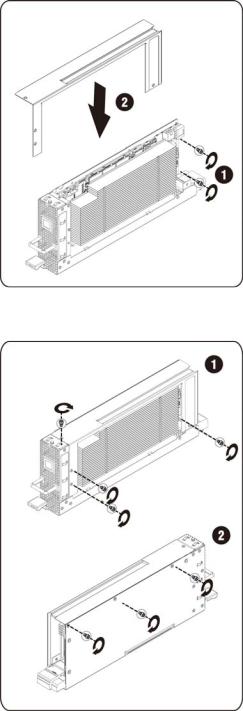
2. Secure the card in place with screws and place the GPGPU side cover as illustration arrow show.
3. Secure the GPGPU side cover and back cover in place with screws.
11
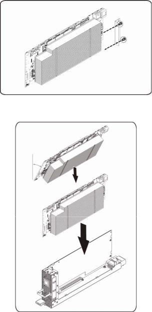
Follow these instructions to replace a GPGPU card:
For M2050 System
1. Attach the support bracket on the GPGPU board and secure it in place with screws.
2. Insert the GPGPU card by 45 degree and push it into socket vertically.
12
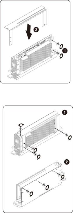
3. Secure the card in place with screws and place the GPGPU side cover as illustration arrow show.
4. Secure the card in place with screws and place the GPGPU side cover as illustration arrow show.
13
2.5. System Fans
In case a of system fan failure, you can quickly replace the system fan.
 WARNING: Before you remove or install the system fan, take the steps below:
Make sure the system is not turned on or connected to the AC power.
Disconnect all necessary cable connections.
Failure to observe these warnings could result in personal injury or damage to the equipment.
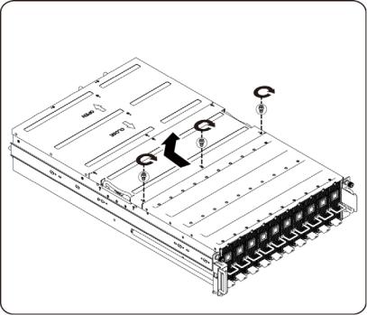
Follow the instruction to remove the system fan:
1. Loosen and remove the securing screw on the top of the system.
14

2. Lift the system fan out of the system fan cage.
Follow these instructions to install the system fan:
Reverse the step above to install the system fan.
15
 Loading...