


Dell™ Inspiron™ 1525/1526 Service Manual
Before You Begin |
Speaker Assembly |
Subscriber Identity Module (Optional) |
Palm Rest |
ExpressCards |
ExpressCard Cage |
Using the Memory Card Reader |
Processor Thermal-Cooling Assembly |
Optical Drive |
Processor Module |
Hard Drive |
Wireless Mini-Cards |
Center Control Cover |
System Board Assembly |
Internal Card With Bluetooth® Wireless Technology |
Coin-Cell Battery |
Keyboard |
Battery Latch Assembly |
Button Board |
Flashing the BIOS |
Memory |
Pin Assignments for I/O Connectors |
Display |
|
|
|
Notes, Notices, and Cautions
NOTE: A NOTE indicates important information that helps you make better use of your computer.
NOTICE: A NOTICE indicates either potential damage to hardware or loss of data and tells you how to avoid the problem.
CAUTION: A CAUTION indicates potential for property damage, personal injury, or death.
Information in this document is subject to change without notice.
© 2007–2008 Dell Inc. All rights reserved.
Reproduction in any manner whatsoever without the written permission of Dell Inc. is strictly forbidden.
Trademarks used in this text: Dell, the DELL logo, and Inspiron are trademarks of Dell Inc.; Microsoft, Windows, and Windows Vista are either trademarks or registered trademarks of Microsoft Corporation in the United States and/or other countries.
Other trademarks and trade names may be used in this document to refer to either the entities claiming the marks and names or their products. Dell Inc. disclaims any proprietary interest in trademarks and trade names other than its own.
Model PP29L
January 2008 |
Rev. A00 |

Back to Contents Page
Before You Begin
Dell™ Inspiron™ 1525/1526 Service Manual
Recommended Tools
Before Working Inside Your Computer
This document provides procedures for removing and installing the components in your computer. Unless otherwise noted, each procedure assumes that:
•You have performed the steps in Before Working Inside Your Computer.
•You have read the safety information in your Dell Product Information Guide.
•When replacing a component, you have already removed the original, if installed.
NOTE: The color of your system and certain system components may appear differently than shown in this document.
Recommended Tools
The procedures in this document may require the following tools:
•Small flat-blade screwdriver
•Phillips screwdriver
•Small plastic scribe
•Flash BIOS update (see the Dell Support website at support.dell.com)
Before Working Inside Your Computer
Use the following safety guidelines to help protect your computer from potential damage and to help ensure your own personal safety.
CAUTION: Before you begin any of the procedures in this section, follow the safety instructions in the Product Information Guide.
NOTICE: Only a certified service technician should perform repairs on your computer. Damage due to servicing that is not authorized by Dell is not covered by your warranty.
NOTICE: To avoid electrostatic discharge, ground yourself by using a wrist grounding strap or by periodically touching an unpainted metal surface, such as a connector on the back of the computer.
NOTICE: Handle components and cards with care. Do not touch the components or contacts on a card. Hold a card by its edges or by its metal mounting bracket. Hold a component such as a processor by its edges, not by its pins.
NOTICE: When disconnecting a cable, pull on the cable's connector or on its strain-relief loop, not on the cable itself. For cable connectors with locking tabs, press inward on the locking tabs to release the connector. When connecting a cable, ensure that the connectors are correctly oriented and aligned to avoid damage to the connector and/or the connector's pins.
1.Ensure that the work surface is flat and clean to prevent the computer cover from being scratched.
2.Click Start  , click the arrow
  icon, and then click Shut Down to turn off your computer.
NOTE: Ensure that the computer is off and not in a power management mode. If you cannot shut down the computer using the operating system, press and hold the power button for 4 seconds.
3. Disconnect your computer and all attached devices from their electrical outlets.
NOTICE: To disconnect a network cable, first unplug the cable from your computer, and then unplug it from the network wall jack.
4.Disconnect any telephone or network cables from the computer.
5.Remove any installed cards from the ExpressCard slot (see Removing an ExpressCard or Blank) and the 8-in-1 memory card reader (see Removing a Memory Card or Blank).
NOTICE: To help prevent damage to the system board, you must remove the battery from the battery bay before you service the computer.
NOTE: To avoid damage to the computer, use only the battery designed for this particular Dell computer. Do not use batteries designed for other Dell computers.
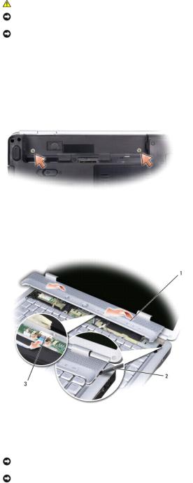
6. Turn the computer over.
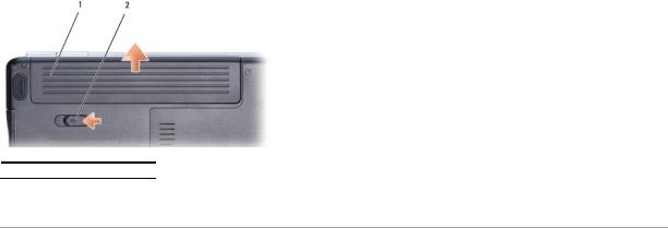
7.Slide the battery release latch until they click into place.
8.Slide the battery out of the battery bay.
 1
1  battery
  2
2  battery release latch
9. Turn the computer top-side up, open the display, and press the power button to ground the system board.
Back to Contents Page

Back to Contents Page
Flashing the BIOS
Dell™ Inspiron™ 1525/1526 Service Manual
Flashing the BIOS From a CD
Flashing the BIOS From the Hard Drive
If a BIOS-update program CD is provided with a new system board, flash the BIOS from the CD. If you do not have a BIOS-update program CD, flash the BIOS from the hard drive.
Flashing the BIOS From a CD
NOTICE: Plug the AC adapter into a known good power source to prevent a loss of power. Failure to do so may cause system damage.
1. Ensure that the AC adapter is plugged in and that the main battery is installed properly.
NOTE: If you use a BIOS update program CD to flash the BIOS, press <F12> before inserting the CD so that you can set up the computer to boot from a CD for one time only. Otherwise, you must enter the system setup program to change the default boot order.
2. Insert the BIOS-update program CD, and turn on the computer.
NOTICE: Do not interrupt this process once it begins. Doing so may cause system damage.
Follow the instructions that appear on the screen. The computer continues to boot and updates the new BIOS. When the flash update is complete, the computer will automatically reboot.
3.Press <F2> during POST to enter the system setup program.
4.Press <Alt> and <f> to reset the computer defaults.
5.Press <Esc>, select Save/Exit, and press <Enter> to save configuration changes.
6.Remove the flash BIOS update program CD from the drive and restart the computer.
Flashing the BIOS From the Hard Drive
NOTICE: Plug the AC adapter into a known good power source to prevent a loss of power. Failure to do so may cause system damage.
1.Ensure that the AC adapter is plugged in, the main battery is properly installed, and a network cable is attached.
2.Turn on the computer.
3.Locate the latest BIOS update file for your computer at support.dell.com.
4.Click Download Now to download the file.
5.If the Export Compliance Disclaimer window appears, click Yes, I Accept this Agreement.
The File Download window appears.
6.Click Save this program to disk, and then click OK.
The Save In window appears.
7.Click the down arrow to view the Save In menu, select Desktop, and then click Save.
The file downloads to your desktop.
8.Click Close if the Download Complete window appears.
The file icon appears on your desktop and is titled the same as the downloaded BIOS update file.

9. Double-click the file icon on the desktop and follow the instructions on the screen.
Back to Contents Page
Back to Contents Page
Internal Card With Bluetooth® Wireless Technology
Dell™ Inspiron™ 1525/1526 Service Manual
CAUTION: Before you begin any of the procedures in this section, follow the safety instructions in the Product Information Guide.
NOTICE: To avoid electrostatic discharge, ground yourself by using a wrist grounding strap or by periodically touching an unpainted metal surface (such as a connector on the back of the computer).
NOTICE: To help prevent damage to the system board, you must remove the battery from the battery bay before you begin working inside the computer.
Removing the Internal Card With Bluetooth® Wireless Technology
1.Follow the procedures in Before You Begin.
2.Remove the center control cover (see Removing the Center Control Cover).
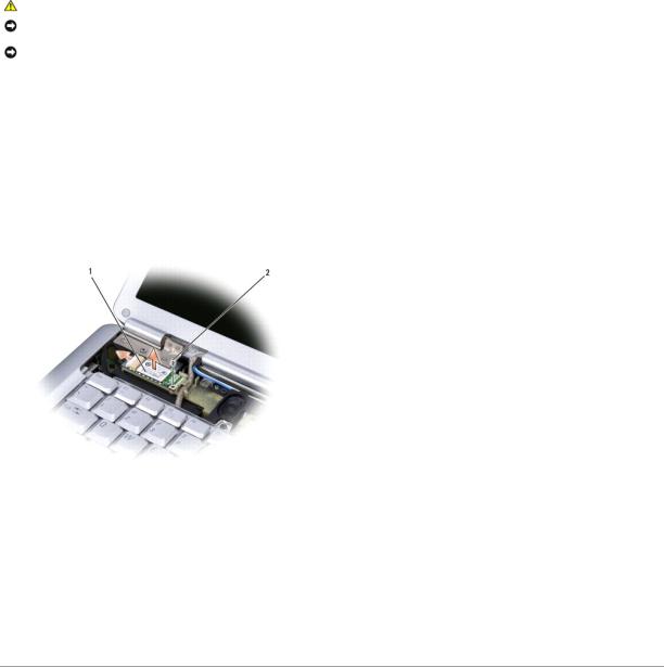
3.Remove the screw securing the card.
4.Grasp the connector end of the card and slide it out from under the securing tabs.
5.Disconnect the cable from the card.
1 |
card |
2 |
securing screw |
|
|
|
|
Replacing the Internal Card With Bluetooth® Wireless Technology
1.Connect the cable to the card.
2.Slide the card at an angle into the card compartment and replace the securing screw.
3.Replace the center control cover (see Replacing the Center Control Cover).
Back to Contents Page
Back to Contents Page
Button Board
Dell™ Inspiron™ 1525/1526 Service Manual
CAUTION: Before you begin any of the procedures in this section, follow the safety instructions in the Product Information Guide.
NOTICE: To avoid electrostatic discharge, ground yourself by using a wrist grounding strap or by periodically touching an unpainted metal surface (such as a connector on the back of the computer).
NOTICE: To help prevent damage to the system board, you must remove the battery from the battery bay before you begin working inside the computer.
Removing the Button Board
1.Follow the procedures in Before You Begin.
2.Remove the center control cover (see Removing the Center Control Cover).
3.Remove the keyboard (see Removing the Keyboard).
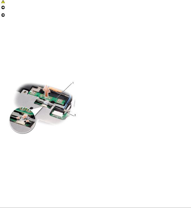
4.Disconnect the button board cable from the system board.
5.Gently pry up the button board from the securing tabs starting from the top left corner.
1 |
button board |
2 |
button board cable |
|
|
|
|
Replacing the Button Board
1.To replace the button board, remove the palm rest (see Removing the Palm Rest).
2.Connect the button board cable to the system board.
3.Place the button board in position and gently press until the button board secures within the tabs.
4.Replace the keyboard (see Replacing the Keyboard).
5.Replace the center control cover (see Replacing the Center Control Cover).
Back to Contents Page
Back to Contents Page
Using the Memory Card Reader
Dell™ Inspiron™ 1525/1526 Service Manual
Removing a Memory Card or Blank
CAUTION: Before you begin any of the procedures in this section, follow the safety instructions in the Product Information Guide.
NOTICE: Use the memory card configuration utility (click the  icon in the notification area) to select a card and stop it from functioning before you remove it from the computer. If you do not stop the card in the configuration utility, you may lose data.
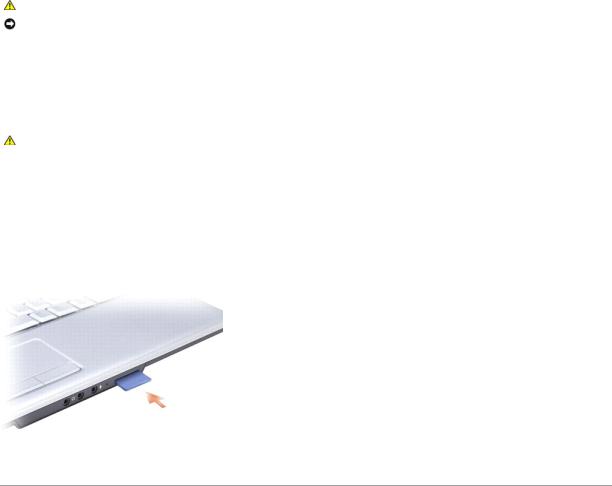
Press the card into the slot to release it from the card reader. When it is partially ejected, remove the card.
Installing a Memory Card
CAUTION: Before you begin any of the procedures in this section, follow the safety instructions in the Product Information Guide.
You can install a memory card in the computer while the computer is running. The computer automatically detects the card.
Memory cards are generally marked with a symbol (such as a triangle or an arrow) or a label to indicate which end to insert into the slot. The cards are keyed to prevent incorrect insertion. If card orientation is not clear, see the documentation that came with the card.
1.Hold the card with the top side of the card facing up.
2.Slide the card into the slot until the card is completely seated in its connector.
If you encounter too much resistance, do not force the card. Check the card orientation and try again.
The computer recognizes the memory card and automatically loads the appropriate device driver. If the configuration program tells you to load the manufacturer's drivers, use the media that came with the memory card, if applicable.
Back to Contents Page
Back to Contents Page
Center Control Cover
Dell™ Inspiron™ 1525/1526 Service Manual
CAUTION: Before you begin any of the procedures in this section, follow the safety instructions in the Product Information Guide.
NOTICE: To avoid electrostatic discharge, ground yourself by using a wrist grounding strap or by periodically touching an unpainted metal surface (such as a connector on the back of the computer).
NOTICE: To help prevent damage to the system board, you must remove the battery from the battery bay before you begin working inside the computer.
Removing the Center Control Cover
1.Follow the procedures in Before You Begin.
2.Remove the two screws securing the center control cover from the battery bay.
3.Turn the computer top side up, and open the display as far as it will open.
4.Insert a plastic scribe into the indent to lift the center control cover on the right side and ease the center control cover up.
1 |
center control cover |
2 |
scribe |
3 |
media control buttons connector |
|
|
|
|
|
|
5. Disconnect the cable from the media control buttons connector located underneath the center control cover.
NOTICE: To avoid damage to the data cable connected to the system board, ensure that you do not pull hard when you are raising the center control cover.
NOTICE: To avoid damage to the center control cover, do not lift the cover on both sides simultaneously.
6.Remove the center control cover.
7.Remove the two screws at the top of the keyboard.
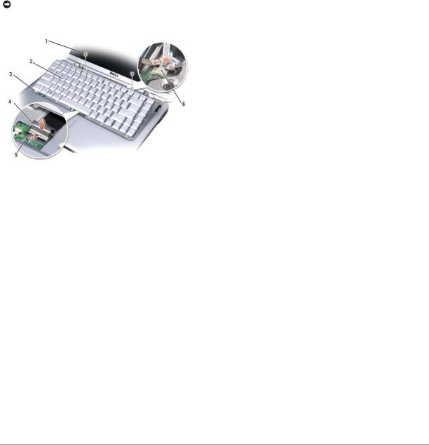
NOTICE: The key caps on the keyboard are fragile, easily dislodged, and time-consuming to replace. Be careful when removing and handling the keyboard.
1 |
screws (2) |
2 |
keyboard |
|
|
|
|
3 |
keyboard tabs (5) |
4 |
keyboard cable |
5 |
keyboard connector latch |
6 |
media control buttons connector |
|
|
|
|
8.Lift the keyboard and hold it up and slightly forward to access to the media control buttons connector.
9.Disconnect the media control buttons connector and remove the media control buttons cable.
Replacing the Center Control Cover
1.Reconnect the media control buttons cable to the connector below the keyboard.
2.Align the tabs along the bottom of the keyboard and slide them under the palm rest.
3.Press on the right edge near the top to snap the keyboard into place.
4.Replace the two screws on the top of the keyboard.
5.Reconnect the media control buttons connector to the center control cover.
6.Insert the left edge of the center control cover.
7.Press from left to right until the cover snaps into place.
8.In the battery bay, replace the two screws that secure the center control cover.
Back to Contents Page

Back to Contents Page
Coin-Cell Battery
Dell™ Inspiron™ 1525/1526 Service Manual
Removing the Coin-Cell Battery
Replacing the Coin-Cell Battery
Removing the Coin-Cell Battery
CAUTION: Before you begin any of the procedures in this section, follow the safety instructions in the Product Information Guide.
1.Follow the instructions in Before You Begin.
2.Remove all memory module (see Removing Memory Module).
3.Remove the hard drive (see Removing the Hard Drive).
4.Remove the optical drive (see Removing the Optical Drive).
5.Remove all Mini-Cards (see Removing Mini-Card).
6.Remove the center control cover (see Removing the Center Control Cover).
7.Remove the keyboard (see Removing the Keyboard).
8.Remove the display assembly (see Removing the Display Assembly).
9.Remove the internal card with Bluetooth wireless technology, if installed (see Removing the Internal Card With Bluetooth® Wireless Technology).
10.Remove the palm rest (see Removing the Palm Rest).
11.Remove the ExpressCard cage (see Removing the ExpressCard Cage).
12.Remove the processor thermal-cooling assembly (see Removing the Processor Thermal-Cooling Assembly).
13.Remove the processor (see Removing the Processor Module).
14.Remove the system board (see Removing the System Board Assembly).
15.Use a plastic scribe to pry up the coin-cell battery from the slot.
1 system board |
2 slot |
3 coin-cell battery

Replacing the Coin-Cell Battery
CAUTION: Before you begin the following procedure, follow the safety instructions in the Product Information Guide.
1.Hold the coin-cell battery with the positive side up.
2.Slide the coin-cell battery into the slot and gently press until it snaps to the slot.
3.Follow the steps in Removing the Coin-Cell Battery in the reverse order.
Back to Contents Page

Back to Contents Page
Processor Module
Dell™ Inspiron™ 1525/1526 Service Manual
Removing the Processor Module
CAUTION: Before you begin the following procedure, follow the safety instructions in the Product Information Guide.
1.Follow the instructions in Before You Begin.
2.Remove the processor thermal-cooling assembly (see Removing the Processor Thermal-Cooling Assembly).
NOTICE: To avoid damage to the processor, hold the screwdriver so that it is perpendicular to the processor when turning the cam screw.
3. To loosen the ZIF socket, use a small, flat-blade screwdriver and rotate the ZIF-socket cam screw counterclockwise until it comes to the cam stop.
 1
1  ZIF-socket cam screw
  2
2  ZIF socket
NOTICE: To ensure maximum cooling for the processor, do not touch the heat transfer areas on the processor thermal-cooling assembly. The oils in your skin can reduce the heat transfer capability of the thermal pads.
NOTICE: When removing the processor module, pull the module straight up. Be careful not to bend the pins on the processor module.
4. Lift the processor module from the ZIF socket.
Replacing the Processor Module
CAUTION: Before you begin the following procedure, follow the safety instructions in the Product Information Guide.
NOTICE: Do not touch the processor die. Press and hold the processor down on the substrate on which the die is mounted while turning the cam screw to prevent intermittent contact between the cam screw and processor.
NOTICE: Ensure that the cam lock is in the fully open position before seating the processor module. Seating the processor module properly in the ZIF socket does not require force. A processor module that is not properly seated can result in an intermittent connection or permanent damage to the microprocessor and ZIF socket.
NOTE: If a new processor is installed, you will receive a new thermal-cooling assembly, which will include an affixed thermal pad, or you will receive a new thermal pad along with a tech sheet to illustrate proper installation.
1. Align the pin-1 corner of the processor module with the pin-1 corner of the ZIF socket, then insert the processor module.
NOTE: The pin-1 corner of the processor module has a triangle that aligns with the triangle on the pin-1 corner of the ZIF socket.
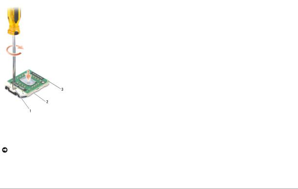
When the processor module is properly seated, all four corners are aligned at the same height. If one or more corners of the module are higher than the others, the module is not seated properly.
1 |
ZIF-socket cam screw |
2 |
ZIF socket |
|
|
|
|
3 |
pin-1 corner |
|
|
|
|
|
|
NOTICE: To avoid damage to the processor, hold the screwdriver so that it is perpendicular to the processor when turning the cam screw.
2.Tighten the ZIF socket by turning the cam screw clockwise to secure the processor module to the system board.
3.Replace the processor thermal-cooling assembly (see Replacing the Processor Thermal-Cooling Assembly).
Back to Contents Page
Back to Contents Page
Processor Thermal-Cooling Assembly
Dell™ Inspiron™ 1525/1526 Service Manual
Removing the Processor Thermal-Cooling Assembly
CAUTION: Before you begin the following procedure, follow the safety instructions in the Product Information Guide.
1.Follow the instructions in Before You Begin.
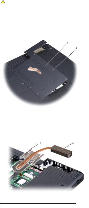
2.Turn the computer over.
3.Remove the eight captive screws securing the back cover and remove the module cover.
1 |
module cover |
2 |
captive screws (8) |
|
|
|
|
4.In sequential order, loosen the five captive screws securing the processor thermal-cooling assembly to the system board, then carefully lift the processor thermal-cooling assembly out of the computer.
 1
1  captive screws (5)
  2
2  processor thermal-cooling assembly
Replacing the Processor Thermal-Cooling Assembly

CAUTION: Before you begin the following procedure, follow the safety instructions in the Product Information Guide.
1.Align the five captive screws on the processor thermal-cooling assembly with the screw holes on the system board.
2.In sequential order, tighten the five captive screws to secure the processor thermal-cooling assembly to the system board.
3.Replace the module cover and tighten the eight captive screws.
Back to Contents Page
 Loading...