


N6
Project ___ ____________________ ___________
Item _________________ ___________________
Quantity _________________ _______________
CSI Sec tion 11400
Approved ____________ ___________________
Date ____ _____________________ ___________
980 S. I sabella Rd.
Mt. Pleasa nt, Michigan 4885 8
Phone: 800 -733-8948 or 989 -773-7981
Fax: 800-669-0 619
www.delfield.co m
Shelleymatic
®
by Deleld
Specifications
Standard Features
Options &
Accessories
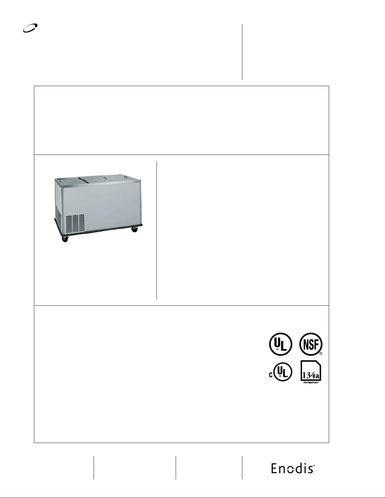
Cabinet top and corners to be 16-gauge
stainless steel
1” IPS drain
Units insulated with foamed in place
environmentally friendly, Kyoto Protocol
Compliant, Non ODP (Ozone Depletion
Potential), Non GWP (Global Warming
Potential) polyurethane
Units to have sliding stainless steel lids with
recessed handle
Sel f-leveli ng mec hanisms sha ll be
adjustable by adding and removing
stainless steel extension springs located
inside the elevator housing
Dispenser platform carrier shall be 18-
gauge stainless steel and removable for
cleaning
6” adjustable stainless steel legs
Refrigeration system shall be HFC-134A
refrigerant
Expansion valve and pressure control
9’ cord and plug
One year parts and 90 day labor standard
warranty
•
•
•
•
•
•
•
•
•
•
•
N6-1313-34 6 crate capacity, 34” height
N6-1313-36 6 crate capacity, 36” height
N10-1313-34 10 crate capacity, 34” height
•
•
•
N10-1313-36 10 crate capacity, 36” height
N14-1313-34 14 crate capacity, 34” height
N14-1313-36 14 crate capacity, 36” height
•
•
•
Models
N6/N10/N14
Free-Standing Self-Contained Milk Or Beverage Dispensers
N6/N10/N14 Free-Standing Self-Contained Milk Or Beverage Dispensers
4.00” (10.2cm) diameter swivel
casters (two locking) with corner
bumpers (adds 1.75” [4.4cm]
to overall length and depth and
reduces overall height by 1.00”
[2.5cm])
Wrap-around bumpers (adds 1.75”
[4.4cm] to overall length and
depth)
Lid lock ing device
Special voltages
Dial or digital style thermometer
•
•
•
•
•
N10- 1313-36
Ex terio r si des s hall be 20 -gau ge st ainle ss st eel. Top a nd co rner
sup por ts sh all b e 16- gaug e sta inle ss st eel, welde d, gr ound and
pol ishe d in to o ne i nteg ral unit .
Int erio r lin er sh all be wa ter-t ight and c onst ruct ed of 22-g auge
sta inle ss ste el wit h a 1.00 ” ( 2.54c m) I.P.S . drai n. Uni t shal l be
ins ulat ed with hig h-d ensit y, foame d-in -pla ce e nvir onmen tall y
fri endl y, Kyo to Pr otoco l Com plia nt, N on OD P (Oz one D eple tion
Pot entia l), Non GW P (G loba l War ming Pot enti al) poly uret hane
ins ulat ion wi th a non -con duct ive top bre aker str ip. Ref rige rated
com part ment is equi pped wit h dra in p lumb ed t o a drain val ve
loc ated at the bott om of t he c ounte r. E ach open ing shal l ha ve
a st ainl ess s teel slidi ng li d rec essed hand les. T hree s tain less
ste el l ouver s sh all be ins tall ed i n th e end and sid es o f th e
cab inet to allo w pr oper air flo w to the con dens ing unit .
Eac h se lf-l evel ing mec han ism s hall b e fi eld a djus tab le by
add ing or rem oving sta inle ss st eel e xten sion spr ings in the
el evat or ho usin g i nsi de t he un it. T he el eva tors sh all b e
con nect ed by rem ovabl e plat form ca rrie rs cons truc ted of 18 -
gau ge s tain less ste el.
Re fri ger ati on sys tem sh all u se HF C-1 34a re fri ger ant.
Ref rige rant flo w sh all be con trol led by an ex pansi on v alve .
Cab inet s hall m aint ain 36 °F to 40 °F (2°C to 4°C ) temp eratu re
wit h lid s clo sed fo r sto rage . R efri gera tion sy stem sh all b e
con trol led by a p ressu re contr ol, loca ted near th e c onden sing
uni t.
Ele ctr ical conn ecti ons s hall be 11 5 vol t, 60 cycl e, si ngle phas e.
Uni t sh all have a 9’ ( 2.7m) lon g el ectr ical cord and NEMA 5-15 P
plu g. Exte rior has an ON/ OFF swit ch.
Leg s: U nit shal l be moun ted on 6 .00” ( 15.2 cm) high adju stab le
sta inle ss s teel leg s.
NOT E: T his equ ipme nt is inte nded fo r s tora ge and /or d ispl ay
of pre -pac kage d or bot tled pro duct s on ly.
 Loading...