

Page 1
DATA SHEET
PHOTO DIODE
NDL5471R Series
1 000 to 1 600 nm OPTICAL FIBER COMMUNICATIONS
φφφφ
DESCRIPTION
The NDL5471R Series is an InGaAs PIN photo diode receptacle module especially designed for a detector of long
wavelength optical fiber communications systems. It covers the wavelength range between 1 000 and 1 600 nm with
high efficiency.
FEATURES
• Small dark current ID = 0.1 nA
• High quantum efficiency
• Cut-off frequency fC = 1.5 GHz MIN.
• Detecting area size
• Low operating voltage
120
µµµµ
m InGaAs PIN PHOTO DIODE RECEPTACLE MODULE
= 86 % @ λ = 1 300 nm
η
= 80 % @ λ = 1 550 nm
η
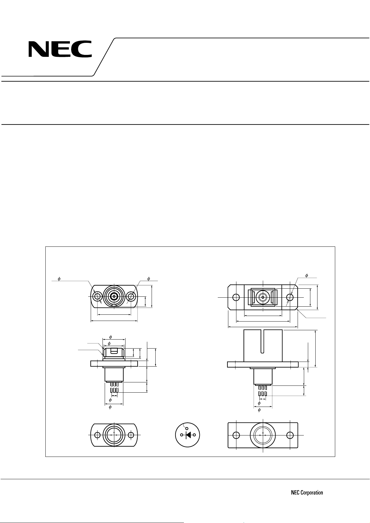
120 µm
φ
2– 4 Depth±1.5
M8×0.75
NDL5471RC
for FC Connector
13.44±0.1
19±0.1
C0.5
3
7.92
4
8.5
2.0
6.8
PACKAGE DIMENSIONS
in millimeters
2– 2.2
8.9±0.1
3.5
3.4
4.4
2.0±0.1
8.0±0.1
6.0±0.1
12.5
MIN.
PIN CONNECTIONS
Case
4
1
1
Cathode Anode
3
NDL5471RD
for SC Connector
12.8±0.3
18.0±0.1
22.0±0.3
2.0
6.8
4
3
1
2– 2.3
4–C1.0
2.0±0.1
6.0±0.1
12.5
MIN.
7.4
9.4±0.1
14.2±0.2
The information in this document is subject to change without notice. Before using this document, please
confirm that this is the latest version.
Not all devices/types available in every country. Please check with local NEC representative for
availability and additional information.
Document No. P10263EJ4V0DS00 (4th edition)
Date Published April 1999 NS CP(K)
Printed in Japan
The mark
••••
shows major revised points.
©
1995, 1999
Page 2

ORDERING INFORMATION
Part Number Device Type
NDL5471RC FC type receptacle module
NDL5471RD SC type receptacle module
NDL5471R Series
ABSOLUTE MAXIMUM RATINGS (TA = 25
C, unless otherwise specified)
°°°°
Parameter Symbol Ratings Unit
Reverse Voltage V
Forward Current I
Reverse Current I
Optical Input Power P
Operating Case Temperature T
Storage Temperature
R
F
R
in
C
stg
T
20 V
10 mA
0.5 mA
8mW
–40 to +85 °C
–40 to +85 °C
ELECTRO-OPTICAL CHARACTERISTICS (TC = 25
Parameter Symbol Conditions MIN. TYP. MAX. Unit
Dark Current I
Terminal Capacitance C
Quantum Efficiency
Responsivity S
Cut-off Frequency f
D
VR = 5 V 0.1 1.0 nA
t
VR = 5 V, f = 1.0 MHz 1.1 1.5 pF
= 1 300 nm, V
η
λ
= 1 550 nm, V
λ
= 1 300 nm, VR = 5 V 0.78 0.89 A/W
λ
= 1 550 nm, V
λ
C
VR = 5 V, RL = 50 Ω, −3dB 1.5 GHz
C)
°°°°
R
= 5 V 75 86 %
R
= 5 V 80
R
= 5 V 1.0
2
Data Sheet P10263EJ4V0DS00
Page 3

TYPICAL CHARACTERISTICS (TC = 25 °C, unless otherwise specified)
NDL5471R Series
WAVELENGTH DEPENDENCE
OF QUANTUM EFFICIENCY
100
80
η
60
40
20
Quantum Efficiency (%)
0
0.9 1.0 1.1 1.31.2 1.4 1.5 1.6 1.7
Wavelength λ ( m)
µ
REVERSE VOLTAGE DEPENDENCE
OF DARK CURRENT
10
C
= +75 ˚C
T
1.0
(nA)
D
0.1
+50 ˚C
+25 ˚C
0 ˚C
–25 ˚C
10
∆
0
Responsivity (Relative Value) S/S (%)
–10
–60
10
1.0
(nA)
D
0.1
TEMPERATURE DEPENDENCE
OF RESPONSIVITY
λ = 1 300 nm
0
–20
–40
Case Temperature T
20 40 60 80
C
(˚C)
TEMPERATURE DEPENDENCE
OF DARK CURRENT
VR = 5 V
100
Dark Current I
0.01
0.001
Reverse Voltage V
FREQUENCY RESPONSE
Response (3dB/div.)
0
Dark Current I
0.01
0.001
10020
R
(V)
–60 –40 –20 0 20 40 60 80 100
REVERSE VOLTAGE DEPENDENCE
OF TERMINAL CAPACITANCE
5
(pF)
t
1
Terminal Capacitance C
0.5
0.01
2.5 5.0
Frequency f (GHz)
VR = 10 V
λ = 1 300 nm
RL = 50 Ω
C
R
(˚C)
(V)
Case Temperature T
0.1 1 10
Reverse Voltage V
f = 1.0 MHz
100
Remark
The graphs indicate nominal characteristics.
Data Sheet P10263EJ4V0DS00
3
Page 4

InGaAs PIN-PD
Part number P
(mW) (°C) (°C)
Absolute maximum ratings Typical characteristics (TC = 25°C)
in
C
T
stg
T
Detecting ID (nA) Ct (pF) S (A/W) f
area size
m)
(
µ
VR
(V)
TYP.
VR
(V)
TYP.
λ
(nm)
NDL5471R Series
C
Package
(GHz)
TYP.
MIN.
NDL5421P/P1/P2 8 –40 to +85 –40 to +85
NDL5422P – –40 to +70 –40 to +85
NDL5461P/P1/P2 8 –40 to +85 –40 to +85
NDL5471RC/RD 8 –40 to +85 –40 to +85
NDL5481P/P1/P2 8 –40 to +85 –40 to +85
50 5 0.1 5 0.7 1300 0.89 2.5 Coax i al
φ
1550 0.94
50 5 0.1 – – 1300 0.89 2.5 B utterfly with
φ
1550 1.00 AMP
80 5 0.1 5 1.0 1300 0.89 2.5 Coax i al
φ
1550 0.94
120 5 0.1 5 1.1 1300 0.89 1.5 Rec eptacle
φ
1550 1.00
80 10 0.1 10 0.7 1300 0.85 2.5 Coaxial
φ
4
Data Sheet P10263EJ4V0DS00
Page 5

NDL5471R Series
REFERENCE
Document Name Document No.
NEC semiconductor device reliability/quality control system C11159E
Quality grades on NEC semic onductor devices C11531E
Semiconductor device mounting technology manual C10535E
Semiconductor selection guide X10679E
Data Sheet P10263EJ4V0DS00
5
Page 6

[MEMO]
NDL5471R Series
6
Data Sheet P10263EJ4V0DS00
Page 7

[MEMO]
NDL5471R Series
Data Sheet P10263EJ4V0DS00
7
Page 8

NDL5471R Series
CAUTION
Within this device there exists GaAs (Gallium Arsenide) material which is a
harmful substance if ingested. Please do not under any circumstances break the
hermetic seal.
The export of this product from Japan is prohibited without governmental license. To export or re-export this product from
a country other than Japan may also be prohibited without a license from that country. Please call an NEC sales
representative.
• The information in this document is subject to change without notice. Before using this document, please
confirm that this is the latest version.
• No part of this document may be copied or reproduced in any form or by any means without the prior written
consent of NEC Corporation. NEC Corporation assumes no responsibility for any errors which may appear in
this document.
• NEC Corporation does not assume any liability for infringement of patents, copyrights or other intellectual property
rights of third parties by or arising from use of a device described herein or any other liability arising from use
of such device. No license, either express, implied or otherwise, is granted under any patents, copyrights or other
intellectual property rights of NEC Corporation or others.
• Descriptions of circuits, software, and other related information in this document are provided for illustrative
purposes in semiconductor product operation and application examples. The incorporation of these circuits,
software, and information in the design of the customer's equipment shall be done under the full responsibility
of the customer. NEC Corporation assumes no responsibility for any losses incurred by the customer or third
parties arising from the use of these circuits, software, and information.
• While NEC Corporation has been making continuous effort to enhance the reliability of its semiconductor devices,
the possibility of defects cannot be eliminated entirely. To minimize risks of damage or injury to persons or
property arising from a defect in an NEC semiconductor device, customers must incorporate sufficient safety
measures in its design, such as redundancy, fire-containment, and anti-failure features.
• NEC devices are classified into the following three quality grades:
"Standard", "Special", and "Specific". The Specific quality grade applies only to devices developed based on a
customer designated "quality assurance program" for a specific application. The recommended applications of
a device depend on its quality grade, as indicated below. Customers must check the quality grade of each device
before using it in a particular application.
Standard: Computers, office equipment, communications equipment, test and measurement equipment,
audio and visual equipment, home electronic appliances, machine tools, personal electronic
equipment and industrial robots
Special: Transportation equipment (automobiles, trains, ships, etc.), traffic control systems, anti-disaster
systems, anti-crime systems, safety equipment and medical equipment (not specifically designed
for life support)
Specific: Aircraft, aerospace equipment, submersible repeaters, nuclear reactor control systems, life
support systems or medical equipment for life support, etc.
The quality grade of NEC devices is "Standard" unless otherwise specified in NEC's Data Sheets or Data Books.
If customers intend to use NEC devices for applications other than those specified for Standard quality grade,
they should contact an NEC sales representative in advance.
M7 98. 8
 Loading...