

Page 1

Ultra-compact EMC/RFI filter for
three-phase systems and motor drives
available for the whole range
n Exceptional attenuation performance
from 150kHz to 30MHz
n Excellent saturation resistance up to
50m cable length
n Most compact and slim filter design
in its class
3-phase filters
FN 3258
Approvalsn New: solid safety connector blocks
Technical specifications
Maximum continuous operating voltage: 3x 480/277VAC (FN 3258)
3x 520/300VAC (FN 3258H)
Operating frequency: dc to 60Hz
Rated currents: 7 to 180A @ 50°C
High potential test voltage: P –> E 2650VDC for 2 sec
P –> P 2100VDC for 2 sec
Protection category: IP20
Overload capability: 4x rated current at switch on,
1.5x rated current for 1 minute, once per hour
Temperature range (operation and storage): -25°C to +100°C (25/100/21)
Flammability corresponding to: UL 94V-2 or better
Design corresponding to: UL 1283, CSA 22.2 No. 8 1986, EN 60939
MTBF @ 50°C/400V (Mil-HB-217F): 300,000 hours
Features and benefits
n The extremely compact and slim filter
design allows a trouble-free installation
even where the available mounting space
is minimal.
n With new additional filter types providing
safety terminal blocks, the most preferred
connection style can be chosen fast and
easy. This helps to stay in line with the
electrical connection concept of a given
n Filter operation on the mains input side
of consumers increases their reliability and
conducted immunity significant.
n Chokes with exceptional saturation resist-
ance and excellent thermal behavior are a
vital part of FN 3258 design. Thus, all filters
retain the expected filter performance
even in very noisy applications and under
full load conditions.
application.
n FN 3258 filters ensure compliance with
Class A limits according to EN 55011 up to
50m cable length and beyond. Further
they can contribute significantly to meet
conducted emission limits according to
Class B.
Typical electrical schematic
L1
L2
L3
Cx R1
PE
Line
L
Cx
Cy
R2
L1‘
L2‘
L3‘
PE
Load
Typical applications
n Three-phase variable speed motor drives,
servo drives, inverters and converters
n Applications comprising energy conversion
devices like machines or process auto-
mation equipment
n HVAC equipment, elevators, power
supplies, UPS and further three-phase
applications
Page 2
> Components > FN 3258
Filter selection table
Filter* Rated current Typical drive Leakage current*** Power loss Input/Output Weight
@ 50°C (40°C) power rating** @ 400VAC/50Hz @ 25°C/50Hz connections
[A] [kW] [mA] [W] [kg]
FN 3258-7-.. 7 (7.7) 4 33.0 3.8 -45 -44 0.5
FN 3258-16-.. 16 (17.5) 7.5 33.0 6.1 -45 -44 0.8
FN 3258-30-.. 30 (32.9) 15 33.0 11.8 -47 -33 1.2
FN 3258-42-.. 42 (46.0) 22 33.0 15.7 -47 -33 1.4
FN 3258-55-.. 55 (60.2) 30 33.0 25.9 -52 -34 2.0
FN 3258-75-.. 75 (82.2) 37 33.0 32.2 -52 -34 2.7
FN 3258-100-35 100 (109.5) 55 33.0 34.5 -35 4.3
FN 3258-130-35 130 (142.4) 75 33.0 43.1 -35 4.5
FN 3258-180-40 180 (197.1) 90 33.0 58.3 -40 6.0
FN 3258H-7-.. 7 (7.7) 4 33.0 3.8 -45 -44 0.5
FN 3258H-16-.. 16 (17.5) 7.5 33.0 6.1 -45 -44 0.8
FN 3258H-30-.. 30 (32.9) 18.5 33.0 11.8 -47 -33 1.2
FN 3258H-42-.. 42 (46.0) 22 33.0 15.7 -47 -33 1.4
FN 3258H-55-.. 55 (60.2) 37 33.0 25.9 -52 -34 2.0
FN 3258H-75-.. 75 (82.2) 45 33.0 32.2 -52 -34 2.7
FN 3258H-100-35 100 (109.5) 55 33.0 34.5 -35 4.3
FN 3258H-130-35 130 (142.4) 75 33.0 43.1 -35 4.5
FN 3258H-180-40 180 (197.1) 110 33.0 58.3 -40 6.0
* To compile a complete part number, please replace the -.. with the required I/O connection style.
** Calculated at rated current, 440VAC (FN 3258)/480VAC (FN 3258H) and cos phi = 0.8. The exact value depends upon the efficiency of the drive, the motor and the entire application.
*** Maximum leakage under normal operating conditions. Note: if two phases are interrupted, worst case leakage could reach 5.4 times higher levels.
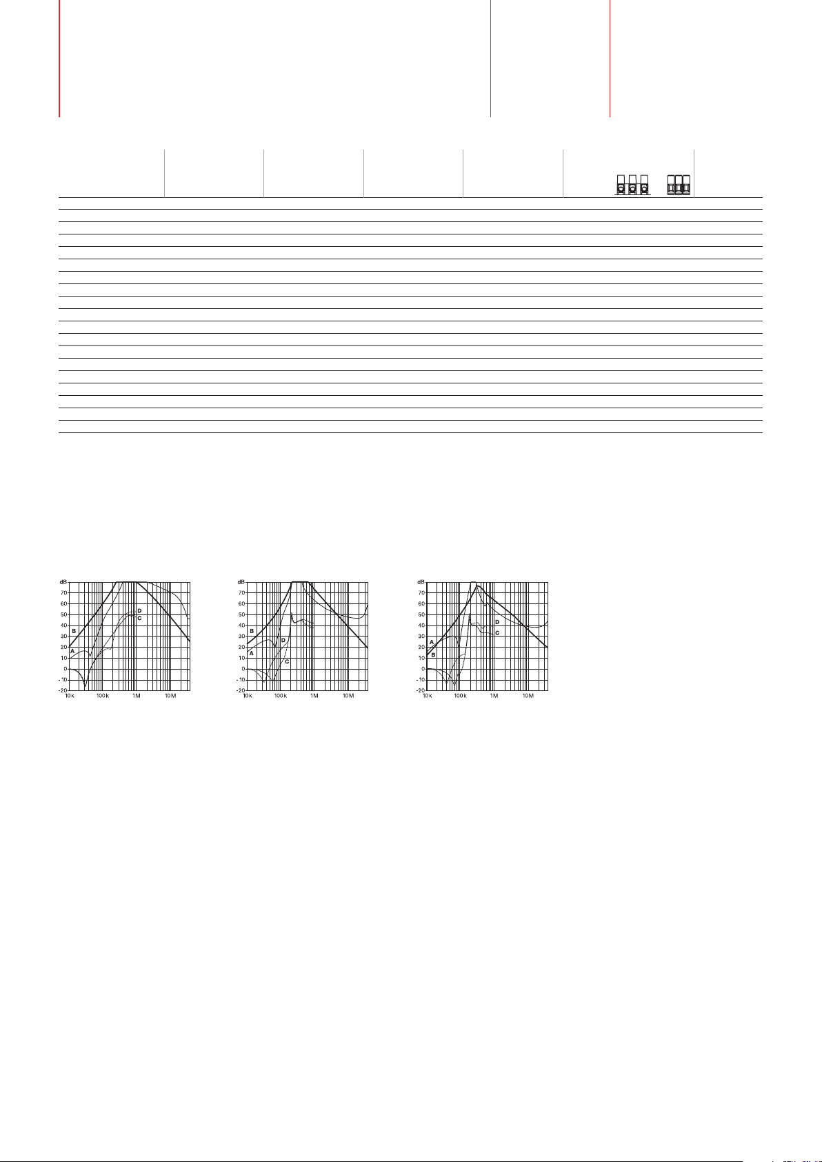
Typical filter attenuation
Per CISPR 17; A = 50Ω/50Ω sym; B = 50Ω/50Ω asym; C = 0.1Ω/100Ω sym; D = 100Ω/0.1Ω sym
7 to 42A types 55 to 100A types
130 and 180A types
Page 3

> Components > FN 3258
Mechanical data
Filters with strip terminals (7 to 75A types) Filters with safety connector blocks (7 to 180A types)
D I
J
1
C
C
J
1
L
D
2
I
C
2
L
A
G
E
Note: in favour of a better readability, connectors and earth studs are not shown in the horizontal projection.
H
K
B
F
G
A
E
H
K
F
Dimensions
7A 16A 30A 42A 55A 75A 100A 130A 180A
A 190 250 270 310 250 270 270 270 380
B 40 45 50 50 85 80 90 90 120
C 70 70 85 85 90 135 150 150 170
D 160 220 240 280 220 240 240 240 350
E 180 235 255 295 235 255 255 255 365
F 20 25 30 30 60 60 65 65 102
G 4.5 5.4 5.4 5.4 5.4 6.5 6.5 6.5 6.5
H 1 1 1 1 1 1.5 1.5 1.5 1.5
I1 10.6 10.6 12.6 12.6 19 19
I2 22 22 25 25 39 39 45 45 49.5
J M5 M5 M5 M6 M6 M6 M10 M10 M10
K 20 22.5 25 25 42.5 40 45 45 60
L1 31 31 40 40 45 60
L2 29.5 29.5 39.5 37.5 26.5 70.5 64 64 47
All dimensions in mm; 1 inch = 25.4mm
Tolerances according: ISO 2768 / EN 22768
B
Filter input/output connector cross sections
-33 -34 -35 -40 -44 -45 -47 -52
2
Solid wire 16mm
35mm2 50mm2 95mm2 10mm2 6mm2 16mm2 25mm
Flex wire 10mm2 25mm2 50mm2 95mm2 6mm2 4mm2 10mm2 16mm
2
2
AWG type wire AWG 6 AWG 2 AWG 1/0 AWG 4/0 AWG 8 AWG 12 AWG 8 AWG 4
Recommended torque 1.5 - 1.8Nm 4.0 - 4.5Nm 7 - 8Nm 17 - 20Nm 1.5 - 1.8Nm 0.7 - 0.8Nm 1.9 - 2.2Nm 1.9 - 2.2Nm
Please visit www.schaffner.com to find more details on filter connectors.
Your local partner: To find your local partner within Schaffner’s global network, please go to www.schaffner.com October 2006
 Loading...