


DS4800
QUICK REFERENCE GUIDE
3 |
4 |
2
1
5
|
|
Figure A |
6 |
|
|
|
|
1 |
"POWER ON" LED |
4 |
Display |
2 |
Focus Adjustment |
5 |
Laser Beam Output Window |
3 |
Indicator LEDs |
6 |
Push Button |
|
This manual illustrates a Stand Alone application. For other types of installations, such as |
|
ID-NET™, Pass-Through, Multiplexer Layout, etc. and for a complete scanner configuration using |
|
Genius™ configuration program, refer to the DS4800 Reference Manual available on the CD. |
NOTE |
This manual is also downloadable from the Web at www.automation.datalogic.com/ds4800. |

DS4800 QUICK GUIDE
UPDATES AND LANGUAGE AVAILABILITY
UK/US
The latest drivers and documentation updates for this product are available on Internet. Log on to: www.automation.datalogic.com
I
Su Internet sono disponibili le versioni aggiornate di driver e documentazione di questo prodotto. Questo manuale è disponibile anche nella versione italiana.
Collegarsi a: www.automation.datalogic.com
F
Les versions mises à jour de drivers et documentation de ce produit sont disponibles sur Internet. Ce manuel est aussi disponible en version française.
Cliquez sur : www.automation.datalogic.com
D
Im Internet finden Sie die aktuellsten Versionen der Treiber und Dokumentation von diesem Produkt. Die deutschsprachige Version dieses Handbuches ist auch verfügbar.
Adresse : www.automation.datalogic.com
E
En Internet están disponibles las versiones actualizadas de los drivers y documentación de este producto. También está disponible la versión en español de este manual.
Dirección Internet : www.automation.datalogic.com
SERVICES AND SUPPORT
Datalogic provides several services as well as technical support through its website. Log on to www.automation.datalogic.com and click on the links indicated for further information including:
•PRODUCTS
Search through the links to arrive at your product page where you can download specific Manuals and
Software & Utilities including:
-Genius™ a utility program, which allows device configuration using a PC. It provides RS232 interface configuration.
•SERVICES & SUPPORT
-Datalogic Services - Warranty Extensions and Maintenance Agreements
-Authorised Repair Centres
•CONTACT US
E-mail form and listing of Datalogic Subsidiaries
2
DS4800 QUICK GUIDE
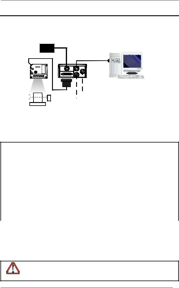
STEP 1 – CONNECT THE SYSTEM
To connect the system in a Stand Alone configuration, you need the hardware indicated in Figure 1. In this layout the data is transmitted to the Host on the main serial interface. In Local Echo communication mode, the RS232 auxiliary interface can be used to transmit data independently from the main interface selection. When On-Line Operating mode is used, the scanner is activated by an External Trigger (photoelectric sensor) when the object enters its reading zone.
PG 6000
MAIN
DS4800 |
CBX100/500 |
Host
|
|
|
|
|
|
|
|
|
|
|
|
* Presence Sensor |
|
|
|
|
|
|
|
|
|
|
|
|
|
|
|
|
P.S.* |
|
I/O, AUX |
|||||||
|
|
|
|
(for On-Line mode) |
||||||||
Figure 1 – DS4800 in Stand Alone Layout
CBX100/500 Pinout for DS4800
The table below gives the pinout of the CBX100/500 terminal block connectors. Use this pinout when the DS4800 reader is connected by means of the CBX100/500:
CBX100/500 Terminal Block Connectors
|
Power |
|
|
|
Outputs |
|
Vdc |
Power Supply Input Voltage + |
|
+V |
Power Source - Outputs |
||
GND |
Power Supply Input Voltage - |
|
-V |
Power Reference - Outputs |
||
Earth |
Protection Earth Ground |
|
O1+ |
Output 1 + |
||
|
|
|
|
O1- |
Output 1 - |
|
|
Inputs |
|
O2+ |
Output 2 + |
||
+V |
Power Source – External Trigger |
|
O2- |
Output 2 - |
||
I1A |
External Trigger A (polarity insensitive) |
|
Auxiliary Interface |
|||
I1B |
External Trigger B (polarity insensitive) |
TX |
Auxiliary Interface TX |
|||
-V |
Power Reference – External Trigger |
RX |
Auxiliary Interface RX |
|||
+V |
Power Source – Inputs |
|
SGND |
Auxiliary Interface Reference |
||
I2A |
Input 2 A (polarity insensitive) |
|
|
ID-NET™ |
||
I2B |
Input 2 B (polarity insensitive) |
|
REF |
Network Reference |
||
-V |
Power Reference – Inputs |
|
ID+ |
ID-NET™ network + |
||
|
Shield |
|
ID- |
ID-NET™ network - |
||
Shield |
Network Cable Shield |
|
|
|
|
|
|
|
|
Main Interface |
|
|
|
|
RS232 |
|
RS485 Full-Duplex |
|
RS485 Half-Duplex |
|
|
TX |
|
|
TX+ |
|
RTX+ |
|
RTS |
|
|
TX- |
|
RTX- |
|
RX |
|
|
*RX+ |
|
|
|
CTS |
|
|
*RX- |
|
|
|
SGND |
|
|
SGND |
|
SGND |
* Do not leave floating, see Reference Manual for connection details.
Do not connect GND, SGND and REF to different (external) ground references. GND, SGND and REF are internally connected through filtering circuitry which can be permanently
damaged if subjected to voltage drops over 0.8 Vdc.
CAUTION
3
DS4800 QUICK GUIDE
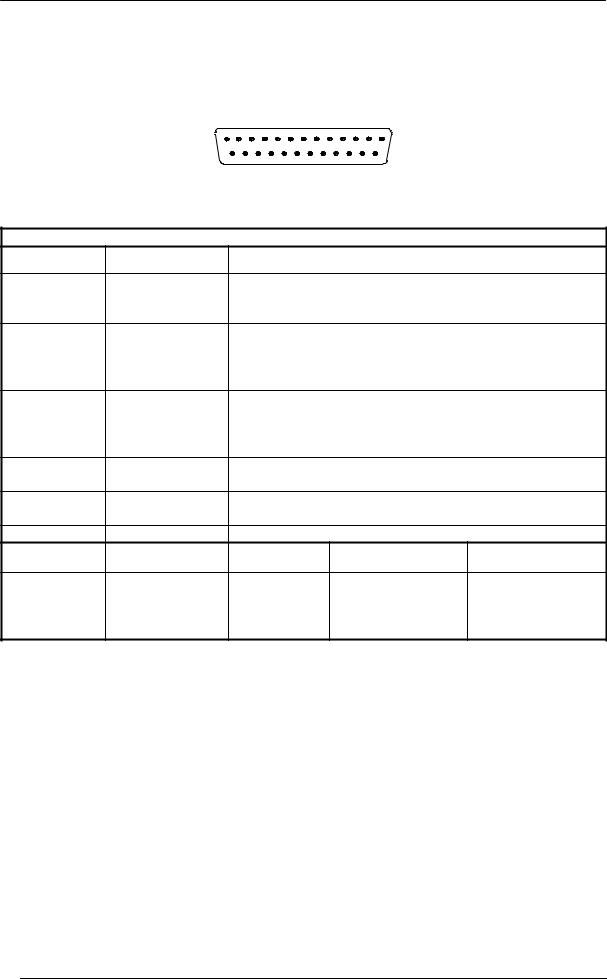
25-pin Connector Pinout for DS4800
The table below gives the pinout of the 25-pin male D-sub connector for connection to the power supply and input/output signals. Use this pinout when the DS4800 reader is connected by means of the 25-pin connector:
|
1 |
|
13 |
|
|
|
14 |
25 |
|
||
|
Figure 2 - 25-pin Male D-sub Connector |
|
|||
|
25-pin D-sub male connector pinout |
|
|||
Pin |
Name |
Function |
|
|
|
13, 9 |
Vdc |
Power supply input voltage + |
|
||
25, 7 |
GND |
Power supply input voltage - |
|
||
1 |
CHASSIS |
Cable shield connected to chassis |
|
||
18 |
I1A |
External Trigger A (polarity insensitive) |
|
||
19 |
I1B |
External Trigger B (polarity insensitive) |
|
||
6 |
I2A |
Input 2 A (polarity insensitive) |
|
||
10 |
I2B |
Input 2 B (polarity insensitive) |
|
||
8 |
O1+ |
Output 1 + |
|
|
|
22 |
O1- |
Output 1 - |
|
|
|
11 |
O2+ |
Output 2 + |
|
|
|
12 |
O2- |
Output 2 - |
|
|
|
20 |
RX |
Auxiliary RS232 RX |
|
|
|
21 |
TX |
Auxiliary RS232 TX |
|
|
|
23 |
ID+ |
ID-NET™ network + |
|
|
|
24 |
ID- |
ID-NET™ network - |
|
|
|
14, 15, 16, 17 |
NC |
Not Connected |
|
|
|
Pin |
Name |
RS232 |
RS485 |
RS485 |
|
Full-Duplex |
Half-Duplex |
||||
|
|
|
|||
2 |
MAIN INTERFACE |
TX |
TX+ |
RTX+ |
|
3 |
RX |
*RX+ |
|
||
4 |
(SW SELECTABLE) |
RTS |
TX- |
RTX- |
|
5 |
|
CTS |
*RX- |
|
|
* Do not leave floating, see Reference Manual for connection details.
4
DS4800 QUICK GUIDE
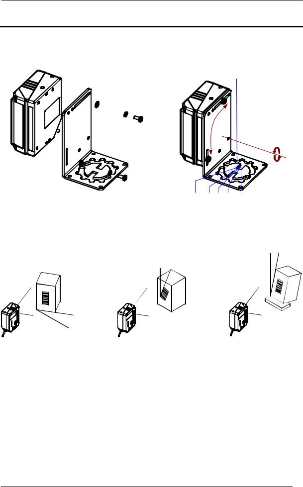
STEP 2 – MOUNT AND POSITION THE SCANNER
1.To mount the DS4800, use the mounting bracket to obtain the most suitable position for the reader as shown in the figures below.

 Skew
Skew
Pitch
-45° -15° 0° 15° 45°
Figure 3 - Positioning with Mounting Bracket
2.When mounting the DS4800 take into consideration these three ideal label position angles: Skew 15° to 30°, Tilt 0° and Pitch 0°.
P
T
S
Assure at least 15° |
Minimize |
Minimize |
Figure 4 –Skew, Tilt and Pitch Angles
3.Refer to the Reading Diagrams in the Appendix of this Quick Reference Guide to decide the distance your scanner should be positioned at.
5

DS4800 QUICK GUIDE
STEP 3 – FOCUS THE SCANNER
The reading distance depends on the focus distance of the scanner and should be set according to the application requirements. The Focus Position is set directly through the focus adjustment screw on the front panel of the scanner. This screw moves the internal lens of the scanner to change the focal length of the scanner. The setting is continuous but should not be set beyond the limits "Too Far" or "Too Near" which appear on the display at the extremes of the focus range. Although the scanner reads across the entire focus range, there are three guaranteed positions which correspond to the reading diagrams in the Appendix of this Quick Reference Guide.
1.Power up the scanner and wait for the power up sequence to finish. The alternating message on the display shows the mechanical Focus Position.
2.Using a screwdriver turn the focus adjustment screw in the desired direction clockwise (focus nearer to the scanner) or counterclockwise (focus farther from the scanner). The focus position in centimeters and inches is shown on the scanner display.
The value of the Focus Position can be stored in memory. If the mechanical position changes with respect to the value in memory, an alarm will be sent. See the Focus
Lock function in step 4, X-PRESS™ Configuration.
NOTE
As an additional visual aid during focusing, the indicator LEDs show the relative focus position as follows:
READY |
|
|
READY |
|
|
READY |
|
|
GOOD |
|
SETUP |
GOOD |
|
SETUP |
GOOD |
|
SETUP |
|
|
|
|
|
|
|||
TRIGGER |
|
LEARN |
TRIGGER |
|
LEARN |
TRIGGER |
|
LEARN |
|
|
|
|
|
|
|||
COM |
TEST |
COM |
TEST |
COM |
TEST |
|||
|
|
|
||||||
STATUS |
|
|
STATUS |
|
|
STATUS |
|
|
|
|
Î |
|
Í |
Î |
|
Í |
Î |
|
less than 30 cm |
|
30 cm |
|
32-38 cm |
|||
READY |
|
|
READY |
|
|
READY |
|
|
GOOD |
|
SETUP |
GOOD |
|
SETUP |
GOOD |
|
SETUP |
|
|
|
|
|
|
|||
TRIGGER |
|
LEARN |
TRIGGER |
|
LEARN |
TRIGGER |
|
LEARN |
|
|
|
|
|
|
|||
COM |
TEST |
COM |
TEST |
COM |
TEST |
|||
|
|
|
||||||
STATUS |
|
|
STATUS |
|
|
STATUS |
|
|
|
Í |
Î |
|
Í |
Î |
|
Í |
Î |
|
40 cm |
|
42-58 cm |
|
60 cm |
|||
READY
GOOD  SETUP
SETUP
TRIGGER LEARN
LEARN
COM  TEST
TEST
STATUS
Í
more than 60 cm
6
 Loading...