


 Loading...
DS2200
Reference Manual

DS2200
REFERENCE MANUAL

DATALOGIC S.p.A. Via Candini 2
40012 - Lippo di Calderara di Reno Bologna - Italy
DS2200 Reference Manual
Ed.: 4/2006
ALL RIGHTS RESERVED
Datalogic reserves the right to make modifications and improvements without prior notification.
Datalogic shall not be liable for technical or editorial errors or omissions contained herein, nor for incidental or consequential damages resulting from the use of this manual.
Product names mentioned herein are for identification purposes only and may be trademarks and or registered trademarks of their respective companies.
© Datalogic S.p.A. 1998 - 2006
21/04/06

CONTENTS
|
REFERENCES ............................................................................................. |
v |
|
Conventions .................................................................................................. |
v |
|
Reference Documentation ............................................................................ |
v |
|
Services and Support.................................................................................... |
v |
|
SAFETY PRECAUTIONS............................................................................ |
vi |
|
Laser Safety.................................................................................................. |
vi |
|
Power Supply.............................................................................................. |
viii |
|
WEEE Compliance ..................................................................................... |
viii |
|
GENERAL VIEW ......................................................................................... |
ix |
|
GUIDE TO INSTALLATION ......................................................................... |
x |
1 |
INTRODUCTION .......................................................................................... |
1 |
1.1 |
Product Description....................................................................................... |
1 |
1.1.1 |
Indicators ...................................................................................................... |
2 |
1.2 |
Model Description ......................................................................................... |
2 |
1.3 |
Accessories................................................................................................... |
3 |
2 |
INSTALLATION............................................................................................ |
4 |
2.1 |
Package Contents......................................................................................... |
4 |
2.2 |
Mechanical Installation.................................................................................. |
5 |
2.2.1 |
Mounting DS2200 ......................................................................................... |
6 |
2.3 |
Electrical Connections .................................................................................. |
7 |
2.3.1 |
Power Supply................................................................................................ |
8 |
2.3.2 |
Main Serial Interface - RS485 Half-Duplex ................................................... |
8 |
2.3.3 |
Auxiliary Interface - RS232 ........................................................................... |
9 |
2.3.4 |
Inputs .......................................................................................................... |
10 |
2.3.5 |
Outputs ....................................................................................................... |
11 |
2.4 |
Positioning .................................................................................................. |
11 |
2.5 |
Typical Layouts ........................................................................................... |
13 |
2.5.1 |
Point-to-Point .............................................................................................. |
13 |
2.5.2 |
RS485 Master/Slave ................................................................................... |
13 |
2.5.3 |
Multiplexer................................................................................................... |
15 |
3 |
READING FEATURES ............................................................................... |
16 |
3.1 |
Step-Ladder Mode ...................................................................................... |
16 |
3.2 |
Picket-Fence Mode ..................................................................................... |
17 |
3.3 |
Performance ............................................................................................... |
18 |
3.3.1 |
Raster ......................................................................................................... |
18 |
3.4 |
Reading Diagrams ...................................................................................... |
19 |
|
|
iii |

4 |
MAINTENANCE ......................................................................................... |
21 |
4.1 |
Cleaning...................................................................................................... |
21 |
5 |
TECHNICAL FEATURES........................................................................... |
22 |
|
GLOSSARY................................................................................................ |
24 |
|
INDEX......................................................................................................... |
28 |
iv

REFERENCES
CONVENTIONS
This manual uses the following conventions:
“User” or “Operator” refers to anyone using a DS2100A. “Device” refers to the DS2100A.
“You” refers to the System Administrator or Technical Support person using this manual to install, mount, operate, maintain or troubleshoot a DS2100A.
REFERENCE DOCUMENTATION
The documentation related to the DS2100A management is listed below:
•INT-30 20 mA Current Loop Interface Board for C-Box 100
•C-BOX 100 Installation Manual
•C-BOX 300/310 Installation Manual
•C-BOX 400/410 Installation Manual
•WinHost Help On Line
SERVICES AND SUPPORT
Datalogic provides several services as well as technical support through its website. Log on to www.datalogic.com and click on the links indicated for further information including:
•PRODUCTS
Search through the links to arrive at your product page where you can download specific Manuals and Software & Utilities
•SERVICES & SUPPORT
-Datalogic Services - Warranty Extensions and Maintenance Agreements
-Authorised Repair Centres
•CONTACT US
E-mail form and listing of Datalogic Subsidiaries
v
SAFETY PRECAUTIONS
LASER SAFETY
The following information is provided to comply with the rules imposed by international authorities and refers to the correct use of the DS2200 scanner.
Standard Regulations
This scanner utilizes a low-power laser diode. Although staring directly at the laser beam momentarily causes no known biological damage, avoid staring at the beam as one would with any very strong light source, such as the sun. Avoid that the laser beam hits the eye of an observer, even through reflective surfaces such as mirrors, etc.
This product conforms to the applicable requirements of both EN 60825-1 and CDRH 21 CFR 1040 at the date of manufacture. The scanner is classified as a Class 2 laser product according to EN 60825-1 regulations and as a Class II laser product according to CDRH regulations.
There is a safety device which allows the laser to be switched on only if the motor is rotating above the threshold for its correct scanning speed.
The laser beam can be switched off through a software command (see WinHost Help On Line or the "Command Strings for DS2200" file in the DS2200 directory).
Use of controls or adjustments or performance of procedures other than those specified herein may result in exposure to hazardous visible laser
light.
WARNING
The laser light is visible to the human eye and is emitted from the window on the side of the scanner (Figure A, 2).
vi
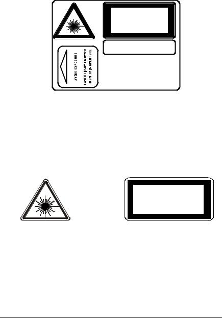
The warning label indicating exposure to laser light and the device classification is applied onto the body of the scanner (Figure A, 8):
LASER LIGHT
DO NOT STARE INTO BEAM
CLASS 2 LASER PRODUCT
MAX. OUTPUT RADIATION 1 mW
EMITTED WAVELENGTH 630~680 nm
TO EN 60825-1:2001
CAUTION-CLASS 3B LASER LIGHT
WHEN OPEN AVOID EXPOSURE TO BEAM
This product conforms to the applicable requirements of 21CFR1040 at the date of manufacture.
DATALOGIC S.p.A. Via Candini, 2 40012 Calderara di Reno - Bologna - Italy
Warning and Device Class Label
For installation, use and maintenance it is not necessary to open the scanner.
The laser diode used in this device is classified as a Class 3B laser product according to EN 60825-1 regulations and as a Class IIIb laser product according to CDRH regulations. As it is not possible to apply a classification label on the laser diode used in this device, the following label is reproduced here:
LASER LIGHT
AVOID EXPOSURE TO BEAM
CLASS 3B LASER PRODUCT
MAXIMUM OUTPUT RADIATION |
7 mW |
EMITTED WAVE LENGTH |
630 680 nm |
TO EN 60825-1 (2001) |
|
Laser Diode Class Label
Any violation of the optic parts in particular can cause radiation up to the maximum level of the laser diode (7mW at 630 680 nm).
vii

POWER SUPPLY
-This product is intended to be installed by Qualified Personnel only.
-DS2200 All Models:
This device is intended to be supplied either by a UL Listed NEC Class 2 power source, or a UL listed ITE Limited Power Source (LPS), rated 5Vdc, minimum 0.4A.
WEEE COMPLIANCE
viii

GENERAL VIEW
DS2200
6
5
4
3
2
7
1
8
|
|
Figure A |
|
1 |
Barcode Image Input Window |
5 |
Ext Trig LED |
2 |
Laser Beam Output Window |
6 |
TX Data LED |
3 |
Power On LED |
7 |
Mounting Holes |
4 |
Good Read LED |
8 |
Laser Warning and Device Class Label |
ix

GUIDE TO INSTALLATION
The following can be used as a checklist to verify all the necessary steps for complete installation of the DS2200 scanner.
1.Read all information in the section "Safety Precautions” at the beginning of this manual.
2.Correctly position and mount the scanner for barcode reading according to the information in par. 2.2, 2.4 and 3.4.
3.Provide correct system cabling according to the signals necessary (see all applicable sub-paragraphs under 2.3). See also sub-paragraphs under 2.5 for reference.
4.Install the Configuration Disk.
Upon successful completion of the installation, the readme.hlp file is opened, giving details about how to get started configuring your scanner.
See also the Guide to Rapid Configuration link.
Specific parameter details are available in the Help On Line.
Fine tuning of the scanner position for barcode reading can be accomplished using the Test Mode as described in WinHost.
NOTE
The installation is now complete.
x

INTRODUCTION |
1 |
|
1 INTRODUCTION
1.1PRODUCT DESCRIPTION
The DS2200 scanner is a cost effective barcode reader complete with decoder designed to satisfy demanding requirements associated with high performance scanning.
The DS2200 ultra compact dimensions, based on Datalogic's experience in miniaturized laser components, make the scanner's integration into automated equipment extremely easy.
The DS2200 is easily configurable by means of the Windows-based user-friendly WinHost utility program provided on diskette, or through ESC sequences via the serial interface.
Some of the main features of DS2200 are listed below:
•miniaturized dimensions
•scanning speed: 500 scans/sec.
•linear, raster and high optical resolution versions
•2 serial communication interfaces: RS232 + RS485 Half-Duplex
•reads all popular codes
•supply voltage: 5 Vdc
•test mode to verify the reading features and exact positioning of the scanner without the need for external tools
•programmable in 4 different operating modes to suit the most various barcode reading system requirements
•code verifier
•programmable input and output signals
•light source: solid state laser diode; the light emitted has a wave length of 630 680 nm. For laser safety precautions refer to the “Safety Precautions” section at the beginning of this manual
•low power consumption
•IP65 protection class of the enclosure; the reader is therefore suitable for industrial environments where high protection against harsh external conditions is required.
The laser beam output window is on the side of the scanner (Figure A, 2).
1
Loading...