


 Loading...
C-BOX 150
Installation Manual

Datalogic Automation S.r.l. Via S. Vitalino 13
40012 - Lippo di Calderara di Reno Bologna - Italy
C-BOX 150
Ed.: 07/2007
ALL RIGHTS RESERVED
Datalogic reserves the right to make modifications and improvements without prior notification.
Datalogic shall not be liable for technical or editorial errors or omissions contained herein, nor for incidental or consequential damages resulting from the use of this material.
Product names mentioned herein are for identification purposes only and may be trademarks and or registered trademarks of their respective companies.
© Datalogic Automation S.r.l. 2002-2007
821001271 (Rev. B)

CONTENTS
1 |
INTRODUCTION .......................................................................................... |
1 |
1.1 |
Product Description....................................................................................... |
1 |
1.2 |
C-BOX 150 Compatible Devices................................................................... |
2 |
2 |
INSTALLATION............................................................................................ |
3 |
2.1 |
Package Contents......................................................................................... |
3 |
2.2 |
Opening the Device ...................................................................................... |
4 |
2.3 |
Mechanical Installation.................................................................................. |
5 |
2.4 |
Electrical Connections and Hardware Setup................................................. |
7 |
2.4.1 |
Power Supply................................................................................................ |
8 |
2.4.2 |
System Wiring............................................................................................... |
9 |
2.4.3 |
Scanner Chassis Grounding Jumper Settings ............................................ |
12 |
2.4.4 |
Scanner Selection....................................................................................... |
12 |
2.4.5 |
RS485 Bus Termination.............................................................................. |
13 |
2.4.6 |
Powering C-BOX 150 From A Scanner....................................................... |
13 |
2.4.7 |
OM4000 Jumper Settings ........................................................................... |
14 |
2.4.8 |
Configuration Switch And 9-Pin Internal Connector .................................... |
14 |
2.5 |
Operating Modes ........................................................................................ |
16 |
2.5.1 |
GET/TEST/SEND Functions ....................................................................... |
16 |
2.5.2 |
LED Indicators ............................................................................................ |
18 |
2.6 |
Typical Layouts ........................................................................................... |
20 |
2.6.1 |
1000, 2000A/N, 4000 Family Scanners ...................................................... |
20 |
2.6.2 |
2000N Family Scanners.............................................................................. |
21 |
2.6.3 |
6000, 8000 Family Scanners ...................................................................... |
22 |
2.7 |
Scanner Replacement ................................................................................ |
23 |
3 |
TECHNICAL FEATURES........................................................................... |
24 |
iii
SAFETY PRECAUTIONS
POWER SUPPLY
ATTENTION: READ THIS INFORMATION BEFORE INSTALLING THE PRODUCT
- This product is intended to be installed by Qualified Personnel only.
The C-BOX 150 is intended to be supplied either by a UL Listed NEC Class 2 power source, or a UL Listed ITE Limited Power Source (LPS), rated 10-30 V dc, minimum 0.5 A.
The overall value of power consumption of the system (C-BOX 150 + scanner) is given by adding the scanner power consumption to that of the C-BOX 150. Refer to the manual of
CAUTION the connected scanner for details about minimum/maximum supply voltage and power consumption.
See par. 2.4.1 for correct power supply connections.
CE COMPLIANCE
Warning: This is a Class A product. In a domestic environment this product may cause radio interference in which case the user may be required to take adequate measures.
WEEE COMPLIANCE
ENGLISH
Information for the user in accordance with the European Commission Directive 2002/96/EC
At the end of its useful life, the product marked with the crossed out wheeled wastebin must be disposed of separately from urban waste.
Disposing of the product according to this Directive:
•avoids potentially negative consequences to the environment and human health which otherwise could be caused by incorrect disposal
•enables the recovery of materials to obtain a significant savings of energy and resources.
For more detailed information about disposal, contact the supplier that provided you with the product in question or consult the dedicated section at the website www.automation.datalogic.com.
iv

ITALIANO
Informazione degli utenti ai sensi della Direttiva Europea 2002/96/EC
L’apparecchiatura che riporta il simbolo del bidone barrato deve essere smaltita, alla fine della sua vita utile, separatamente dai rifiuti urbani.
Smaltire l’apparecchiatura in conformità alla presente Direttiva consente di:
•evitare possibili conseguenze negative per l’ambiente e per la salute umana che potrebbero invece essere causati dall’errato smaltimento dello stesso;
•recuperare materiali di cui è composto al fine di ottenere un importante risparmio di energia e di risorse.
Per maggiori dettagli sulle modalità di smaltimento, contattare il Fornitore dal quale è stata acquistata l’apparecchiatura o consultare la sezione dedicata sul sito www.automation.datalogic.com.
DEUTSCH
Benutzerinformation bezüglich Richtlinie 2002/96/EC der europäischen Kommission
Am Ende des Gerätelebenszyklus darf das Produkt nicht über den städtischen Hausmüll entsorgt werden. Eine entsprechende Mülltrennung ist erforderlich.
Beseitigung des Produkts entsprechend der Richtlinie:
•verhindert negative Auswirkungen für die Umwelt und die Gesundheit der Menschen
•ermöglicht die Wiederverwendung der Materialien und spart somit Energie und Resourcen
Weitere Informationen zu dieser Richtlinie erhalten sie von ihrem Lieferanten über den sie das Produkt erworben haben, oder besuchen sie unsere Hompage unter www.automation.datalogic.com.
FRANÇAIS
Information aux utilisateurs concernant la Directive Européenne 2002/96/EC
Au terme de sa vie utile, le produit qui porte le symbole d'un caisson à ordures barré ne doit pas être éliminé avec les déchets urbains.
Éliminer ce produit selon cette Directive permet de:
•éviter les retombées négatives pour l'environnement et la santé dérivant d'une élimination incorrecte
•récupérer les matériaux dans le but d'une économie importante en termes d'énergie et de ressources
Pour obtenir des informations complémentaires concernant l'élimination, veuillez contacter le fournisseur auprès duquel vous avez acheté le produit ou consulter la section consacrée au site Web www.automation.datalogic.com.
ESPAÑOL
Información para el usuario de accuerdo con la Directiva Europea 2002/96/CE
Al final de su vida útil, el producto marcado con un simbolo de contenedor de bassura móvil tachado no debe eliminarse junto a los desechos urbanos.
Eliminar este producto de accuerdo con la Directiva permite de:
•evitar posibles consecuencias negativas para el medio ambiente y la salud derivadas de una eliminación inadecuada
•recuperar los materiales obteniendo así un ahorro importante de energía y recursos
Para obtener una información más detallada sobre la eliminación, por favor, póngase en contacto con el proveedor donde lo compró o consultar la sección dedicada en el Web site www.automation.datalogic.com.
v
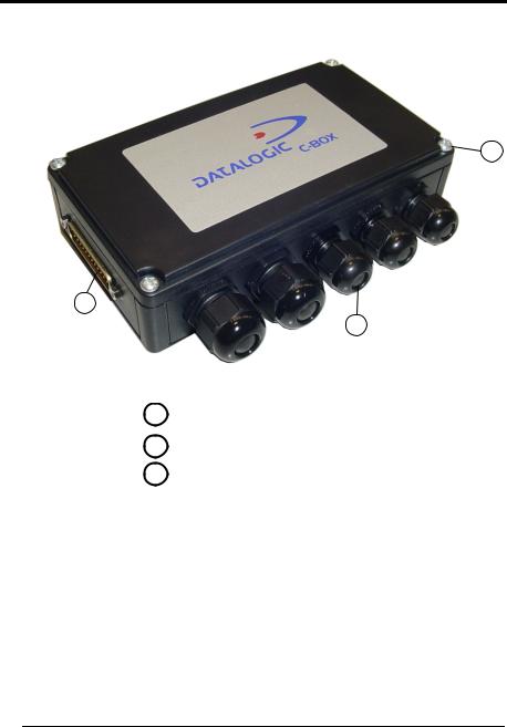
GENERAL VIEW
C-BOX 150
3
1
2
Figure A
125-pin scanner connector
2Compression connectors
3Cover screws (4)
vi

C-BOX 150
3 |
4 |
5 |
6 |
7 |
8 |
9 |
10 |
11 |
|
|
|
|
|
|
|
|
12 |
2 |
|
|
|
|
|
|
|
13 |
|
|
|
|
|
|
|
|
14 |
 15
15
1
16
17
18
|
Figure B - Bottom Inside |
||
1 |
Power on switch |
10 |
INT-30 power connector |
2 |
Chassis grounding jumper |
11 |
Auxiliary port connector |
3 |
Power polarity error LED (red) |
12 |
OM4000 jumpers |
4 |
RS485 Bus termin.switch |
13 |
Warning LED (red) |
5 |
Scanner selection switch |
14 |
Status LED |
6 |
Power on LED (green) |
15 Spring clamp terminal blocks |
|
7 |
GET button |
16 Tx LED |
|
8 |
TEST button |
17 |
Configuration switch |
9 |
SEND button |
18 |
Power source jumper |
vii

GUIDE TO INSTALLATION
The following can be used as a checklist to verify all of the steps necessary for complete installation of the C-BOX 150.
1)Read all information in the section "Safety Precautions" at the beginning of this manual.
2)Correctly position and mount the C-BOX 150 within the reach of the barcode scanner cable, according to the information in paragraph 2.3.
3)Make all electrical connections according to your application. See par. 2.4 and 2.6.
Further typical layouts are given in the Scanner Reference Manual.
4)Set all the proper configuration jumpers and switches according to your application.
See all sub-paragraphs under 2.4.
5)Connect the scanner to the C-BOX 150.
6)Switch-on the system.
7)Wait until the Warning Led (WL, red) is switched off.
8)Through the internal 9-pin male connector, (it carries the Scanner Aux. Serial Port signals), configure the scanner according to your specific application using either the Genius™ or WinHost™ software configuration tool, see par. 1.2 for program compatibility.
9)Force the 'Get Scanner Configuration' procedure using the internal keys (see paragraph 2.5.1).
10)Wait until the Warning Led (WL, red) is switched Off.
Now the C-BOX 150 contains the scanner configuration.
The installation is complete.
viii

INTRODUCTION |
1 |
|
1 INTRODUCTION
1.1PRODUCT DESCRIPTION
The C-BOX 150 is a connection box which can be used as an accessory to several Datalogic family scanners.
Its main feature is to make the substitution of a Datalogic scanner in an installation plain and easy.
To achieve this goal the C-BOX 150 provides the GET command to pass the connected scanner’s configuration to the C-BOX 150 non volatile memory. The SEND command allows a previously saved configuration to be transferred from the C-BOX 150 to the scanner.
By default, at every power-on, the C-BOX 150 automatically sends the configuration stored in its memory to the connected scanner. Therefore the substituted scanner will be correctly configured.
The C-BOX 150 allows you to perform the following functions:
•Facilitate the connection of the scanner signals using a spring clamp connector.
•Get the scanner configuration and store it in memory.
•Force the scanner to the Test operating mode.
•Send the configuration stored in memory to the scanner.
The C-BOX 150 mechanical dimensions are 161 x 114.5 x 40 mm (6.34 x 4.51 x 1.57 in.). The C-BOX 150 weighs about 410 g (14.48 oz).
Electrical connection is provided through spring clamp terminal blocks inside the C- BOX 150.
The scanner is connected to the C-BOX 150 through a 25-pin connector placed on the left side of the housing.
A 9-pin connector placed inside the C-BOX 150 facilitates connection between an external PC and the auxiliary serial interface of the scanner.
1

1 |
C-BOX 150 |
|
1.2C-BOX 150 COMPATIBLE DEVICES
The C-BOX 150 can be connected to the following scanners through the 25-pin connector illustrated in Figure A.
Scanner |
Configuration Tool |
DS1100 * |
WinHost™ |
DS2100A |
WinHost™ |
DS2100N |
Genius™ |
DS2200 * |
WinHost™ |
DS2400A |
WinHost™ |
DS2400N |
Genius™ |
DS4600A |
WinHost™ |
DS6X00 |
Genius™ |
DX6400 |
Genius™ |
DS8100A |
Genius™ |
DX8200A |
Genius™ |
*10 and 30 Vdc versions only
2
INSTALLATION |
2 |
|
2 INSTALLATION
2.1PACKAGE CONTENTS
Verify that the C-BOX 150 and all the parts supplied with the equipment are present and intact when opening the packaging; the list of parts includes:
1)C-BOX 150
2)Installation manual
3)C-BOX 150 configuration CD-ROM
4)2 mounting screws
5)Grounding cable
2
1
3
4
5
Figure 1 - C-BOX 150 Package Contents
3
Loading...