


Owner’s Use and Care Guide Guide d’utilisation et soins de Propriètaire
Model • Modèle
DPAC 11010
CAUTION: Read and follow all safety rules and operating instructions before first use of this product.
MISE EN GARDE:
Veuillez lire attentivement les consignes de sécurité et les directives d’utilisation avant l’utilisation de ce produit.
PORTABLE AIR CONDITIONER |
|
Table of Contents . . . . . . . . . . . . . . . . . . . . . . . . . . . . . . . . . . . . . . . . . |
1 |
CLIMATISEUR PORTATIF |
|
Table des Matières . . . . . . . . . . . . . . . . . . . . . . . . . . . . . . . . . . . . . . . . |
13 |
KEEP THESE INSTRUCTIONS FOR FUTURE REFERENCE: If the unit changes ownership, be sure this manual accompanies the unit.
CONSERVER CES INSTRUCTIONS POUR CONSULTATION ULTÉRIEURE: En cas de revente du l’appareil, ce manuel doit être inclus avec l’appareil.
Danby Products Ltd, PO Box 1778, Guelph, Ontario Canada N1H 6Z9
Danby Products Inc, PO Box 669, Findlay, Ohio USA 45839-0669
Version 2.1.09 JF

TABLE OF CONTENTS
UNIT SPECIFICATIONS . . . . . . . . . . . . . . . . . . . . . . . . . . . . . . . . . |
. 2 |
PART IDENTIFICATION . . . . . . . . . . . . . . . . . . . . . . . . . . . . . . . . . . |
3 |
IMPORTANT SAFETY INFORMATION |
|
Electrical Specifications . . . . . . . . . . . . . . . . . . . . . . . . . . . . . . . . . . . . . . . |
3 |
Energy Saving Tips . . . . . . . . . . . . . . . . . . . . . . . . . . . . . . . . . . . . . . . . . . . . . |
4 |
INSTALLATION . . . . . . . . . . . . . . . . . . . . . . . . . . . . . . . . . . . . . . . |
5 |
Window Kit Installation . . . . . . . . . . . . . . . . . . . . . . . . . . . . . . . . . . . . . . . |
6 |
OPERATION |
|
Remote Control . . . . . . . . . . . . . . . . . . . . . . . . . . . . . . . . . . . . . . . . . . . . . |
7 |
LCD Display . . . . . . . . . . . . . . . . . . . . . . . . . . . . . . . . . . . . . . . . . . . . . . . . . . |
7 |
Air Conditioning . . . . . . . . . . . . . . . . . . . . . . . . . . . . . . . . . . . . . . . . . . . . . |
8 |
Dehumidifier . . . . . . . . . . . . . . . . . . . . . . . . . . . . . . . . . . . . . . . . . . . . . . . . . . |
9 |
Fan . . . . . . . . . . . . . . . . . . . . . . . . . . . . . . . . . . . . . . . . . . . . . . . . . . . . . . . |
9 |
Heat . . . . . . . . . . . . . . . . . . . . . . . . . . . . . . . . . . . . . . . . . . . . . . . . . . . . . . |
10 |
Auto Timer . . . . . . . . . . . . . . . . . . . . . . . . . . . . . . . . . . . . . . . . . . . . . . . . . |
11 |
Clock Set . . . . . . . . . . . . . . . . . . . . . . . . . . . . . . . . . . . . . . . . . . . . . . . . . |
11 |
CARE AND MAINTENANCE . . . . . . . . . . . . . . . . . . . . . . . . . . . . |
12 |
TROUBLESHOOTING . . . . . . . . . . . . . . . . . . . . . . . . . . . . 13
Warranty . . . . . . . . . . . . . . . . . . . . . . . . . . . . . . . . . . . . . . . . . . . . . . . . . 14
1

WELCOME
Thank you for choosing a Danby appliance to provide you and your family with all of the “Home Comfort” requirements of your home, cottage, or office. This Owner’s Use and Care Guide will provide you with valuable information necessary for the proper care and maintenance of your new appliance. If properly maintained, your Danby appliance will give you many years of trouble free operation. Please take a few moments to read the instructions thoroughly and familiarize yourself with all of the operational aspects of this appliance.
Your Danby Portable Air-Conditioner is a multi-functional room air-exchanging, air-processing appliance, designed to offer you the functions of; Air Conditioning, Dehumidifying, and Independent Fan. Each individual mode is featured with “oscillating” air swing capabilities. This unit can be conveniently moved from room to room within your home and set up in just minutes. Imagine the convenience of 4 Season Home Comfort at your fingertips, anywhere,
anytime.
For easy reference, may we suggest you attach a copy of your sales slip/receipt to this page, along with the following information, located on the manufacturers nameplate on the rear panel of the unit.
Model Number:
Serial Number:
Date of Purchase:
This information will be necessary if your unit requires servicing and/or for general inquiries. To contact a Customer Service Representative, call Danby TOLL FREE:
Tel: 1-800-26-

 (1-800-263-2629)
UNIT SPECIFICATIONS
|
|
|
|
|
|
|
|
|
|
Model Number |
DPAC11010 |
|
|
|
|
|
Cooling Capacity |
12000Btu/h |
|
|
|
|
|
Noise Level |
52.4dB |
|
|
|
|
|
Fan Speeds |
3 |
|
|
|
|
|
Airflow CFM High/Medium/Low |
486 / 426 / 366 |
|
|
|
|
|
Power Source |
115 V - 60 Hz |
|
|
|
|
|
Refrigerant |
R410A |
|
|
|
|
|
Unit Weight |
35kg (77 lb.) |
|
|
|
|
|
Unit Dimensions (inches) W x D x H |
197/10 x 161/3 x 323/4 |
|
|
|
|
|
Unit Dimensions (mm) W x D x H |
500 x 415 x 830 |
|
|
|
|
|
Remote Control |
Yes |
|
|
|
|
|
Time of Day Clock |
No |
|
|
|
|
|
Auto-Timer |
Yes |
|
|
NOTE: Continuing research results in steady improvement. Therefore, this information and these specifications are subject to change without notice.
2
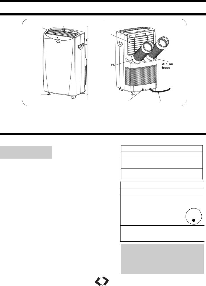
UNIT PARTS IDENTIFIED
Control Panel
Air outlet |
|
|
|
|
|
|
|
|
Air intake |
|
|
||||
|
|
|
|
||||
|
|
(evaporator) |
|
|
|||
|
|
|
|
|
|
|
|
|
|
|
|
|
|
|
|
Signal |
Handle |
|
|
|
|
||
Hole |
|
|
|
|
|||
receptor |
|
|
|
|
|||
|
|
|
|
|
|
|
|
|
|
|
|
|
|
|
|
|
|
|
|
|
|
||
|
|
|
|
|
Air outlet |
||
|
|
|
Air intake |
|
|
||
|
|
|
|
hose |
|
|
hose |
|
|
|
|
|
|
|
|
|
|
|
|
|
|
|
|
Castor
Water outlet drain |
Power supply cord |
|
|
|
|
IMPORTANT SAFETY INFORMATION
READ ALL SAFETY INFORMATION BEFORE USING
ELECTRICAL
SPECIFICATIONS
1)All wiring must comply with local and national electrical codes and be installed by a qualified electrician. If you have any questions regarding the following instructions, contact a qualified electrician.
2)Check available power supply and resolve any wiring problems BEFORE installation and operation of this unit.
3)This appliance draws 10.8 nameplate amps under Cooling Mode and may be used in any properly wired, general purpose 15 amp household grounded receptacle.
4)For your safety and protection, this unit is grounded through the power cord plug when plugged into a matching wall outlet. If you are not sure whether the wall outlets in your home are properly grounded, please consult a qualified electrician. DO NOT USE PLUG ADAPTERS OR EXTENSION CORDS WITH THIS UNIT. If it is necessary to use an extension cord with this unit, use an approved “air conditioner” extension cord only (available at most local hardware stores).
5)The manufacturers nameplate is located on the rear panel of the unit, and contains electrical and other technical data specific to this unit.
6)To avoid the possibility of personal injury, always disconnect the power supply to the unit before installing and/or servicing.
TABLE 1
Suggested Individual Branch Circuit
Nameplate Amps |
*AWG Wire Size |
10.8 |
16 |
AWGAmerican Wire Gauge
*Based on copper wire at 105°C temperature rating.
TABLE 2
Receptacle and Fuse Types
Rated Volts |
125 |
|
|
Amps |
15 |
|
|
Wall Outlet |
|
|
|
|
|
|
|
Fuse Size |
15 |
|
|
||
|
|
|
|
|
|
Time Delay Fuse |
Plug Type |
||||
(or Circuit Breaker) |
|
|
|
|
|
CAUTION: Do not leave this unit unattended in a space where people or animals cannot react to a failed unit are located. A failed unit can cause extreme overheating or death in such an enclosed, unattended space.
3

|
|
|
IMPORTANT SAFETY INFORMATION |
|
|
|
|
|
|
POWER |
The power cord supplied with this air conditioner contains a device that senses damage to |
SUPPLY CORD |
the power cord. To test if your power cord is working properly, you must do the following: |
|
|
1)Connect the power supply cord to an electrical outlet.
2)The power supply cord has two buttons located on the head of the plug. One button is marked “TEST”, and the other is marked “RESET”. Press the “TEST” button; you will hear a click as the “RESET” button pops out.
3)Press the “RESET” button; you will hear a click as the button engages.
4)The power supply cord is now energized and supplying electricity to the air conditioner (on some products this is also indicated by a light on the plug head).
NOTE: The power cord supplied with this air conditioner contains a current leakage detection device designed to reduce the risk of fire. In the event the power supply cord is damaged, it cannot be repaired and must be replaced with a new cord from the product manufacturer.
•Under no circumstances should this device be used to turn the unit on or off.
•The “RESET” button must always be pushed in (engaged) for correct operation.
•The power supply cord must be replaced if it fails to reset when the “TEST” button is pushed in.
ENERGY- |
Your Danby appliance is designed to be highly efficient in energy savings. Follow |
|
SAVING TIPS |
||
these recommendations for greater efficiency. |
||
|
|
1)Select a thermostat setting that suits your comfort needs and leave at that chosen setting.
2)The air filter is very efficient in removing airborne particles. Keep the air filter clean at all times.
3)Use drapes, curtains or shades to keep direct sunlight from penetrating and heating room, but do not allow drapes or curtains to obstruct the air flow around the unit.
4)Start your air conditioner before the outdoor air becomes hot and uncomfortable, to avoid an initial period of discomfort while the unit is cooling off the room. Use of the automatic start/stop programmable TIMER feature can be a major asset in this regard if utilized to the fullest extent.
5)When outdoor temperatures are cool enough, turn the air conditioner off and use the FAN MODE on HIGH, MED, or LOW. This circulates indoor air, providing some cooking comfort while utilizing less electricity.
4

INSTALLATION
ELECTRIC SHOCK HAZARD: To avoid
WARNING the possibility of personal injury, disconnect power to the unit before installing or servicing.
INSTALLATION ACCESSORIES (FIG. 1)
Flexible Exhaust Hose (13cm) & Exhaust nozzle connector (2 pcs)... from 17 7/10 (45cm) up to 53 1/6”(135cm)
Adjustable window door slider kit (3 pcs)..... from 28
1/3”(72cm) up to 80” (203cm)
Fixture..... |
(2 pcs) |
Screws...(8 pcs)
NOTE: The exhaust/window kit must be installed at all times when the unit is operating under AIR CONDITIONING mode.
Fig. 1 INSTALLATION ACCESSORIES
Flexible Exhaust Hose |
Fixture |
Exhaust Nozzle
Connector
Screws
Adjustable Window Slider Kit:
28 1/3” (72cm)- 80” (203cm)
IMPORTANT
There should be at least 11.8” (30cm) clearance between the unit and any other objects or building structures, and should be installed on a level surface. The unit does not have to be vented outside during Dehumidifying or Fan Only mode operation.
INSTRUCTIONS FOR ASSEMBLING THE WINDOW ADAPTER KIT (FIG. 2).
a)Insert tube adapters through the back of the window panel.
b)Secure each tube adapter with four screws through the front of the window panel.
c)Insert window panel extensions into the window panel. Lightly tighten the screws in the window panel to hold the extensions in place.
Fig. 2 |
|
Back of |
|
|
Window Panel |
|
|
Tube Adapters
WINDOW KIT |
Your window kit has been designed to fit most standard “vertical”/”horizontal” windows up to |
INSTALLATION |
a maximum height of 80” (203cm).For vertical window applications, multi lock positions are |
provided on the edge of each slider section to secure each sliding section together. |
1) Select a suitable location, making sure you have access to an electrical outlet.
2)Install the flexible hose to the rear side of the unit. Insert the hose collar on top of the exhaust opening and twist to lock into position.
3)Install the adjustable Window Slider Kit as required (see Fig. 3a & 3b).
4)Install the opposite end of the flexible exhaust hose into the window exhaust adapter.
5)Install the window exhaust adapter into the opening in the slider section, making sure the window slider sections are secure.
6)Plug the unit into a 115V/60Hz grounded electrical outlet.
|
|
|
HORIZONTAL |
|
|
|
|
Fig. 3a |
|
Window Slider Kit: |
|
|
Fig. 3b |
||
|
|
|
Min.: 26 5/8” (67.5cm) |
|
|
|
|
|
|
|
Max.: 80” (203cm) |
|
|
|
|
|
|
|
|
|
|
|
|
|
|
|
|
|
|
|
|
|
|
|
|
|
|
|
|
|
|
|
|
|
|
|
|
VERTICAL
Window Slider Kit:
Min.: 26 5/8” (67.5cm)
Max.: 80” (203cm)
5
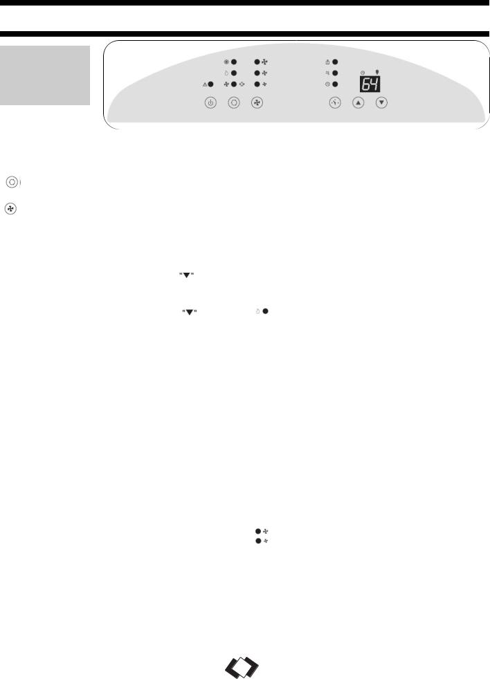
OPERATING INSTRUCTIONS
FEATURES
OF THE
CONTROL
PANEL
KEY PAD FUNCTIONS
 POWER SWITCH:Turns unit ON/OFF
MODE: Allows you to scroll through and select desired operating mode.
FAN: Select from three different fan settings;
High, Medium, and Low.
 AUTO-TIMER
AUTO-TIMER Adjust:
Auto off- With machine in running mode, press timer button to set timer control. Press  buttons to select number of hours you would like the unit to run before it automatically shuts off.
Auto on- With machine in stand by mode, press timer button to set timer control. Press  buttons to select number of hours before the unit automatically starts running in air conditionning mode.
NOTE: The time is adjustable between 1-24 hours.
TEMPERATURE Adjust:
•Used for adjusting the thermostat.
•The default display is room temperature.
•In cooling mode, when 
 button is pressed, the set temperature is displayed and may be adjusted. After 15 seconds the display will revert back to room temperature. Temperature is only adjustable in cool mode.
NOTE: By pressing both  buttons at the same time for more than 3 seconds, the display will toggle between Celsius and Fahrenheit.
STATUS DISPLAY
 Warning Light
Condensed water may accumulate in the unit. If the internal tank becomes full, the Warning signal in the LCD Display will light up and the unit will not operate until the unit has been drained.
 Timer & Temp. Display
 Room Temp.
 Temp. Set
 Timer Set
 MODE INDICATOR LIGHTS
Cooling Mode
When cool mode is selected, the indicator light will shine GREEN. During the cooling mode, the air is cooled and hot air is exhausted outside through the exhaust tube. Adjust fan speed to suit your desired comfort level.
Note: The air exchange h ose must vent outside the room when using cool mode.
Dehumidify Mode
When dehumidify mode is selected, the indicator light will shine ORANGE. Air is dehumidified as it passes through the unit, without being in full cooling mode. The fan will operate on med. speed. If room temperature is >25°C (77°F), fan speed can be adjusted; otherwise fan speed is fixed to “low”. Note: The warm air exchange hose must vent inside the room when using Dehumidify Mode, not outside as it does when cooling. If the unit is vented outside, some cooling will occur.
 Fan Mode
When fan mode is selected, the indicator will shine YELLOW. Air is circulated throughout the room with no cooling.
Note: The unit does not need to be vented in Fan mode.
• During Fan/Dehumidifier mode, the temperature cannot be set.
FAN SPEED INDICATOR LIGHTS
 High Fan
Medium Fan
Low Fan
NOTE: AFTER SWITCHING THE AIR CONDITIONER OFF, YOU MUST WAIT 3 MINUTES
BEFORE SWITCHING IT BACK ON AGAIN.
6
 Loading...