


Daikin UFH-BM, UFH-UM, UFH-RMD2, UFH-RMD6, UFH-RD Operation manuals
...Installation and operating manual
RoCon UFH
UFH-BM
UFH-UM UFH-RMD2 UFH-RMD6 UFH-RD UFH-RMF2A UFH-RMF6A UFH-RFT
Installation and operating manual |
English |
Installationsund Betriebsanleitung |
Deutsch |
Manuel d'installation et de fonctionnement |
Français |
Montagehandleiding en gebruiksaanwijzing |
Nederlands |
Manuale d'installazione e d'uso |
Italiano |
12/2020
Installation and operating manual
RoCon UFH
Installation and operating manual |
English |
UFH-BM
UFH-UM
UFH-RMD2
UFH-RMD6
UFH-RD
UFH-RMF2A
UFH-RMF6A
UFH-RFT
12/2020

|
About these operating instructions |
EN |
|
||
|
|
|
1 About these operating instructions
These operating instructions describe the system "„RoCon UFH" for single room temperature control (also referred to as "product" in these operating instructions). These operating instructions are part of the product.
•You may only use the product if you have fully read and understood these operating instructions.
•Verify that these operating instructions are always accessible for any type of work performed on or with the product.
•Pass these operating instructions as well as all other product-related documents on to all owners of the product.
•If you feel that these operating instructions contain errors, inconsistencies, ambiguities or other issues, contact the manufacturer prior to using the product.
•The wireless system described in these instructions is only available in certain sales areas.
These operating instructions are protected by copyright and may only be used as provided for by the corresponding copyright legislation. We reserve the right to modifications.
The manufacturer shall not be liable in any form whatsoever for direct or consequential damage resulting from failure to observe these operating instructions or from failure to comply with directives, regulations and standards and any other statutory requirements applicable at the installation site of the product.
RoCon UFH |
2 |
|
Information on safety |
EN |
|
||
|
|
|
2 Information on safety
2.1Safety messages and hazard categories
These operating instructions contain safety messages to alert you to potential hazards and risks. In addition to the instructions provided in these operating instructions, you must comply with all directives, standards and safety regulations applicable at the installation site of the product. Verify that you are familiar with all directives, standards and safety regulations and ensure compliance with them prior to using the product.
Safety messages in these operating instructions are highlighted with warning symbols and warning words. Depending on the severity of a hazard, the safety messages are classified according to different hazard categories.

 DANGER
DANGER indicates a hazardous situation, which, if not avoided, will result in death or serious injury.
NOTICE
NOTICE indicates a hazardous situation, which, if not avoided, can result in equipment damage.
In addition, the following symbols are used in these operating instructions:
This is the general safety alert symbol. It alerts to injury hazards or equipment damage. Comply with all safety instructions in conjunction with this symbol to help avoid possible death, injury or equipment damage.
This symbol alerts to hazardous electrical voltage. If this symbol is used in a safety message, there is a hazard of electric shock.
RoCon UFH |
3 |

|
Information on safety |
EN |
|
||
|
|
|
2.2Intended use
This product may only be used to control the room temperature (heat/cool) of individual rooms with underfloor heating system.
The controller modules may only be used to control the thermostatic actuators via the signals of the associated room controllers and the base module.
Any use other than the application explicitly permitted in these operating instructions is not permitted and causes hazards.
Verify that the product is suitable for the application planned by you prior to using the product. In doing so, take into account at least the following:
•All directives, standards and safety regulations applicable at the installation site of the product
•All conditions and data specified for the product
•The conditions of the planned application
In addition, perform a risk assessment in view of the planned application, according to an approved risk assessment method, and implement the appropriate safety measures, based on the results of the risk assessment. Take into account the consequences of installing or integrating the product into a system or a plant.
When using the product, perform all work and all other activities in conjunction with the product in compliance with the conditions specified in the operating instructions and on the nameplate, as well as with all directives, standards and safety regulations applicable at the installation site of the product.
2.3Predictable incorrect application
The product must never be used in the following cases and for the following purposes:
•Hazardous area (EX)
-If the product is operated in hazardous areas, sparks may cause deflagrations, fires or explosions
•In conjunction with products which are used for health-saving or life-saving purposes or whose operation may incur hazards to humans, animals or property
RoCon UFH |
4 |

|
Information on safety |
EN |
|
||
|
|
|
2.4Qualification of personnel
Only appropriately trained persons who are familiar with and understand the contents of these operating instructions and all other pertinent product documentation are authorized to work on and with this product.
These persons must have sufficient technical training, knowledge and experience and be able to foresee and detect potential hazards that may be caused by using the product.
All persons working on and with the product must be fully familiar with all directives, standards and safety regulations that must be observed for performing such work.
2.5Personal protective equipment
Always wear the required personal protective equipment. When performing work on and with the product, take into account that hazards may be present at the installation site which do not directly result from the product itself.
2.6Modifications to the product
Only perform work on and with the product which is explicitly described in these operating instructions. Do not make any modifications to the product which are not described in these operating instructions.
RoCon UFH |
5 |
|
Transport and storage |
EN |
|
||
|
|
|
3 Transport and storage
The product may be damaged as a result of improper transport or storage.
NOTICE
INCORRECT HANDLING
•Verify compliance with the specified ambient conditions during transport or storage of the product.
•Use the original packaging when transporting the product.
•Store the product in a clean and dry environment.
•Verify that the product is protected against shocks and impact during transport and storage.
Failure to follow these instructions can result in equipment damage.
RoCon UFH |
6 |

|
Product description |
EN |
|
||
|
|
|
4 Product description
The single room temperature controller RoCon UFH is used to control the temperature in rooms with underfloor heating system (heating and cooling). The controller compares the actual temperature and the reference temperature and controls the volume flow of the heating water via the corresponding thermostatic actuators.
The room controllers measure the actual temperature in the corresponding rooms. The reference temperature is adjusted via the rotary knob of the corresponding room controllers.
The controller modules with 2 or 6 independent control circuits control the respective thermostatic actuators via the signals of the room controllers and the base module.
Th base module supplies the room controllers with 5 V DC and the thermostatic actuators with 230 V AC. The single room temperature controller RoCon UFH can be switched between heating and cooling via the base module. The control circuit pumps can be controlled via the base module.
The optional timer module features a hundred year calendar. The display shows the date, time and day of the week. The timer module features 2 independently programmable switching channels for temperature reduction. A total of 9 programmable memory blocks are available. The additional pump running time can be set via the timer module. The timer module has a valve and pump protection function.
The single room temperature controller consists of a base module, at least one room controller and at least one controller module. Multiple controller modules with 2 or 6 control circuits can be adapted.
The single room temperature controller RoCon UFH is available in 2 versions(1):
•Room controller and controller modules are interconnected by a cable.
•Room controllers and controller module are connected via EnOcean® wireless(1).
The single room temperature controller RoCon UFH is a modular system. The versions wired and wireless(1) can also be operated in mixed mode.
(1)The wireless system is only available in certain sales areas.
RoCon UFH |
7 |

|
Product description |
EN |
|
||
|
|
|
4.1Overview of the individual RoCon UFH components
Component |
Versions |
Explanation |
Ordering |
||
|
|
|
|
number |
|
Base module |
RoCon UFH- |
- |
175137 |
||
|
|
BM |
|
|
|
|
|
|
|
|
|
Timer module |
RoCon UFH- |
- |
175138 |
||
|
|
UM |
|
|
|
|
|
|
|
|
|
Room tempera- |
RoCon UFH-RD |
Wired |
175139 |
||
ture controller |
|
|
|
||
RoCon UFH- |
Wireless, temperature |
175142 |
|||
|
|
||||
|
|
RFT(1) |
|
|
|
Controller mod- |
RoCon UFH- |
Wired with 2 control circuits |
175141 |
||
ule |
RMD2 |
|
|
||
|
|
|
|
|
|
|
|
RoCon UFH- |
Wired with 6 control circuits |
175140 |
|
|
|
RMD6 |
|
|
|
|
|
|
|
|
|
|
|
RoCon UFH- |
With external antenna and 2 |
175144 |
|
|
|
RMF2A(1) |
control circuits |
|
|
|
|
RoCon UFH- |
With external antenna and 6 |
175143 |
|
|
|
RMF6A(1) |
control circuits |
|
|
|
|
|
|
|
|
(1) The wireless system is only available in certain sales areas.
RoCon UFH |
8 |
|
Product description |
EN |
|
||
|
|
|
4.2Overview
Base module RoCon UFH-BM
A. Fuse compartment
B. Operation mains voltage (LED green)
C. Operation 5 V (LED green)
D. Pump Heating (LED red)
E. Pump Cooling (LED blue)
F. Cooling (LED blue)
G. Input switchover Heating/
Cooling
H. Cascading output Heating/
Cooling
I. Relay contact pump Cooling
J. Relay contact pump Heating
K. Mains voltage 230 V AC
L. Timer module (optional)
Fig. 4-1: Front view base module
RoCon UFH |
9 |

|
Product description |
EN |
|
||
|
|
|
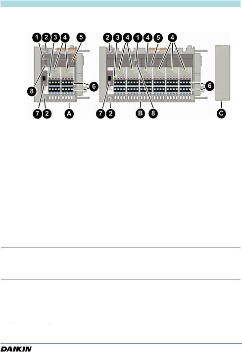
Controller modules wired
A.Controller module RoCon UFHRMD2
B.Controller module RoCon UFHRMD6
C.End cover
Fig. 4-2: Front view controller modules wired
1.Catch
2.Operation mains voltage (LED green)
3.Thermostatic actuator active (LED yellow)
4.Terminal block for room controller RoCon UFH-RD
5.Terminal block for thermostatic actuators
6.Fuse compartment
RoCon UFH |
10 |
|
Product description |
EN |
|
||
|
|
|
Controller modules wireless(1)
A.Controller module RoCon UFH RMF2A
B.Controller module RoCon UFH RMF6A
C.End cover
1.Teach-in key (LRN key)
2.Catch
3.Operation mains voltage (LED green)
4.Thermostatic actuator active (LED yellow)
5.Wireless module
6.Terminal block for thermostatic actuators
7.Fuse compartment
8.Reset button (CLR button)
Fig. 4-3: Front view controller modules wireless
Information
Additional information on planning (e.g. "range planning"), installation and operation of EnOcean® wireless systems can be found at www.enocean.com.
(1)The wireless system is only available in certain sales areas.
RoCon UFH |
11 |
|
Product description |
EN |
|
||
|
|
|
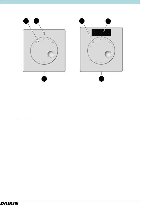
Room controller
1 |
2 |
1 |
3 |
A B
A.Room controller wired UFH-RD
B.Room controller wireless UFH-RFT(1)
1.Rotary knob for adjusting the reference temperature
2.LED red: Hearing LED blue: Cooling
3.Solar cell
Fig. 4-4: Front view room controller
(1)The wireless system is only available in certain sales areas.
RoCon UFH |
12 |
|
Product description |
EN |
|
||
|
|
|
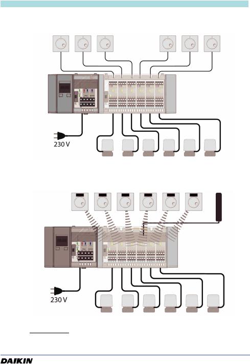
4.3Application examples
Fig. 4-5: Single room temperature controller-RoCon UFH with one controller module RoCon UFH-RMD6 wired and 6 room controllers RoCon UFH-RD
Fig. 4-6: Single room temperature controller RoCon UFH with one controller module RoCon UFH-RMF6A wireless(1) and 6 room controllers RoCon UFH-RFT(1)
(1) The wireless system is only available in certain sales areas.
RoCon UFH |
13 |

|
Product description |
EN |
|
|
|
|
|||
|
|
|
|
|
4.4 Technical data |
|
|
|
|
|
|
|
|
|
|
Parameter |
Base module RoCon UFH-BM |
|
|
|
General specifications |
|
|
|
|
|
|
|
|
|
Dimensions housing |
122 mm x 92 mm x 45 mm |
|
|
|
(W x H x D) |
|
|
|
|
|
|
|
|
|
Weight |
215 g |
|
|
|
|
|
|
|
|
Housing material |
PC/ABS |
|
|
|
|
|
|
|
|
Colour |
Light grey, similar to RAL 7047 |
|
|
|
|
|
|
|
|
Operating temperature range |
|
|
|
|
|
|
|
|
|
Ambient |
-20 °C ... +60 °C |
|
|
|
|
|
|
|
|
Storage |
-20 °C ... +60 °C |
|
|
|
|
|
|
|
|
Max. humidity |
Non-condensing |
|
|
|
|
|
|
|
|
Supply voltage |
|
|
|
|
|
|
|
|
|
Nominal voltage |
AC 230 V, 50 Hz to 60 Hz |
|
|
|
|
|
|
|
|
Nominal power (base module |
1 VA |
|
|
|
only) |
|
|
|
|
|
|
|
|
|
Mains fuse |
T 10 A |
|
|
|
|
|
|
|
|
Relay load |
Max. 230 V, max. 2 A, power factor > 0.6 |
|
|
|
|
|
|
|
|
Permissible cable type |
H03 VV-H2-F 2 x 0.75 mm² |
|
|
|
|
|
|
|
|
The following components may be connected to one product |
|
|
|
|
|
|
|
|
|
Controller modules sextuple |
Max. 3 |
|
|
|
|
|
|
|
|
Controller module dual |
Max. 9 |
|
|
|
|
|
|
|
|
Total number of control circuits |
Max. 18 |
|
|
|
|
|
|
|
|
Total number of thermostatic |
Max. 72 (see table 4-6) |
|
|
|
actuators |
|
|
|
|
|
|
|
|
|
Electrical safety |
|
|
|
|
|
|
|
|
|
Protection class (EN 60730-1) |
II |
|
|
|
|
|
|
|
|
Degree of protection |
IP 20 |
|
|
|
(EN 60529) |
|
|
|
|
|
|
|
|
Table 4-1: Technical specifications base module
RoCon UFH |
14 |

|
Product description |
|
EN |
|
|
|
|
|
|||
|
|
|
|
|
|
|
|
|
|
|
|
|
Parameter |
Controller module |
Controller module |
|
|
|
|
RoCon UFH-RMD2 |
RoCon UFH-RMD6 |
|
|
|
General specifications |
|
|
|
|
|
|
|
|
|
|
|
Dimensions housing |
73 mm x 92 mm x 45 mm |
162 mm x 92 mm x 45 mm |
|
|
|
(W x H x D) |
|
|
|
|
|
|
|
|
|
|
|
Weight |
130 g |
260 g |
|
|
|
|
|
|
|
|
|
Housing material |
PC/ABS |
|
||
|
|
|
|
|
|
|
Operating temperature range |
|
|
|
|
|
|
|
|
|
|
|
Ambient |
-20 °C … +60 °C |
|
||
|
|
|
|
||
|
Storage |
-20 °C … +60 °C |
|
||
|
|
|
|
||
|
Max. humidity |
Non-condensing |
|
||
|
|
|
|
|
|
|
Supply voltage |
|
|
|
|
|
|
|
|
|
|
|
Nominal voltage |
Via base module AC 230 V, DC 5 V |
|
||
|
|
|
|
|
|
|
Nominal power |
0.1 W |
0.3 W |
|
|
|
(controller module only) |
|
|
|
|
|
|
|
|
|
|
|
Fuse for thermostatic actu- |
T 1 A |
T 3.15 A |
|
|
|
ators |
|
|
|
|
|
|
|
|
|
|
|
Permissible cable type to |
H03 VV-H2-F 2 x 0.75 mm² |
|
||
|
thermostatic actuators |
|
|
|
|
|
|
|
|
||
|
Permissible cable type to |
J-Y (St) Y 2 x 2 x 0.6 mm2 |
|
||
|
the room temperature con- |
Wire colours: red, black, white, yellow |
|
||
|
trollers |
|
|
|
|
|
|
|
|
|
|
|
The following components may be connected to one controller module |
|
|||
|
|
|
|
|
|
|
Room controllers |
Max. 2 |
Max. 6 |
|
|
|
|
|
|
|
|
|
Thermostatic actuators |
Per control circuit up to 4 Daikin UFH-Sat8 |
|
||
|
|
|
|
|
|
|
Electrical safety |
|
|
|
|
|
|
|
|
|
|
|
Protection class |
|
II |
|
|
|
(EN 60730-1) |
|
|
|
|
|
|
|
|
||
|
Degree of protection |
IP 20 |
|
||
|
(EN 60529) |
|
|
|
|
|
|
|
|
|
|
|
Electromagnetic compatibility (EMC) |
|
|
|
|
|
|
|
|
|
|
|
Emitted interference/immu- |
EN 61326-1: 2013 |
|
||
|
nity |
|
|
|
|
|
|
|
|
|
|
Table 4-2: Technical specifications controller modules wired
RoCon UFH |
15 |

|
Product description |
|
EN |
|
|
|
|
|
|||
|
|
|
|
|
|
|
Controller module wireless(1) |
|
|
|
|
|
Parameter |
Controller module |
Controller module |
|
|
|
|
RoCon UFH RMF2A |
RoCon UFH RMF6A |
|
|
|
General specifications |
|
|
|
|
|
|
|
|
|
|
|
Dimensions (W x H x D) |
73 mm x 92 mm x 45 mm |
162 mm x 92 mm x 45 mm |
|
|
|
|
|
|
|
|
|
Weight |
130 g |
260 g |
|
|
|
|
|
|
|
|
|
Housing material |
PC/ABS |
|
||
|
|
|
|
|
|
|
Operating temperature range |
|
|
|
|
|
|
|
|
|
|
|
Ambient |
-20 °C … +60 °C |
|
||
|
|
|
|
||
|
Storage |
-20 °C … +60 °C |
|
||
|
|
|
|
||
|
Max. humidity |
Non-condensing |
|
||
|
|
|
|
|
|
|
Supply voltage |
|
|
|
|
|
|
|
|
|
|
|
Nominal voltage |
Via base module AC 230 V, DC 5 V |
|
||
|
|
|
|
|
|
|
Nominal power |
0.3 W |
0.5 W |
|
|
|
(controller module only) |
|
|
|
|
|
|
|
|
|
|
|
Fuse for thermostatic actua- |
T 1 A |
T 3.15 A |
|
|
|
tors |
|
|
|
|
|
|
|
|
|
|
|
Permissible cable type to |
H03 VV-H2-F 2 x 0.75 mm² |
|
||
|
thermostatic actuators |
|
|
|
|
|
|
|
|
|
|
|
The following components may be connected to one controller module |
|
|||
|
|
|
|
|
|
|
Room controllers |
Max. 2 |
Max. 6 |
|
|
|
|
|
|
|
|
|
Thermostatic actuators |
Per control circuit up to 4 Daikin UFH-Sat8 |
|
||
|
|
|
|
|
|
|
Electrical safety |
|
|
|
|
|
|
|
|
|
|
|
Protection class |
|
II |
|
|
|
(EN 60730-1) |
|
|
|
|
|
|
|
|
||
|
Degree of protection |
IP 20 |
|
||
|
(EN 60529) |
|
|
|
|
|
|
|
|
|
|
|
Electromagnetic compatibility (EMC) |
|
|
|
|
|
|
|
|
|
|
|
Emitted interference/immu- |
EN 61326-1:2013 |
|
||
|
nity |
|
|
|
|
|
|
|
|
|
|
|
EnOcean® wireless |
|
|
|
|
|
Radio Equipment Directive |
See declaration of conformity |
|
||
|
(RED) 2014/53/EU |
(enclosed with product) |
|
||
|
|
|
|
|
|
Table 4-3: Technical specifications controller modules wireless
(1)The wireless system is only available in certain sales areas.
RoCon UFH |
16 |

|
Product description |
|
EN |
|
|
|
|
|
|||
|
|
|
|
|
|
|
|
|
|
|
|
|
Parameter |
Room controller wired |
Room controller wire- |
|
|
|
|
RoCon UFH-RD |
less(1) RoCon UFH-RFT |
|
|
|
General specifications |
|
|
|
|
|
|
|
|
|
|
|
Dimensions (W x H x D) |
78 mm x 78 mm x |
78 mm x 82.5 mm x |
|
|
|
|
12.5 mm |
12.5 mm |
|
|
|
|
|
|
|
|
|
Weight |
30 g |
35 g |
|
|
|
|
|
|
|
|
|
Housing material |
PC |
|
||
|
|
|
|
||
|
Temperature adjustment |
8 °C… 30 C° |
|
||
|
range/ |
|
|
|
|
|
temperature measuring |
|
|
|
|
|
range |
|
|
|
|
|
|
|
|
||
|
Temperature reduction |
4K (only if higher than +12 °C) |
|
||
|
|
|
|
|
|
|
Operating temperature range |
|
|
|
|
|
|
|
|
|
|
|
Ambient |
-20 °C … +60 °C |
|
||
|
|
|
|
||
|
Storage |
-20 °C … +60 °C |
|
||
|
|
|
|
||
|
Max. humidity |
Non-condensing |
|
||
|
|
|
|
|
|
|
Humidity measurement |
|
|
|
|
|
|
|
|
|
|
|
Measuring range |
- |
0 % - 100 % room humidity |
|
|
|
|
|
|
|
|
|
Supply voltage |
|
|
|
|
|
|
|
|
|
|
|
Nominal voltage |
Via controller module |
Via solar cell or battery |
|
|
|
|
5 V DC |
(type 1632, 3 V DC) with |
|
|
|
|
|
illuminance < 200 lux |
|
|
|
|
|
|
|
|
|
Nominal power per room |
0.015 W |
Energy Harvesting |
|
|
|
controller |
|
|
|
|
|
|
|
|
|
|
|
Permissible cable type, |
J-Y (St) Y 2 x 2 x 0.6 mm2: |
- |
|
|
|
wire colours |
red, black, white, yellow |
|
|
|
|
|
|
|
|
|
|
Maximum cable length |
100 m |
- |
|
|
|
|
|
|
|
|
|
Electrical safety |
|
|
|
|
|
|
|
|
|
|
|
Protection class |
|
III |
|
|
|
(EN 60730-1, SELV) |
|
|
|
|
|
|
|
|
||
|
Degree of protection |
IP 30 |
|
||
|
(EN 60529) |
|
|
|
|
|
|
|
|
|
|
RoCon UFH |
17 |

|
|
|
Product description |
|
EN |
|
|
|
|
|
|
|
|||
|
|
|
|
|
|
|
|
|
|
|
|
|
|||
|
Parameter |
Room controller wired |
Room controller wire- |
|
|||
|
|
|
|
RoCon UFH-RD |
less(1) RoCon UFH-RFT |
|
|
|
Electromagnetic compatibility (EMC) |
|
|
|
|||
|
|
|
|
|
|||
|
Emitted interference/immu- |
EN 61326-1:2013 |
|
||||
|
nity |
|
|
|
|
||
|
|
|
|
|
|
||
|
EnOcean® wireless |
|
|
|
|
||
|
Radio Equipment Directive |
- |
Frequency 868.3 MHz |
|
|||
|
(RED) 2014/53/EU |
|
Transmission power |
|
|||
|
|
|
|
|
max. 10 mW |
|
|
|
|
|
|
|
Additional information: |
|
|
|
|
|
|
|
www.enocean.com |
|
|
|
|
|
|
|
See declaration of con- |
|
|
|
|
|
|
|
formity (enclosed with the |
|
|
|
|
|
|
|
product) |
|
|
|
|
|
|
|
|
||
|
|
|
|
|
|
|
|
|
(1) The wireless system is only available in certain sales areas. |
|
|
|
|||
|
Table 4-4: Technical specifications room controller |
|
|
|
|||
RoCon UFH |
18 |
|
Product description |
EN |
|
|
|
|
|||
|
|
|
|
|
|
|
|
|
|
|
Parameter |
Timer module RoCon UFH-UM |
|
|
|
General specifications |
|
|
|
|
|
|
|
|
|
Dimensions (W x H x D) |
37 mm x 93 mm x 28 mm |
|
|
|
|
|
|
|
|
Weight |
33 g |
|
|
|
|
|
|
|
|
Housing material |
ABS |
|
|
|
|
|
|
|
|
Temperature reduction |
4K |
|
|
|
|
|
|
|
|
Functions |
|
|
|
|
|
|
|
|
|
Timing |
Date, time, weekday |
|
|
|
|
(leap year detection, switching between |
|
|
|
|
daylight saving time and winter time) |
|
|
|
|
|
|
|
|
Switching channels for temperature |
2, independently programmable |
|
|
|
reduction |
|
|
|
|
|
|
|
|
|
Memory blocks for temperature reduc- |
9, independently programmable |
|
|
|
tion |
|
|
|
|
|
|
|
|
|
Valve and pump protection function |
0 to 15 min, adjustable |
|
|
|
|
|
|
|
|
Additional pump running time |
0 to 15 min, adjustable |
|
|
|
|
|
|
|
|
Operating modes day, night, timer |
|
|
|
|
|
|
|
|
|
Day |
Heating control without temperature reduc- |
|
|
|
|
tion |
|
|
|
|
|
|
|
|
Night |
Heating control with permanent tempera- |
|
|
|
|
ture reduction |
|
|
|
|
|
|
|
|
Timer |
Heating control with temperature reduction |
|
|
|
|
according to programmed switching times |
|
|
|
|
|
|
|
|
Operating temperature range |
|
|
|
|
|
|
|
|
|
Ambient |
-10 … 60 °C |
|
|
|
|
|
|
|
|
Storage |
-10 … 60 °C |
|
|
|
|
|
|
|
|
Max. humidity |
Non-condensing |
|
|
|
|
|
|
|
|
Supply voltage |
|
|
|
|
|
|
|
|
|
Nominal voltage |
Via base module 3.3 V DC |
|
|
|
|
|
|
|
|
Nominal power |
3 mW |
|
|
|
|
|
|
|
|
Battery power |
> 3 months |
|
|
|
|
|
|
|
|
Electrical safety |
|
|
|
|
|
|
|
|
|
Degree of protection (EN 60529) |
IP 30 |
|
|
|
|
|
|
|
|
Electromagnetic compatibility (EMC) |
|
|
|
|
|
|
|
|
|
Emitted interference/immunity |
EN 61326-1:2013 |
|
|
|
|
|
|
|
|
Table 4-5: Technical specifications timer module |
|
|
|
|
|
|
|
|
|
RoCon UFH |
|
19 |
|

Product description EN
Daikin recommends the use of Daikin UFH-Sat8 actuators to ensure optimum system |
||
performance. If actuators from other manufacturers are used, the following limit val- |
||
ues must be met: |
|
|
|
|
|
Operating voltage |
AC 230 V ±10 %, 50/60 Hz |
|
|
|
|
Max. operating current |
9 mA |
|
|
|
|
Max. inrush current |
140 mA / 200 ms |
|
|
|
|
Max. operating power |
2 W |
|
|
|
|
Special characteristic |
Short-circuit proof, protected against overvolt- |
|
|
age |
|
|
|
|
Actuators of other manufacturers |
Max. 2 |
|
connected per control circuit |
||
|
||
|
|
|
Table 4-6: Technical specifications for actuators |
||
RoCon UFH |
20 |

|
Product description |
EN |
|
||
|
|
|
4.5Dimensions
Individual dimensions
Fig. 4-7: Dimensions of the individual components
Dimensions mounted
Fig. 4-8: Total lengths of versions D2/F2A (2 control circuits), D6/F6A (6 control circuits) and D6/F6A+D2/F2A (8 control circuits)
RoCon UFH |
21 |

|
Product description |
EN |
|
||
|
|
|
4.6Information on RoCon UFH as per EN 60730-1:2016
•RoCon UFH is an electronic control type C as per EN 60730-1.
•RoCon UFH is suitable for continuous operation.
•The type of disconnection of the actuators and pumps is micro disconnection.
•The PTI value of the insulation (PCBs) is 175.
•RoCon UFH corresponds to installation category 3.
•RoCon UFH corresponds to overvoltage category 2.
•The limit value for the SELV circuit is DC 5 V.
•The maximum permissible click rate is 1/minute.
•The test voltage for the EMC noise immunity tests is ±1 kV (±2 kV).
4.7Information on RoCon UFH as per EN 15500:2017
•Type: Fixed point function.
•Zone type: Constant conditions.
•Application groups: Individual zone control equipment.
•Output types: On/off actuators.
•Sensor type: NTC ±5 %.
•Certified value of control accuracy: 0.6 K (0.5 K).
RoCon UFH |
22 |
|
Mounting |
EN |
|
||
|
|
|
5 Mounting
5.1Mounting site
The product must be mounted in the vicinity of the heating circuit manifold.
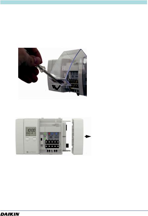
5.2Mounting of the product
Verify that the product is disconnected from mains
1.Open the cover using a screwdriver.
Fig. 5-1: Opening the cover
2. Pull off the end cover.
Fig. 5-2: Removing the end cover
RoCon UFH |
23 |

|
Mounting |
EN |
|
||
|
|
|
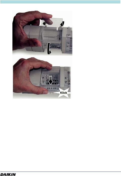
3. Connect the controller module(s) to the product and secure both with the catch.
Fig. 5-3: Connecting the base module to the controller module(s)
4. Refit the end cover onto the last controller module.
Fig. 5-4: Refitting the end cover
5. Make the electrical connections (see chapter 5.3)
RoCon UFH |
24 |
|
Mounting |
|
EN |
|
|
||
|
|
|
|
|
|
6. Refit the cover and close it. |
|
Fig. 5-5: Closing the cover
RoCon UFH |
25 |
|
Mounting |
EN |
|
||
|
|
|
5.3Electrical connection
 DANGER
ELECTRIC SHOCK
•Verify that the degree of protection against electric shock (protection class, double insulation) is not reduced by the type of electrical installation.
Failure to follow these instructions will result in death or serious injury.

 DANGER
ELECTRIC SHOCK CAUSED BY LIVE PARTS
•Disconnect the mains voltage supply before performing the work and ensure that it cannot be switched on.
•Verify that no hazards can be caused by electrically conductive objects or media.
Failure to follow these instructions will result in death or serious injury.
Verify that a connection concept has been created.
- Verify that the correct assignment of the switching channels for the timer module has been considered.
Verify that all cables are disconnected from power.
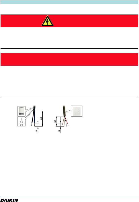
1. Strip the cables as shown.
Fig. 5-6: Stripping the cables
RoCon UFH |
26 |
|
Mounting |
EN |
|
||
|
|
|
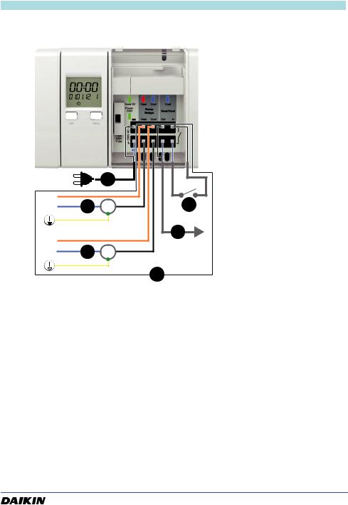
5.3.1Connection diagram
A
L
N F P
L
N E P
D
A.230 V AC supply
B.Input heating/cooling
-open: Heating
-closed: Cooling
-internal control voltage: DC 5 V
C.Cascading output voltage-
free relay contact max. AC 250 V, 3 A max. DC 30 V, 3 A
D.Options
E.Pump cooling max. AC 250 V, 3 A
B |
F. |
Pump heating |
|
max. AC 250 V, 3 A |
C
Fig. 5-7: Connection diagram base module
RoCon UFH |
27 |
|
Mounting |
EN |
|
||
|
|
|
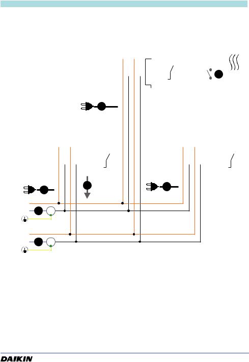
5.3.2Connection diagram in the case of multiple products
|
|
|
|
|
|
|
|
|
|
|
|
|
|
|
|
|
|
|
|
|
|
BM3 |
|
|
|
|
Pump |
Heat/Cool |
|
|
|
|
|
|
|
|
|
|
|
|
|
|
|
|
|
|
|
|
||||||||||||||||||||||
|
|
|
|
|
|
|
|
|
|
|
|
|
|
|
|
|
|
|
|
|
|
|
|
|
|
|
|
|
|
|
|
|
|
Relays |
|
|
|
|
|
|
|
|
|
|
|
|
|
|
|
|
|
|
|
|
|
|
|
|
|
|
|
|
|
|
|
|||||
|
|
|
|
|
|
|
|
|
|
|
|
|
|
|
|
|
|
|
|
|
|
|
|
|
|
|
|
|
|
|
|
Heat Cool |
Out In |
|
|
|
|
|
|
|
|
|
|
|
|
|
|
|
|
|
|
|
|
|||||||||||||||||
|
|
|
|
|
|
|
|
|
|
|
|
|
|
|
|
|
|
|
|
|
|
|
|
|
|
|
|
|
|
|
|
|
|
|
|
|
|
|
|
|
|
|
|
|
|
|
|
|
|
|
|
|
|
|
|
|
|
|
|
|
|
|
|
|
|
|
|
|
|
|
|
|
|
|
|
|
|
|
|
|
|
|
|
|
|
|
|
|
|
|
|
|
|
|
|
|
|
|
|
|
|
|
|
|
|
|
|
|
|
|
|
|
|
|
|
|
|
|
|
|
|
|
|
|
|
|
|
|
|
|
|
|
|
|
|
|
|
|
|
|
|
|
|
|
|
|
|
|
|
|
|
|
|
|
|
|
|
|
|
|
|
|
|
|
|
|
|
|
|
|
|
|
|
|
|
|
|
|
|
|
|
|
|
|
|
|
|
|
|
|
|
|
|
|
|
|
|
|
|
|
|
|
|
|
|
|
|
|
|
|
|
|
|
|
|
|
|
|
|
|
|
|
|
|
|
|
|
|
|
|
|
|
|
|
|
|
|
|
<![if ! IE]> <![endif]>230VAC |
|
|
|
|
|
|
|
|
|
|
|
|
|
|
|
|
|
|
|
|
|
|
|
|
|
|
|
|
|
|
|
|
|
|
B |
|||||||||
|
|
|
|
|
|
|
|
|
|
|
|
|
|
|
|
|
|
|
|
|
|
|
|
|
|
|
|
|
|
|
|
|
|
|
|
|
|
|
|
|
|
|
|
|
|
|
|
|
|
|
|
|
|
|
|
|
|
|
|
|||||||||||
|
|
|
|
|
|
|
|
|
|
|
|
|
|
|
|
|
|
|
|
|
|
|
|
|
|
|
|
|
|
|
|
|
|
|
|
|
|
|
|
|
|
|
|
|
|
|
|
|
|
|
|
|
|
|
|
|
|
|
|
|||||||||||
|
|
|
|
|
|
|
|
|
|
|
|
|
|
|
|
|
|
|
|
|
|
|
|
|
|
|
|
|
|
|
|
|
|
|
|
|
|
|
|
|
|
|
|
|
|
|
|
|
|
|
|
|
|
|
|
|
|
|
|
|||||||||||
|
|
|
|
|
|
|
|
|
|
|
|
|
|
|
|
|
|
|
|
|
|
|
|
|
|
|
|
|
|
|
|
|
|
|
|
|
|
|
|
|
|
|
|
|
|
|
|
|
|
|
|
|
|
|
|
|
|
|
|
|
|
|
||||||||
|
|
|
|
|
|
|
|
|
|
|
|
|
|
|
|
|
|
|
|
|
|
|
|
|
|
|
|
|
|
|
|
|
|
|
|
|
|
|
|
|
|
|
|
|
|
|
|
|
|
|
|
|
|
|
|
|
|
|
|
|
|
|
||||||||
|
|
|
|
|
|
|
|
|
|
|
|
|
|
|
|
|
|
|
|
|
|
|
|
|
|
|
|
|
|
|
|
|
|
|
|
|
|
|
|
|
|
|
|
|
|
|
|
|
|
|
|
|
|
|
|
|
|
|
|
|
|
|
|
|
|
|
|
|
|
|
|
|
|
|
|
|
|
|
|
|
|
|
|
|
|
|
|
|
|
|
|
|
|
|
|
|
|
|
|
|
|
|
|
|
|
|
|
|
|
|
|
|
|
|
|
|
|
|
|
|
|
|
|
|
|
|
|
|
|
|
|
|
|
|
|
|
|
|
|
|
|
|
|
|
|
|
|
|
|
|
|
|
|
|
|
|
|
|
|
|
|
|
|
|
|
|
|
|
|
|
|
|
|
|
|
|
|
|
|
|
|
|
|
|
|
|
|
|
|
|
|
|
|
|
|
|
|
|
|
|
|
|
|
|
|
|
|
|
|
|
|
|
|
|
|
|
|
|
|
|
|
|
|
|
|
|
|
|
|
|
|
|
|
|
A |
|
|
|
|
|
|
|
|
|
|
|
|
|
|
|
|
|
|
|
|
|
|
|
|
|
|
|
|
|
|
|
|
|
|
|
|
|
|
|
|
|
|||||||
|
|
|
|
|
|
|
|
|
|
|
|
|
|
|
|
|
|
|
|
|
|
|
|
|
|
|
|
|
|
|
|
|
|
|
|
|
|
|
|
|
|
|
|
|
|
|
|
|
|
|
|
|
|
|
|
|
|
|
|
|
|
|
||||||||
|
|
|
|
|
|
|
|
|
|
|
|
|
|
|
|
|
|
|
|
|
|
|
|
|
|
|
|
|
|
|
|
|
|
|
|
|
|
|
|
|
|
|
|
|
|
|
|
|
|
|
|
|
|
|
|
|
|
|
|
|
|
|
||||||||
|
|
|
|
|
|
|
|
|
|
|
|
|
|
|
|
|
|
|
|
|
|
|
|
|
|
|
|
|
|
|
|
|
|
|
|
|
|
|
|
|
|
|
|
|
|
|
|
|
|
|
|
|
|
|
|
|
|
|
|
|
|
|
||||||||
|
|
|
|
|
|
|
|
|
|
|
|
|
|
|
|
|
|
|
|
|
|
|
|
|
|
|
|
|
|
|
|
|
|
|
|
|
|
|
|
|
|
|
|
|
|
|
|
|
|
|
|
|
|
|
|
|
|
|
|
|
|
|
|
|
|
|||||
|
|
|
|
|
|
|
|
|
|
|
|
|
|
|
|
|
|
|
|
|
|
|
|
|
|
|
|
|
|
|
|
|
|
|
|
|
|
|
|
|
|
|
|
|
|
|
|
|
|
|
|
|
|
|
|
|
|
|
|
|
|
|
|
|||||||
BM1 |
|
|
|
|
|
|
Pump |
Heat/Cool |
|
|
|
|
|
|
|
|
|
|
BM2 |
|
|
|
|
|
Pump |
Heat/Cool |
|
|||||||||||||||||||||||||||||||||||||||||||
|
|
|
|
|
|
|
|
|
|
Relays |
|
|
|
|
|
|
|
|
|
|
|
|
|
|
|
|
|
|
|
|
|
|
|
|
|
|
|
|
|
|
|
|
|
|
|
|
|
|
|
|
Relays |
|
|
|
|
|
|
|
|
|
|
|||||||||
|
|
|
|
|
|
|
|
Heat Cool |
Out In |
|
|
|
|
|
|
|
|
|
|
|
|
|
|
|
|
|
|
|
|
|
|
|
Heat Cool |
Out In |
|
|||||||||||||||||||||||||||||||||||
|
|
|
|
|
|
|
|
|
|
|
|
|
|
|
|
|
|
|
|
|
|
|
|
|
|
|
|
|
|
|
|
|
|
|
|
|
|
|
|
|
|
|
|
|
|
|
|
|
|
|
|
|
|
|
|
|
|
|
|
|
|
|
|
|
|
|
|
|
|
|
|
|
|
|
|
|
|
|
|
|
|
|
|
|
|
|
|
|
|
|
|
|
|
|
|
|
|
|
|
|
|
|
|
|
|
|
|
|
|
|
|
|
|
|
|
|
|
|
|
|
|
|
|
|
|
|
|
|
|
|
|
|
|
|
|
|
|
|
|
|
|
|
|
|
|
|
|
|
|
|
|
|
|
|
|
|
|
|
|
|
|
|
|
|
|
|
|
|
|
|
|
|
|
|
|
|
|
|
|
|
|
|
|
|
|
|
|
|
|
|
|
|
|
|
|
|
|
|
|
|
|
|
|
|
|
|
|
|
|
|
|
|
|
<![if ! IE]> <![endif]>230VAC |
|
|
|
|
|
|
|
|
|
|
|
|
|
|
|
|
|
|
|
|
|
|
|
|
|
|
|
|
|
|
|
|
|
|
|
|
|
|
|
|
|
|
<![if ! IE]> <![endif]>230VAC |
|
|
|
|
|
|
|
|
|
|
|
|
|
|
|
|
|
|
|
|
|
|
||||
|
|
|
|
|
|
|
|
|
|
|
|
|
|
|
|
|
|
|
|
|
|
|
|
|
|
|
|
|
|
|
|
|
|
|
|
|
|
|
|
|
|
|
|
|
|
|
|
|
|
|
|
|
|
|
|
|
|
|||||||||||||
|
|
|
|
|
|
|
|
|
|
|
|
|
|
|
|
|
|
|
|
|
|
|
|
|
|
|
|
|
|
|
|
|
|
|
|
|
|
|
|
|
|
|
|
|
|
|
|
|
|
|
|
|
|
|
|
|
|
|||||||||||||
|
|
|
|
|
|
|
|
|
|
|
|
|
|
|
|
|
|
|
|
|
|
|
|
|
|
|
|
|
|
|
|
|
|
|
|
|
|
|
|
|
|
|
|
|
|
|
|
|
|
|
|
|
|
|
|
|
|
|||||||||||||
|
|
|
|
|
|
|
|
|
|
|
|
|
|
|
|
|
|
|
|
|
|
|
|
|
|
|
|
|
|
|
|
|
|
|
|
|
|
|
|
|
|
|
|
|
|
|
|
|
|
|
|
|
|
|
|
|
|
|
|
|
|
|
|
|
|
|
|
|
|
|
|
|
|
|
|
|
|
|
|
|
|
|
|
|
|
|
|
|
|
|
|
|
|
|
|
|
|
|
|
|
|
|
|
|
|
|
|
|
|
|
|
|
|
|
|
|
|
|
|
|
|
|
|
|
|
|
|
|
|
|
|
|
|
|
|
|
|
|
|
|
|
|
|
|
|
|
|
|
|
|
|
|
|
|
|
|
|
|
|
|
|
|
|
|
|
|
|
|
|
|
|
|
|
|
|
|
|
|
|
|
|
|
|
|
|
|
|
|
|
|
|
|
|
|
|
|
|
|
|
|
|
|
|
|
|
|
|
|
|
|
|
|
|
|
|
|
|
|
|
|
|
|
|
|
|
|
|
|
|
|
|
|
|
|
|
|
|
|
|
|
|
|
|
|
|
|
|
|
|
|
|
|
|
|
|
|
|
|
|
|
|
|
|
|
|
|
|
|
|
|
|
|
|
|
|
|
|
|
|
|
|
|
|
|
|
|
|
|
|
|
|
|
|
|
|
|
|
|
|
|
|
|
|
|
|
|
|
|
|
|
|
|
|
|
|
|
|
|
|
|
|
|
|
|
|
|
|
|
|
|
|
|
|
|
|
|
|
|
|
|
|
|
|
|
|
|
|
|
|
|
|
|
|
|
|
A |
|
|
|
|
|
|
|
|
|
|
|
|
C |
|
|
|
|
|
|
|
|
|
|
|
|
|
|
|
|
|
A |
|
|
|
|
|
|
|
|
|
|
|
|
|
|
|
|
|
|
|
|
|
|||||||||||||||||
|
|
|
|
|
|
|
|
|
|
|
|
|
|
|
|
|
|
|
|
|
|
|
|
|
|
|
|
|
|
|
|
|
|
|
|
|
|
|
|
|
|
|
|
|
|
|
|
|
|
|||||||||||||||||||||
|
|
|
|
|
|
|
|
|
|
|
|
|
|
|
|
|
|
|
|
|
|
|
|
|
|
|
|
|
|
|
|
|
|
|
|
|
|
|
|
|
|
|
|
|
|
|
|
|
|
|
|
|
|
|
|
|
|
|
|
|
|
|
|
|
|
|
|
|||
|
|
|
|
|
|
|
|
|
|
|
|
|
|
|
|
|
|
|
|
|
|
|
|
|
|
|
|
|
|
|
|
|
|
|
|
|
|
|
|
|
|
|
|
|
|
|
|
|
|
|
|
|
|
|
|
|
|
|
|
|
|
|
|
|
|
|
|
|
|
|
L
N F P
L
N E P
A. |
Upper floor |
D. |
Heating |
B. |
Ground floor |
E. |
Pump cooling |
C. Basement |
max. AC 250 V, 3 A |
|
F. Pump heating |
||
|
||
|
max. AC 250 V, 3 A |
|
Fig. 5-8: Connection diagram for cascading example |
||
RoCon UFH |
28 |
 Loading...