


REYQ192XAYDU
Table of contents
 Loading...
Dakin REYQ192XAYDU, REYQ96XAYCU, REYQ96XATJU, REYQ72XAYCU, REYQ72XATJU User Manual
...
English
Français
Español
INSTALLATION MANUAL
MODEL
REYQ72XATJU
REYQ96XATJU
REYQ120XATJU
REYQ144XATJU
REYQ168XATJU
REYQ192XATJU
REYQ216XATJU
REYQ240XATJU
REYQ264XATJU
REYQ288XATJU
REYQ312XATJU
REYQ336XATJU
REYQ360XATJU
REYQ384XATJU
REYQ408XATJU
REYQ432XATJU
REYQ456XATJU
REYQ72XAYDU
REYQ96XAYDU
REYQ120XAYDU
REYQ144XAYDU
REYQ168XAYDU
REYQ192XAYDU
REYQ216XAYDU
REYQ240XAYDU
REYQ264XAYDU
REYQ288XAYDU
REYQ312XAYDU
REYQ336XAYDU
REYQ360XAYDU
REYQ384XAYDU
REYQ408XAYDU
REYQ432XAYDU
REYQ456XAYDU
REYQ72XAYCU
REYQ96XAYCU
REYQ120XAYCU
REYQ144XAYCU
REYQ168XAYCU
REYQ192XAYCU
REYQ216XAYCU
REYQ240XAYCU
REYQ264XAYCU
REYQ288XAYCU
REYQ312XAYCU
REYQ336XAYCU
REYQ360XAYCU
REYQ384XAYCU
REYQ408XAYCU
REYQ432XAYCU
VRV System air conditioner
Please visit http://www.daikinac.com/content/resources/manuals for the most current version of installation
instructions. In the event of conicting information, the online installation instruction is to be used.
Veuillez visiter http://www.daikinac.com/content/resources/manuals pour obtenir la version la plus récente des
instructions d’installation. En cas de conit d’informations, les instructions d’installation en ligne doivent être
utilisées.
Visite http://www.daikinac.com/content/resources/manuals para obtener la versión más actualizada de las
instrucciones de instalación. En caso de información conictiva, se debe utilizar la instrucción de instalación en
línea.
3P477778-7G
3P477778-7G Englishi
Safety considerations
Read these Safety considerations for Installation carefully be-
fore installing an air conditioner or heat pump. After complet-
ing the installation, make sure that the unit operates properly
during the startup operation.
Instruct the customer on how to operate and maintain the
unit.
Inform customers that they should store this Installation
Manual with the Operation Manual for future reference.
Always use a licensed installer or contractor to install this
product.
Improper installation can result in water or refrigerant leak-
age, electrical shock, re, or explosion.
Meanings of DANGER, WARNING, CAUTION, and NOTE
Symbols:
DANGER ........ Indicates an imminently hazardous
situation which, if not avoided, will
result in death or serious injury.
WARNING ....... Indicates a potentially hazardous
situation which, if not avoided,
could result in death or serious
injury.
CAUTION ........ Indicates a potentially hazardous
situation which, if not avoided,
may result in minor or moderate
injury. It may also be used to alert
against unsafe practices.
NOTE ........... Indicates situations that may result
in equipment or property-damage
accidents only.
INFORMATION ... This symbol identies useful tips
or additional information.
DANGER
• Refrigerant gas is heavier than air and replaces oxygen. A
massive leak will result in oxygen depletion, especially in
basements, and an asphyxiation hazard will result in seri-
ous injury or death.
• Do not ground units to water pipes, gas pipes, telephone
wires, or lightning rods as incomplete grounding will result
a severe shock hazard resulting in severe injury or death.
Additionally, grounding to gas pipes will result a gas leak
and potential explosion resulting in severe injury or death.
• If refrigerant gas leaks during installation, ventilate the
area immediately. Refrigerant gas will result in producing
toxic gas if it comes into contact with re. Exposure to this
gas will result in severe injury or death.
• After completing the installation work, check that the re-
frigerant gas does not leak throughout the system.
• Do not install unit in an area where ammable materials
are present due to risk of explosions that will result in seri-
ous injury or death.
• Safely dispose all packing and transportation materials
in accordance with federal/state/local laws or ordinances.
Packing materials such as nails and other metal or wood
parts, including plastic packing materials used for trans-
portation will result in injuries or death by suffocation.
WARNING
• Only qualied personnel must carry out the installation
work. Installation must be done in accordance with this
installation manual. Improper installation could result in
water leakage, electric shock, or re.
• When installing the unit in a small room, take measures to
keep the refrigerant concentration from exceeding allow-
able safety limits. Excessive refrigerant leaks, in the event
of an accident in a closed ambient space, could result in
oxygen deciency.
• Use only specied accessories and parts for installation
work. Failure to use specied parts could result in water
leakage, electric shocks, re, or the unit falling.
• Install the air conditioner or heat pump on a foundation
strong enough that it can withstand the weight of the unit.
A foundation of insufcient strength could result in the unit
falling and causing injuries.
• Take into account strong winds, typhoons, or earthquakes
when installing. Improper installation could result in the
unit falling and causing accidents.
• Make sure that a separate power supply circuit is pro-
vided for this unit and that all electrical work is carried
out by qualied personnel according to local, state and
national regulations. An insufcient power supply capacity
or improper electrical construction could result in electric
shocks or re.
• Make sure that all wiring is secured, that specied wires
are used, and that no external forces act on the terminal
connections or wires. Improper connections or installation
could result in re.
• When wiring, position the wires so that the control box
cover can be securely fastened. Improper positioning of
the control box cover could result in electric shocks, re, or
the terminals overheating.
• Before touching electrical parts, turn off the unit.
• This equipment can be installed with a Ground-Fault Cir-
cuit Interrupter (GFCI). Although this is a recognized mea-
sure for additional protection, with the grounding system in
North America, a dedicated GFCI is not necessary.
• Securely fasten the unit terminal cover (panel). If the
terminal cover/panel is not installed properly, dust or
water may enter the outdoor unit and could result in re or
electric shock.
• When installing or relocating the system, keep the refriger-
ant circuit free from substances other than the specied
refrigerant (R410A) such as air. Any presence of air or oth-
er foreign substance in the refrigerant circuit could result
in abnormal pressure rise or rupture, resulting in injury.
• Do not change the setting of the protection devices. If the
pressure switch, thermal switch, or other protection device
is shorted and operated forcibly, or parts other than those
specied by Daikin are used, re or explosion could result.
3P477778-7G English ii
CAUTION
• Do not touch the switch with wet ngers. Touching a switch
with wet ngers may result in electric shock.
• Do not allow children to play on or around the unit or it
may result in injury.
• The heat exchanger ns are sharp enough to cut, and
may result in injury if improperly used. To avoid injury wear
glove or cover the ns when working around them.
• Do not touch the refrigerant pipes during and immediately
after operation as the refrigerant pipes may be hot or
cold, depending on the condition of the refrigerant ow-
ing through the refrigerant piping, compressor, and other
refrigerant cycle parts. It may result in your hands get-
ting burns or frostbite if you touch the refrigerant pipes.
To avoid injury, give the pipes time to return to normal
temperature or, if you must touch them, be sure to wear
proper gloves.
• Install drain piping to proper drainage. Improper drain pip-
ing may result in water leakage and property damage.
• Insulate piping to prevent condensation.
• Be careful when transporting the product.
• Do not turn off the power immediately after stopping
operation. Always wait for at least 5 minutes before turning
off the power. Otherwise, water leakage may result.
• Do not use a charging cylinder. Using a charging cylinder
may cause the refrigerant to deteriorate.
• Refrigerant R410A in the system must be kept clean, dry,
and tight.
(a) Clean and Dry - Foreign materials (including mineral
oils such as SUNISO oil or moisture) should be pre-
vented from getting into the system.
(b) Tight - R410A does not contain any chlorine, does
not destroy the ozone layer, and does not reduce the
earth’s protection again harmful ultraviolet radiation.
R410A can contribute to the greenhouse effect if it is
released. Therefore take proper measures to check
for the tightness of the refrigerant piping installation.
Read the chapter Refrigerant Piping and follow the
procedures.
• Since R410A is a blend, the required additional refriger-
ant must be charged in its liquid state. If the refrigerant is
charged in a state of gas, its composition can change and
the system will not work properly.
• The indoor unit is for R410A. See the catalog for indoor
models that can be connected. Normal operation is not
possible when connected to other units.
• Remote controller (wireless kit) transmitting distance can
be shorter than expected in rooms with electronic uores-
cent lamps (inverter or rapid start types). Install the indoor
unit far away from uorescent lamps as much as possible.
• Indoor units are for indoor installation only. Outdoor units
can be installed either outdoors or indoors. This unit is for
indoor use.
• Do not install the air conditioner or heat pump in the fol-
lowing locations:
(a) Where a mineral oil mist or oil spray or vapor is pro-
duced, for example, in a kitchen.
Plastic parts may deteriorate and fall off and thus may
result in water leakage.
(b) Where corrosive gas, such as sulfurous acid gas, is
produced.
Corroding copper pipes or soldered parts may result
in refrigerant leakage.
(c) Near machinery emitting electromagnetic waves.
Electromagnetic waves may disturb the operation of
the control system and cause the unit to malfunction.
(d) Where ammable gas may leak, where there is car-
bon ber, or ignitable dust suspension in the air, or
where volatile ammables such as thinner or gasoline
are handled. Operating the unit in such conditions
may result in a re.
• Take adequate measures to prevent the outdoor unit from
being used as a shelter by small animals. Small animals
making contact with electrical parts may result in malfunc-
tions, smoke, or re. Instruct the customer to keep the
area around the unit clean.
NOTE
• Install the power supply and transmission wires for the in-
door and outdoor units at least 3.5ft.(1m) away from tele-
visions or radios to prevent image interference or noise.
Depending on the radio waves, a distance of 3.5ft.(1m)
may not be sufcient to eliminate the noise.
• Dismantling the unit, treatment of the refrigerant, oil and
additional parts must be done in accordance with the
relevant local, state, and national regulations.
• Do not use the following tools that are used with con-
ventional refrigerants: gauge manifold, charge hose, gas
leak detector, reverse ow check valve, refrigerant charge
base, vacuum gauge, or refrigerant recovery equipment.
• If the conventional refrigerant and refrigerator oil are
mixed in R410A, the refrigerant result in deterioration.
• This air conditioner or heat pump is an appliance that
should not be accessible to the general public.
• As design pressure is 478 psi (3.3 MPa), the wall thick-
ness of eld-installed pipes should be selected in accor-
dance with the relevant local, state, and national regula-
tions.
Codes and Regulations
This product is designed and manufactured to comply with
national codes. Installation in accordance with such codes
and/or prevailing local codes/regulations is the responsibility
of the installer. The manufacturer assumes no responsibility
for equipment installed in violation of any codes or regula-
tions. Rated performance is achieved after 72 hours of opera-
tion.
Make sure to use a DAIKIN specied checker while measur-
ing sub cooling. Do not use the check valve or the other port
to measure it.

1 3P477778-7G English
REYQ72XATJU
REYQ96XATJU
REYQ120XATJU
REYQ144XATJU
REYQ168XATJU
REYQ192XATJU
REYQ216XATJU
REYQ240XATJU
REYQ264XATJU
REYQ288XATJU
REYQ312XATJU
REYQ336XATJU
REYQ360XATJU
REYQ384XATJU
REYQ408XATJU
REYQ432XATJU
REYQ456XATJU
REYQ72XAYDU
REYQ96XAYDU
REYQ120XAYDU
REYQ144XAYDU
REYQ168XAYDU
REYQ192XAYDU
REYQ216XAYDU
REYQ240XAYDU
REYQ264XAYDU
REYQ288XAYDU
REYQ312XAYDU
REYQ336XAYDU
REYQ360XAYDU
REYQ384XAYDU
REYQ408XAYDU
REYQ432XAYDU
REYQ456XAYDU
REYQ72XAYCU
REYQ96XAYCU
REYQ120XAYCU
REYQ144XAYCU
REYQ168XAYCU
REYQ192XAYCU
REYQ216XAYCU
REYQ240XAYCU
REYQ264XAYCU
REYQ288XAYCU
REYQ312XAYCU
REYQ336XAYCU
REYQ360XAYCU
REYQ384XAYCU
REYQ408XAYCU
REYQ432XAYCU
VRV System air conditioner
Installation Manual
CONTENTS
Safety considerations .....................................i
Codes and Regulations .................................. ii
1. Introduction ...........................................2
1.1. General information ................................. 2
1.2. Combinations and options ....................... 2
1.3. Indoor capacity range .............................. 3
1.4. Scope of the manual ............................... 3
2. Accessories ...........................................3
2.1. Accessories supplied with this unit .......... 3
3. Overview of unit ....................................4
3.1. Opening the unit ...................................... 4
3.2. Technical and Electrical specications .... 4
3.3. Main components .................................... 4
4. Selecting an installation location ........4
4.1. General precautions on installation ......... 4
4.2. Weather related precautions ................... 5
4.3. Selecting a location in cold climates ....... 5
5. Dimensions and service space ............ 6
5.1. Dimensions of outdoor unit ..................... 6
5.2. Service space.......................................... 6
6. Inspecting, handling and unpacking
the unit ...................................................7
6.1. Inspection ................................................ 7
6.2. Handling .................................................. 7
6.3. Unpacking ............................................... 7
6.4. Installing the unit ..................................... 8
6.5. Method for removing shipping plates ...... 8
6.6. Method for opening the sliding plate ....... 9
7. Refrigerant pipe size and allowable pipe
length .............................................................9
7.1. General information ................................. 9
7.2. Selection of piping material ..................... 9
7.3. Selection of piping size ........................... 9
7.4. Selection of refrigerant branch kits ........ 10
7.5. System piping (length) limitations ......... 11
8. Precautions on refrigerant piping ......14
8.1. Caution for brazing ................................ 14
8.2. Connecting the refrigerant piping .......... 14
8.3. Guidelines for handling stop valve......... 17
9. Field wiring ..........................................18
9.1. Power circuit, safety device and cable
requirements ......................................... 19
9.2. Wiring connection example for whole
system ................................................... 19
9.3. Leading wire procedure ......................... 19
9.4. Transmission wiring connection
procedure .............................................. 20
9.5. Power wiring connection procedure ...... 21
9.6. Procedure for Wiring Inside Units .......... 21
10. Air tight test and vacuum drying .......22
11. Pipe insulation ..................................... 23
12. Checking of device and installation
conditions ............................................24
13. Makingeldsettings ........................... 24
13.1. Accessing the push buttons on the
printed circuit board ............................... 24
13.2. Operating the push buttons and DIP
switches on the printed circuit board ..... 24
13.3. Connecting the PC congurator to the
outdoor unit ........................................... 26
14. Charging refrigerant ............................ 26
14.1. Precautions ........................................... 26
14.2. Calculating the additional refrigerant
charge ................................................... 26
14.3. Method for adding refrigerant ................ 28
15. Start-upandconguration .................30
15.1. Checks before initial start up ................. 30
15.2. Monitoring function and eld settings .... 31
15.3.
Energy saving and optimum operation
... 37
15.4. Test operation ........................................ 39
15.5. Malfunction code list .............................. 40
16. Operation of the unit ........................... 43
17. Maintenance and service .................... 43
17.1. Maintenance introduction ...................... 43
17.2. Service precautions............................... 43
17.3. Service mode operation ........................ 45
18. Caution for refrigerant leaks ..............45
18.1. Introduction ........................................... 45
19. Disposal requirements ........................45
The original instructions are written in English. All other
languages are translations of the original instructions.
23P477778-7G English
1. Introduction
1.1. General information
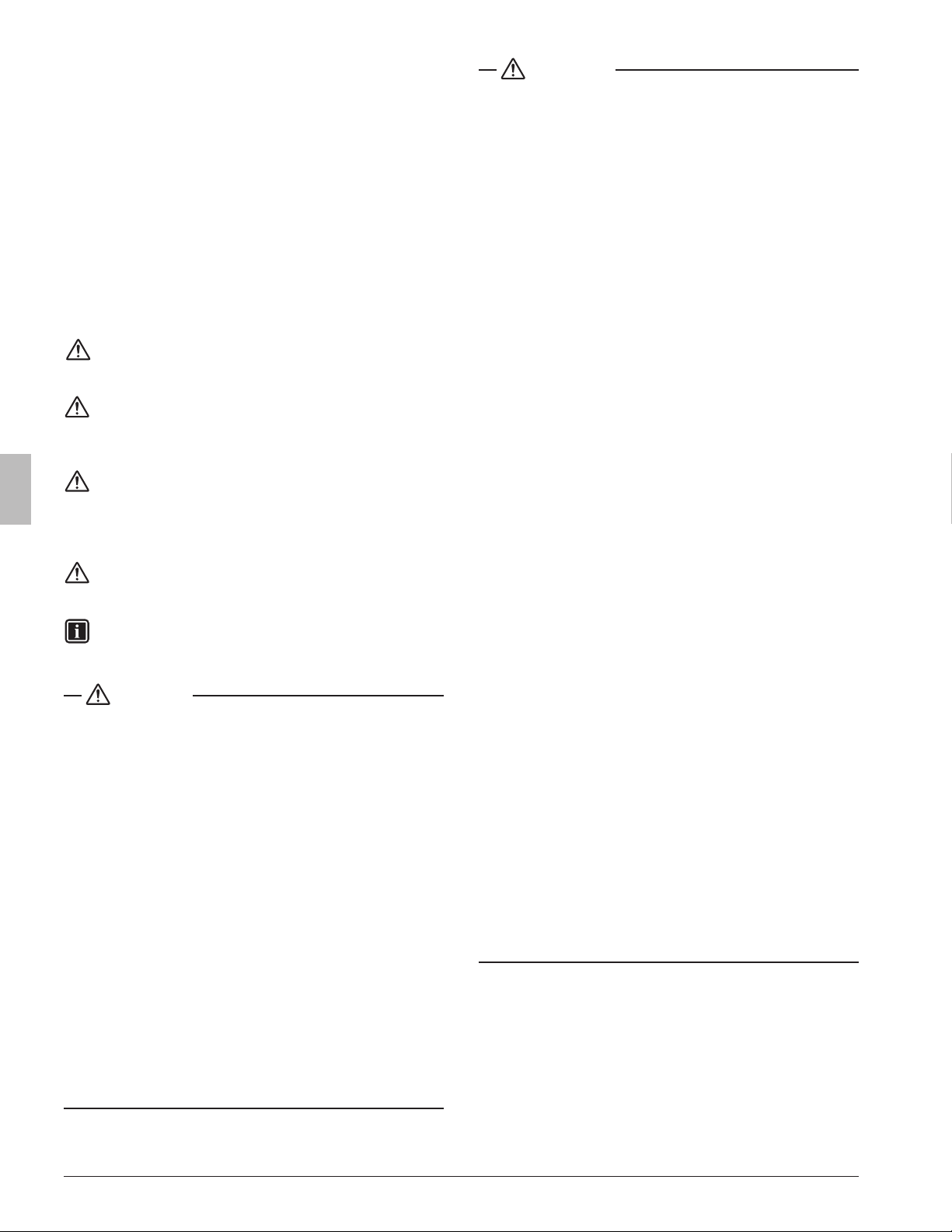
This installation manual concerns the VRV REYQ-X series, full
inverter driven, heat pump system.
6
7
3
5
4
2
1
5
4
6
3
1 Outdoor unit
2 Refrigerant piping
3 Branch Selector unit
4 VRV indoor unit
5 Cool/Heat selector (single Branch Selector unit only)
6 User interface (dedicated depending on indoor unit type)
7
User interface (wireless, dedicated depending on indoor unit type)
INFORMATION
Not all combinations of indoor units are allowed. For guidance, see
1.2. Combinations and options.
1.2 . Combinations and options
The VRV REYQ-X series heat recovery system can be combined with
several types of indoor units and is intended for R410A use only.
For an overview which units are available you can consult the product
catalogue for VRV REYQ-X series.
NOTE
To be sure your system setup (outdoor unit + Branch Selector unit(s)
+ indoor unit(s)) will work, you have to consult the latest technical
engineering data for VRV REYQ-X series.
An overview is given indicating the allowed combinations of indoor
units and outdoor units. Not all combinations are allowed. They are
subject to rules (combination between outdoor-indoor, single outdoor
unit use, multiple outdoor units use, combinations between indoor
units, etc.) mentioned in the technical engineering data.
The Branch Selector units that combined with REYQ-X units for
changing the refrigerant ow to indoor units are T type
(BSQ-TVJ, BS-Q54TVJ) only. Do not combine the T type and P type
(BSVQ-PVJU, BSV-Q36PVJU) in the system. Combination of T type
and P type cause malfunction.
1.2 .1. Indoor units combinations
In general VRV indoor units can be connected to REYQ-X units.
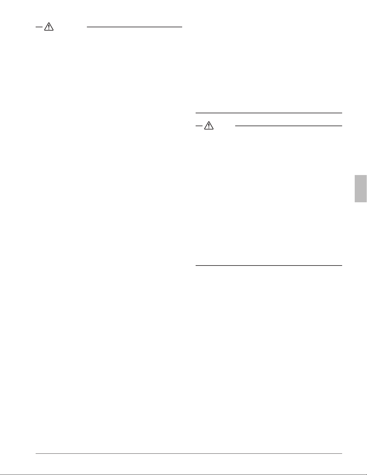
1.2.2. Outdoor units combinations
Combination for REYQ-X units are as indicated in tables right, where
REYQ 144-456 consists of multiple REYQ 96-120 single modules as
indicated.
72 96 120 144 168
REYQ72XATJU/XAYDU/XAYCU 1
REYQ96XATJU/XAYDU/XAYCU 1
REYQ120XATJU/XAYDU/XAYCU 1
REYQ144XATJU/XAYDU/XAYCU 1
REYQ168XATJU/XAYDU/XAYCU 1
REYQ192XATJU/XAYDU/XAYCU 2
REYQ216XATJU/XAYDU/XAYCU 1 1
REYQ240XATJU/XAYDU/XAYCU 2
REYQ264XATJU/XAYDU/XAYCU 1 1
REYQ288XATJU/XAYDU/XAYCU 2
REYQ312XATJU/XAYDU/XAYCU 1 1
REYQ336XATJU/XAYDU/XAYCU 2
REYQ360XATJU/XAYDU/XAYCU 3
REYQ384XATJU/XAYDU/XAYCU 2 1
REYQ408XATJU/XAYDU/XAYCU 1 2
REYQ432XATJU/XAYDU/XAYCU 3
REYQ456XATJU/XAYDU 2 1
To install the outdoor unit, the following accessory parts are also
required.
1 Refrigerant branch kit.
Description
Model name
(for 3 pipes) (for 2 pipes)
REFNET header
KHRP25M33H9
KHRP25M33HA
KHRP26M22H9
KHRP26M22HA
KHRP25M72H9
KHRP25M72HA
KHRP26M33H9
KHRP26M33HA
KHRP25M73HU9
KHRP25M73HUA
KHRP26M72H9
KHRP26M72HA
REFNET joint
KHRP25A22T9
KHRP25A22TA
KHRP26A22T9
KHRP26A22TA
KHRP25A33T9
KHRP25A33TA
KHRP26A33T9
KHRP26A33TA
KHRP25M72TU9
KHRP25M72TUA
KHRP26M72TU9
KHRP26M72TUA
KHRP25M73TU9
KHRP25M73TUA
–
For the selection of the optimal branch kit, refer to 7.4. Selection of
refrigerant branch kits on page10.
2 Outdoor unit multi connection piping kit.
Number of outdoor units connected
2 3
BHFP26P100U
BHFP26P100UA
BHFP26P151U
BHFP26P151UA
3 In order to control the cooling or heating operation from a central
location, the following option can be connected:
- Cool/Heat selector: KRC19-26A
- With optional xing box for the switch: KJB111A
- Centralized control devices (e.g., intelligent Touch Manager)
4 To instruct specic operation with an external input coming from a
central control the external control adaptor (DTA104A61/62) can
be used. Instructions (group or individual) can be instructed for low
noise operation and power consumption limitation operation.
5 For REYQ-X units it is also possible to make several commissioning
eld settings through a personal computer interface. For this option
999482P3 is required which is a dedicated cable to communicate
with the outdoor unit. The software for the user interface program
can be obtained from your local Daikin sales ofce.
INFORMATION
Refer to the technical engineering data for the latest option names.
3 3P477778-7G English
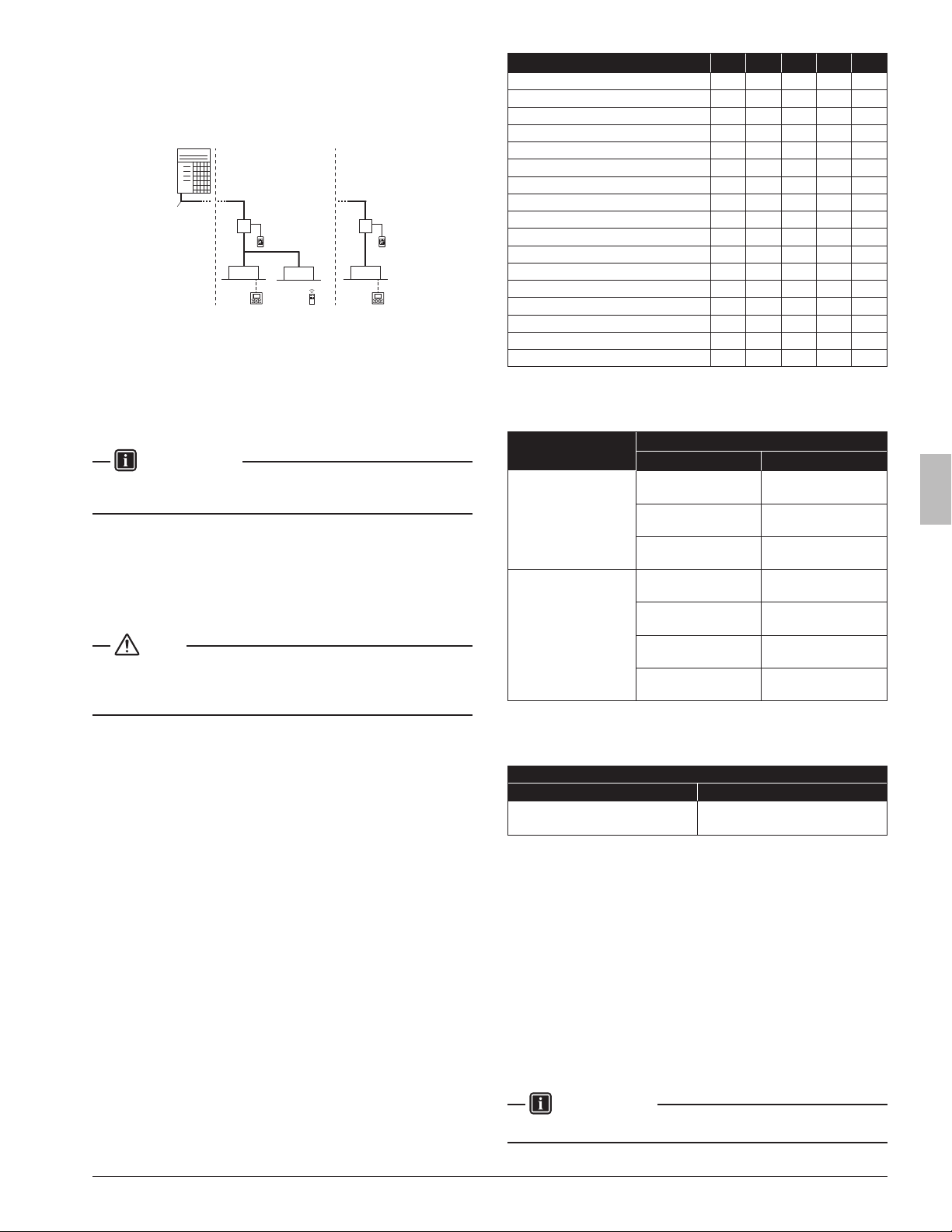
1.3. Indoor capacity range
1.3.1. Connection Ratio
Connection Ratio = Total capacity index of the indoor units / Capac-
ity index of the outdoor units
Type
Min. connection ratio
Types of connected outdoor units
REYQ-X type
Single outdoor units
50% (*1)Double outdoor units
Triple outdoor units
*1. 70% : REYQ72X type
Type
Max. connection ratio
Types of connected indoor units
Types of connected air treatment
When using
only FXDQ,
FXMQ-PB,
FXAQ,
FXSQ07-54 TA
When using
at least one
FXZQ05 TA,
FXSQ05 TA,
FXFQ07/09
When using
other indoor
unit models
FXMQ-MF
When
FXMQ-MF
is only
connected
When
FXMQ-MF and
indoor units are
connected
Single out-
door unit
200% *1
180% *1 200% *1
100% 100% *2
Double
outdoor
units
160% *1 160% *1
Triple out-
door units
130% *1 130% *1
Notes: *1. If the operational capacity of indoor units is more than
130%, low airow operation is enforced in all the indoor
units.
*2. When outdoor-air processing units (FXMQ-MF) and
standard indoor units are connected, the total connection
capacity of the outdoor-air processing units (FXMQ-MF)
must not exceed 30% of the capacity index of the outdoor
units. And the connection ratio must not exceed 100%.
1.3.2. Outdoor Unit Combinations
Total capacity of indoor units needs to be within the specied range.
REYQ-X type
<Outdoor unit>
<Total capacity index of indoor units>
REYQ72XATJU/XAYDU/XAYCU . . . . . . . . . . . . 51-93
REYQ96XATJU/XAYDU/XAYCU . . . . . . . . . . . . 48-124
REYQ120XATJU/XAYDU/XAYCU . . . . . . . . . . . . 60-156
REYQ144XATJU/XAYDU/XAYCU . . . . . . . . . . . . 72-187
REYQ168XATJU/XAYDU/XAYCU . . . . . . . . . . . . 82-218
REYQ192XATJU/XAYDU/XAYCU . . . . . . . . . . . . 96-249
REYQ216XATJU/XAYDU/XAYCU . . . . . . . . . . . . 108-280
REYQ240XATJU/XAYDU/XAYCU . . . . . . . . . . . . 120-312
REYQ264XATJU/XAYDU/XAYCU . . . . . . . . . . . . 132-343
REYQ288XATJU/XAYDU/XAYCU . . . . . . . . . . . . 144-374
REYQ312XATJU/XAYDU/XAYCU . . . . . . . . . . . . 156-405
REYQ336XATJU/XAYDU/XAYCU . . . . . . . . . . . . 168-436
REYQ360XATJU/XAYDU/XAYCU . . . . . . . . . . . . 180-468
REYQ384XATJU/XAYDU/XAYCU . . . . . . . . . . . . 192-499
REYQ408XATJU/XAYDU/XAYCU . . . . . . . . . . . . 204-530
REYQ432XATJU/XAYDU/XAYCU . . . . . . . . . . . . 216-561
REYQ456XATJU/XAYDU . . . . . . . . . . . . 228-592
NOTE
Higher capacity than the above table can be selected, this may affect
heating and cooling capacity. For additional information see technical
engineering data.
1.4. Scope of the manual
This manual describes the procedures for handling, installing and
connecting the VRV REYQ-X series outdoor units. This manual has
been prepared to ensure adequate maintenance of the unit, and it will
provide help in case problems occur.
INFORMATION
The installation of the indoor unit(s) is described in the indoor unit
installation manual provided with the indoor unit(s).
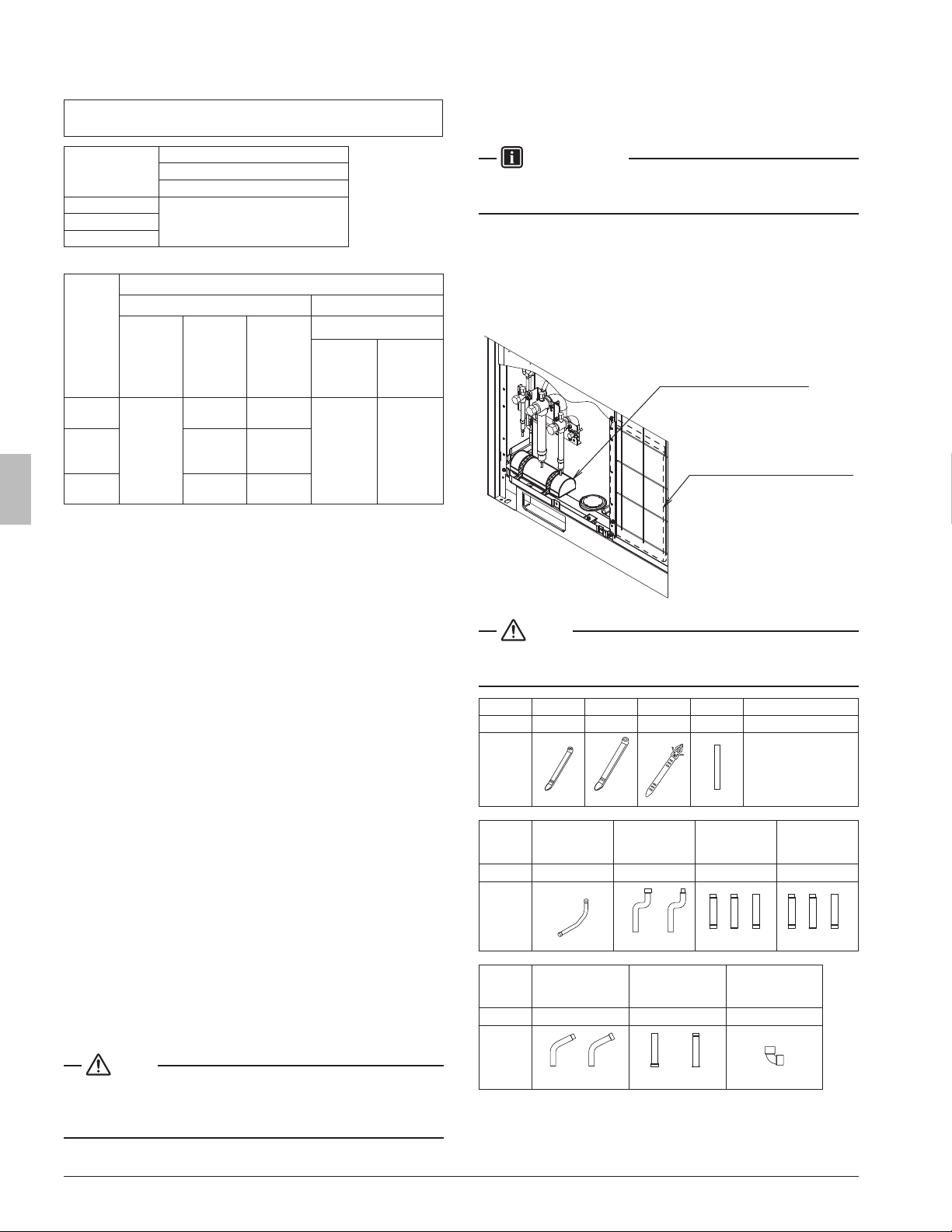
2. Accessories
2.1. Accessories supplied with this unit
Conrm the following accessories are included. The storage location
of the accessories is shown in the gure below.
Accessories assy (piping)
Accessories assy (operation
and installation manual)
NOTE
Do not throw away any of the accessories until installation is complete.
They are needed for installation work.
Name Clamp (1) Clamp (2) Clamp (3) Vinyl tube Manuals, etc.
Quantity 7 pcs. 1 pc. 1 pc. 5 pcs. 1 pc. each
Shape
(Small)
(Large)
• Operation Manual
•
Installation Manual
•
REQUEST FOR THE
INDICATION label
(Installation records)
Name
Liquid side
accessory
pipe (1)
Liquid side
accessory
pipe (2)
Gas side
accessory
pipe (1)
Gas side
accessory
pipe (2)
Quantity 1 pc. 1 pc. 1 pc. 1 pc.
Shape
168X72-144X
72,120X 144,168X96X
96,144,168X
120X72X
Name
High and low gas
side accessory
pipe (1)
High and low gas
side accessory
pipe (2)
L type
accessory joint
Quantity 1 pc. 1 pc. 2 pcs.
Shape
96-168X72X
72,96X 120-168X
43P477778-7G English
3. Overview of unit
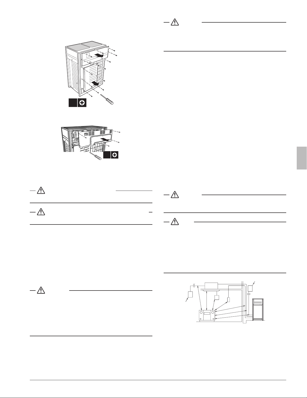
3.1. Opening the unit
To gain access to the unit, front panels need to be opened as follows:
14x
Once the front panel open, the control box can be accessed by remov-
ing the control box cover as follows.
6x
For service purposes, the push buttons on the main printed circuit
board need to be accessed. To access these push buttons, the control
box cover does not need to be opened. See 13. Making eld settings
on page24.
DANGER: ELECTRICAL SHOCK
See Safety considerations on pagei.
DANGER: DO NOT TOUCH PIPING AND INTERNAL PARTS
See Safety considerations on pagei.
3.2. TechnicalandElectricalspecications
Refer to the Engineering Data Book for the complete list of specica-
tions.
3.3. Main components
For main components and function of the main components, refer to
the Engineering Data Book.
4. Selecting an installation location
WARNING
Be sure to provide for adequate measures in order to prevent that the
unit is used as a shelter by small animals.
Small animals making contact with electrical parts can cause malfunc-
tions, smoke or re. Please instruct the customer to keep the area
around the unit clean and clear.
In a domestic environment this product may cause radio interference
in which case the user may be required to take adequate measures.
CAUTION
Appliance not accessible to the general public, install it in a secured
area, protected from easy access.
This unit, both indoor and outdoor, is suitable for installation in a com-
mercial and light industrial environment.
4.1. General precautions on installation
Select an installation site that meets the following requirements:
•
The foundation must be strong enough to support the weight of the unit.
• Installation location is at to prevent vibrations and noise generation
and to have sufcient stability.
• The space around the unit is adequate for maintenance and servic-
ing (refer to 5.2. Service space on page6).
• The space around the unit allows for sufcient air circulation.
• There is no danger of re due to leakage of inammable gas.
• The equipment is not intended for use in a potentially explosive
atmosphere.
• Select the location of the unit in such a way that the sound generat-
ed by the unit does not disturb anyone, and the location is selected
according the applicable legislation.
• All piping lengths and distances have been taken into consideration
(refer to 7.5. System piping (length) limitations on page11).
• Take care that in the event of a water leak, water cannot cause any
damage to the installation space and surroundings.
• When installing the unit in a small room, take measures in order to
keep the refrigerant concentration from exceeding allowable safety
limits in the event of a refrigerant leak, refer to 18. Caution for refrig-
erant leaks on page45.
CAUTION
Excessive refrigerant concentrations in a closed room can lead to
oxygen deciency.
NOTE
The equipment described in this manual may cause electronic noise
generated from radio-frequency energy. The equipment complies
to specications that are designed to provide reasonable protection
against such interference. However, there is no guarantee that inter-
ference will not occur in a particular installation.
It is therefore recommended to install the equipment and electric wires
keeping proper distances away from stereo equipment, personal
computers, etc
3
1
4
2
5
2
A
B
B
A
A
A
B
1 Indoor unit
2 Branch switch, overcurrent breaker
3 Remote controller
4 Cool/Heat selector
5 Personal computer or radio
A
≥60 in. (1500 mm)
B
≥40 in. (1000 mm)
5 3P477778-7G English
An inverter air conditioner may cause electronic noise generated from
AM broadcasting. Examine where to install the main air conditioner
and electric wires, keeping proper distances away from stereo equip-
ment, personal computers, etc.
Particularly for locations with weak reception, ensure there is a dis-
tance of at least 10 ft. (3 m) for indoor remote controllers, place power
wiring and transmission wiring in conduits, and ground the conduits.
• The refrigerant R410A itself is nontoxic, non-ammable and is safe.
If the refrigerant should leak however, its concentration may exceed
the allowable limit depending on room size. Due to this, it could be
necessary to take measures against leakage. Refer to 18. Caution
for refrigerant leaks on page45.
• Do not install in the following locations:
- Locations where sulfurous acids and other corrosive gases may
be present in the atmosphere. Copper piping and soldered joints
may corrode, causing refrigerant to leak.
- Locations where a mineral oil mist, spray or vapor may be pres-
ent in the atmosphere. Plastic parts may deteriorate and fall off or
cause water leakage.
- Locations where equipment that produces electromagnetic
waves is found. The electromagnetic waves may cause the con-
trol system to malfunction, preventing normal operation.
- Locations where ammable gases may leak, where thinner,
gasoline and other volatile substances are handled, or where
carbon dust and other incendiary substances are found in the
atmosphere. Leaked gas may accumulate around the unit, caus-
ing an explosion.
• When installing, take strong winds, hurricanes or earthquakes into
account, improper installation may result in the unit turning over.
4.2. Weather related precautions
• Be sure that the air inlet of the unit is not positioned towards the
main wind direction. Frontal wind will disturb the operation of the
unit. If necessary, use a screen to block the wind.
• Ensure that water cannot cause any damage to the location by
adding water drains to the foundation and prevent water traps in the
construction.
• When installing in areas where air contains high levels of salt such
as near the ocean; Contact your Daikin sales representative for
additional precautions.
4.3. Selecting a location in cold climates
NOTE
• When operating the unit in a low outdoor ambient temperature, be
sure to follow the instructions described below.
• The following images are for reference only. For more details con-
tact your local dealer.
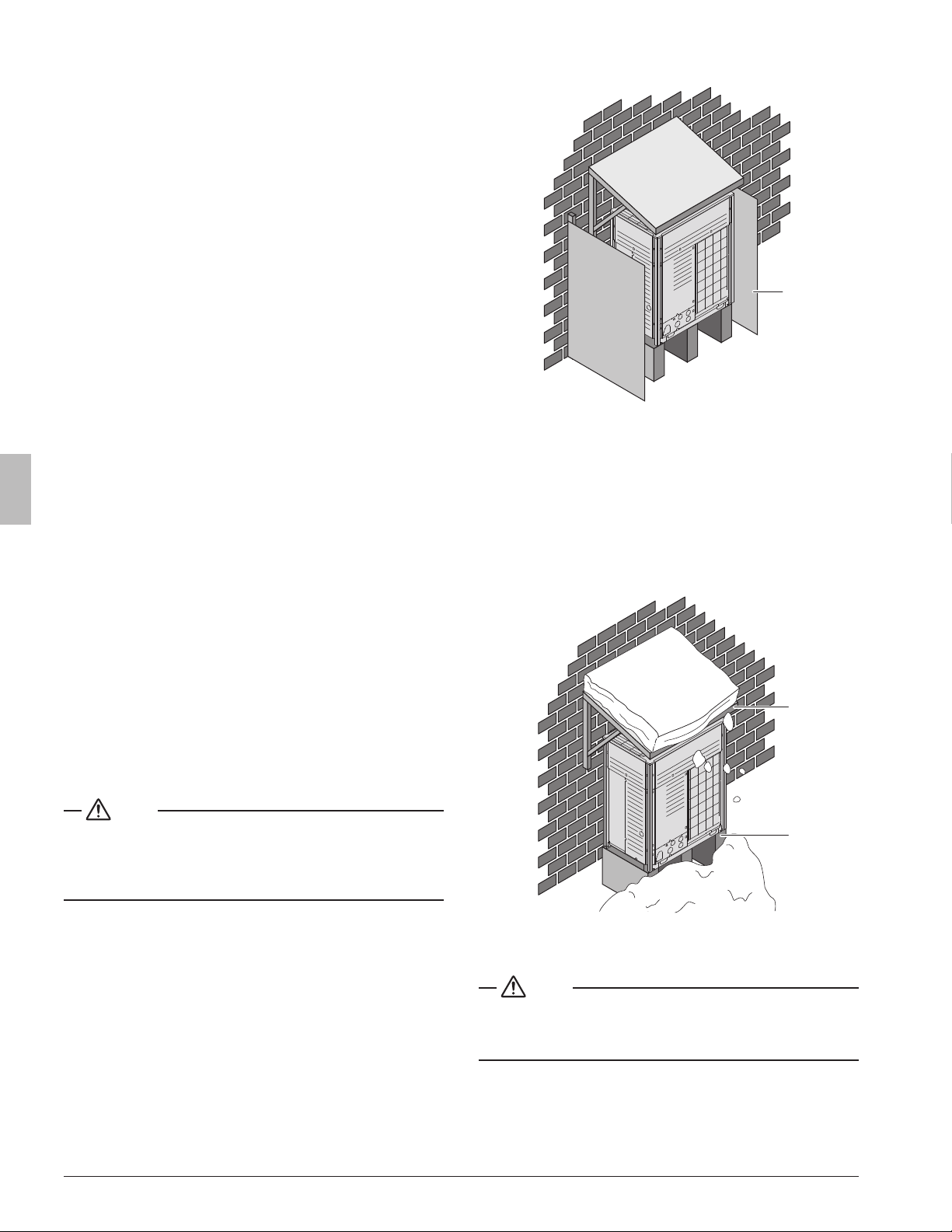
To prevent exposure to wind and snow, install a bafe plates on the air
side of the outdoor unit (see 5.2. Service space for space requirement):
1
1 Bafe plates
In heavy snowfall areas it is very important to select an installation
site where the snow will not affect the unit. Additionally, installation of
a snow guard is recommended. When installing the unit in a location
where there is heavy snowfall, remove the coil guards to prevent snow
from accumulating on the ns.
If lateral snowfall is possible, make sure that the heat exchanger coil
is not affected by the snow (if necessary construct a lateral canopy).
Install the outdoor unit so that the bottom frame is at least 19-11/16 in.
(500 mm) above predicted snowfall levels.
1
2
1 Construct a large canopy.
2 Construct a pedestal.
NOTE
When operating the unit in a low outdoor ambient temperature with
high humidity conditions, make sure to take precautions to keep the
drain holes of the unit free.
63P477778-7G English
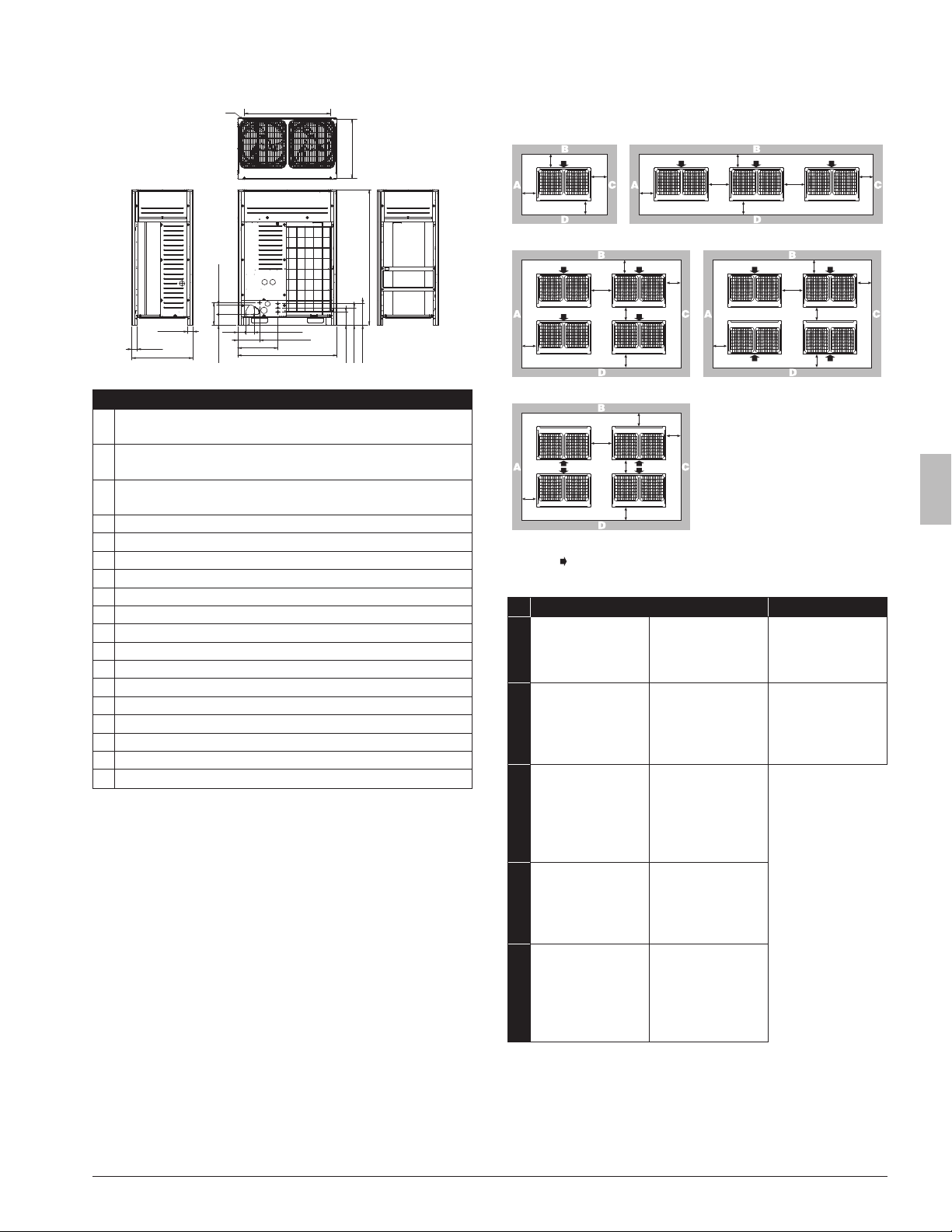
5. Dimensions and service space
5.1. Dimensions of outdoor unit
1
2
3
4
5
6
7
8
9
10
11
12
13
14
1615 17
18
Unit: in. (mm)
REYQ72-168X type
1
Foundation bolt holes
9/16 (15)×7/8 (22.5) oblong holes×4
2
Pitch of foundation bolt holes
42-3/8 (1076)
3
Pitch of foundation bolt holes
28-7/16 to 29 (722 to 737)
4 2-5/8 (67)
5 2-5/8 (67)
6 30-3/16 (767)
7 11-1/8 (282)
8 4-13/16 (122)
9 5-3/16 (132)
10 3-7/8 (98)
11 4-3/16 (107)
12 10-11/16 (272)
13 19-3/4 (502)
14 48-7/8 (1242)
15 6-9/16 (167)
16 8-9/16 (217)
17 10-1/2 (267)
18 66-11/16 (1694)
5.2. Service space
The space around the unit is adequate for servicing and the minimum
space for air inlet and air outlet is available (refer to the gure below
and choose one of the possibilities).
a
b
a
c
d
a
b
a
e
d
e
c
a
b
a
e
d
f
c
a
b
a
e
b
d
c
a
b
a
e
d
f
c
1 2
3
5
4
ABCD Sides along the installation site with obstacles
Suction side
A+B+C+D A+B
1
a≥3/8 (10)
b≥11-3/4 (300)
c≥3/8 (10)
d≥19-5/8 (500)
a≥2 (50)
b≥3-7/8 (100)
c≥2 (50)
d≥19-5/8 (500)
a≥7-7/8 (200)
b≥11-3/4 (300)
2
a≥3/8 (10)
b≥11-3/4 (300)
c≥3/8 (10)
d≥19-5/8 (500)
e≥3/4 (20)
a≥2 (50)
b≥3-7/8 (100)
c≥2 (50)
d≥19-5/8 (500)
e≥3-7/8 (100)
a≥7-7/8 (200)
b≥11-3/4 (300)
e≥15-3/4 (400)
3
a≥3/8 (10)
b≥11-3/4 (300)
c≥3/8 (10)
d≥19-5/8 (500)
e≥3/4 (20)
f≥23-5/8 (100)
a≥2 (50)
b≥3-7/8 (100)
c≥2 (50)
d≥19-5/8 (500)
e≥3-7/8 (100)
f≥19-5/8 (500)
Unit: in.(mm)
4
a≥3/8 (10)
b≥11-3/4 (300)
c≥3/8 (10)
d≥19-5/8 (500)
e≥3/4 (20)
a≥2 (50)
b≥3-7/8 (100)
c≥2 (50)
d≥19-5/8 (500)
e≥3-7/8 (100)
5
a≥3/8 (10)
b≥19-5/8 (500)
c≥3/8 (10)
d≥19-5/8 (500)
e≥3/4 (20)
f≥35-7/16 (900)
a≥2 (50)
b≥19-5/8 (500)
c≥2 (50)
d≥19-5/8 (500)
e≥3-7/8 (100)
f≥23-5/8 (600)
7 3P477778-7G English
h2
a
<Front side> <Suction side>
b +
h2
2
or more
Service
space
h1
2
or more
h1
b
+
a 59 in. (1500 mm)
b 19-5/8 in. (500 mm)
• In case of an installation site where sides A+B+C+D have obsta-
cles, the wall heights of sides A+C have no impact on service space
dimensions. Refer to the foregoing gure for impact of wall heights
of sides B+D on service space dimensions.
• In case of an installation site where only the sides A+B have ob-
stacles, the wall heights have no inuence on any indicated service
space dimensions.
INFORMATION
• Please secure enough space in front of the outdoor unit for on-site
installation of the refrigerant piping.
• The service space dimensions in above gure are based on cooling
operation at 95°F (35°C) ambient temperature (standard condi-
tions).
• If the design outdoor temperature exceeds 95°F (35°C) or the
heat load exceeds maximum capacity in all the outdoor unit, take
an even large space on the intake shown in gure in 5.2. Service
space.
• If installing snow guard (eld supply), please incorporate the dimen-
sions of the snow guard into the unit’s outer dimensions in order to
calculate the necessary amount of space.
• In places with low winter temperatures that may freeze the waste
water created by defrosting during heating operation, please leave
enough space between the bottom frame of the outdoor unit and its
base. (19-11/16 in. (500 mm) to 40 in. (1000 mm) of space is recom-
mended.)
INFORMATION
Further specications can be found in the Engineering Data Book.
6. Inspecting, handling and unpacking the unit
6.1. Inspection
At delivery, the unit must be checked and any damage must be re-
ported immediately to the carrier’s claims agent.
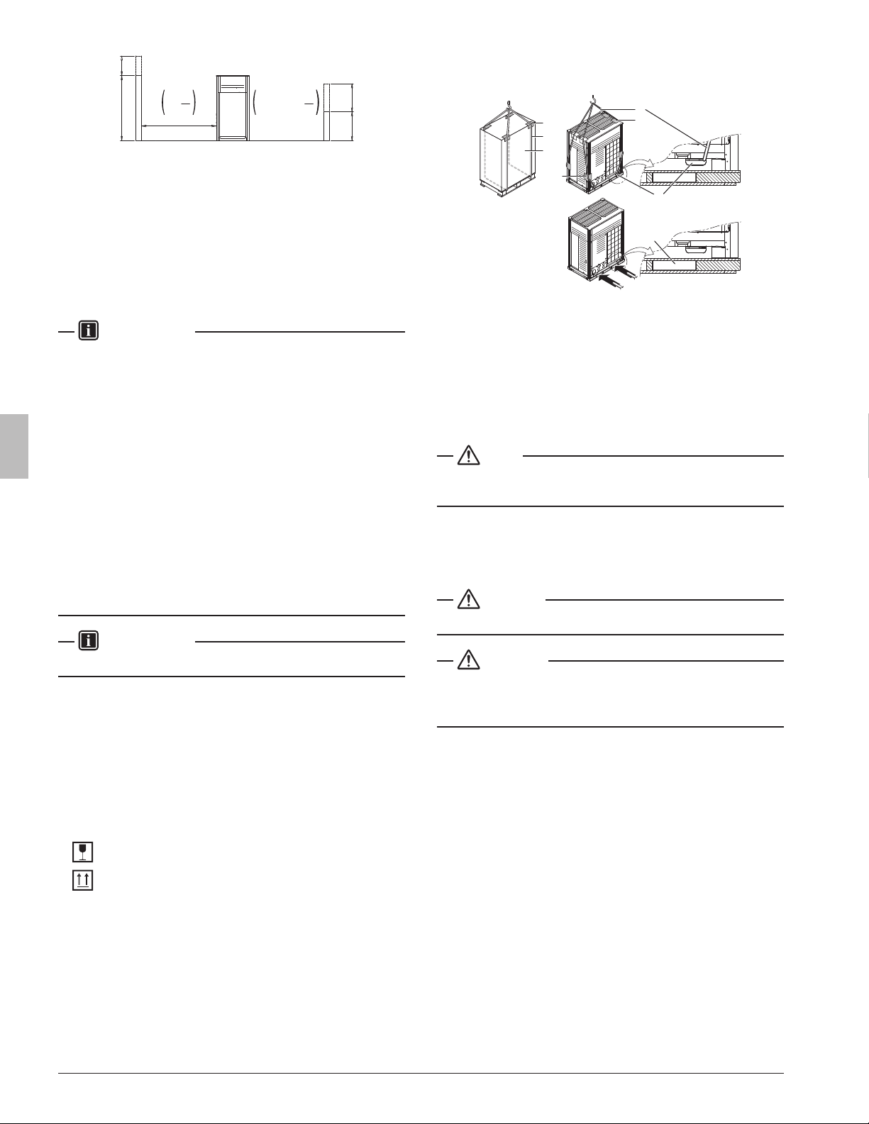
6.2. Handling
1 When handling the unit, take into account the following:
Fragile, handle the unit with care.
Keep the unit upright in order to avoid compressor damage.
2 Choose beforehand the path along which the unit is to be brought
in.
3 Bring the unit as close as possible to its nal installation position in
its original package to prevent damage during transport.
4
4
2
2
4
3
1
3
1 Packaging material
2 Belt sling
3 Opening
4 Protector
4 Lift the unit preferably with a crane and 2 belts of at least 27 ft.
(8 m) long as shown in the gure above.
Always use protectors to prevent belt damage and pay attention to
the position of the unit’s center of gravity.
NOTE
Use a belt sling of ≤3/4 in. (20 mm) wide that adequately bears the
weight of the unit.
A forklift can only be used for transport as long as the unit remains on
its pallet as shown above.
6.3. Unpacking
CAUTION
To avoid injury, do not touch the air inlet or aluminum ns of the unit.
WARNING
Tear apart and throw away plastic packaging bags so that children will
not play with them. Children playing with plastic bags face danger of
death by suffocation.
1 Remove the unit from its packing material.
Take care not to damage the unit when unpacking.
2 Remove the 4 bolts xing the unit to its pallet.
3 Make sure that all accessories as mentioned in 2.1. Accessories
supplied with this unit on page3 are available in the unit.
83P477778-7G English
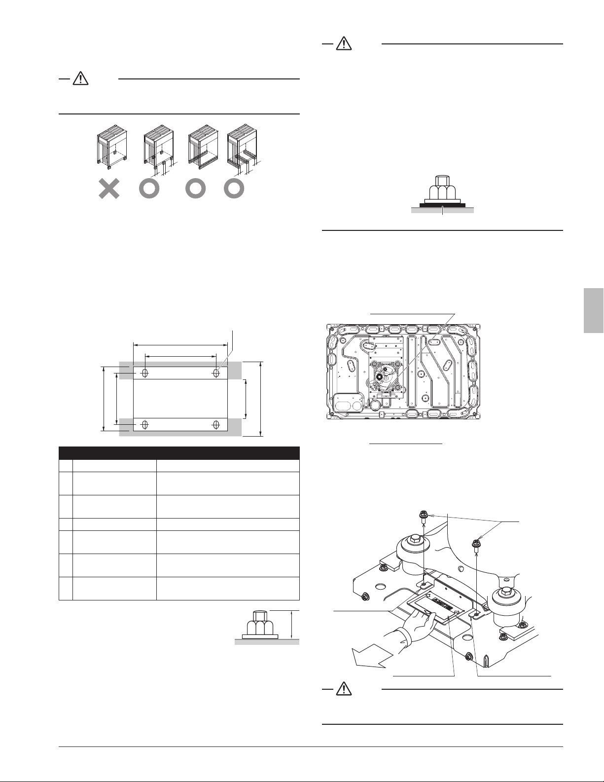
6.4. Installing the unit
Make sure the unit is installed level on a sufciently strong base to
prevent vibration and noise.
NOTE
When the installation height of the unit needs to be increased, do not
use stands to only support the corners.
A
A
A
A
A
A
A
≥3-7/8 in. (100 mm)
X Not allowed
O Allowed
• The height of the foundation must be at least 5-7/8 in. (150 mm )
from the oor.
In heavy snowfall areas, this height should be increased, depending
on the installation place and condition.
• The unit must be installed on a solid longitudinal foundation (steel
beam frame or concrete) and make sure the base under the unit is
larger than the gray marked area.
3
4
2
5
6
7
1
Dimensionsforabovegure
1 Hole for foundation bolt
f9/16 in. (15 mm) dia: 4 positions
2
2 Inner dimension of
the base
24-7/8 in. (631 mm)
3
Distance between
foundation bolt holes
29 in. (729 mm)
4 Width of unit 30-3/16 in. (767 mm)
5
Outer dimension of the
base
≥30-3/16 in. (767 mm)
6
Longitudinal foundation
dimension
48-7/8 in. (1242 mm)
7
Distance between
foundation bolt holes
42-3/8 in. (1076 mm)
• Fasten the unit in place using 4 foundation bolts
7/16 in. (M12). It is best to screw in the founda-
tion bolts until their length remains 13/16 in. (20
mm) above the foundation surface.
A
A=13/16 in. (20 mm)
NOTE
• There are restrictions on the refrigerant pipe connecting order
between outdoor units in the case of the multi system.
See 1.2.2. Outdoor units combinations on page2 for detail.
• When installing on a roof, make sure the roof oor is strong enough
and be sure to waterproof all work.
• Make sure the area around the machine drains properly by setting
up drainage grooves around the foundation.
• Drain water is sometimes discharged from the outdoor unit when it
is running.
• For anti-corrosion type, use nuts with resin washers. If the paint on
nut connections comes off, the anti-corrosion effect may decrease.
Resin washer
6.5. Method for removing shipping plates
The shipping plates installed over the compressor legs for protecting
the unit during transport must be removed. Proceed as shown in the
gure and procedure below. REYQ72-120X does not have the ship-
ping plates.
Shipping plates
Front
REYQ144,168X type
1 Remove bolts (2 pcs) for xing shipping plate.
2 Remove all shipping plates (3 pcs).
3 Be sure to tighten the removed bolts back again.
Shipping plate 3Shipping plate 1
Shipping plate 2
Bolt
NOTE
If the unit is operated with the shipping plates still attached, abnormal
vibration or noise may be generated.
9 3P477778-7G English
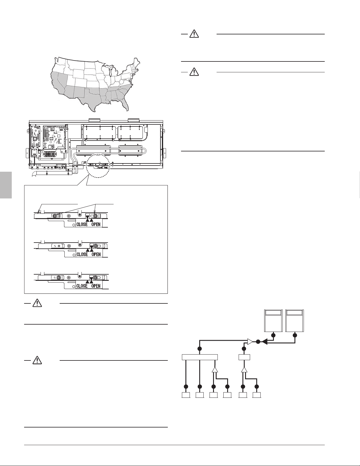
6.6. Method for opening the sliding plate
The sliding plate should be moved to the open position in the following
regions to minimize temperature rise in the main control box: CA,
NV, AZ, NM, OK, TX, AR, LA, MS, AL, TN, GA, NC, SC, FL and Latin
America.
1 Remove the left screw (1 pc.) and loosen the right screw (1 pc.).
SLIDING PLATE
SCREW
2 Move the sliding plate to the right and set the arrow to “OPEN”.
3 Reinstall the left screw and tighten both the left and right screws.
NOTE
Failure to follow the above instructions could lead to premature com-
ponent failure.
7.
Refrigerant pipe size and allowable pipe length
7.1. General information
NOTE
The refrigerant R410A requires strict cautions for keeping the system
clean, dry and tight.
• Clean and dry: foreign materials (including mineral oils or moisture)
should be prevented from getting mixed into the system.
• Tight: R410A does not contain any chlorine, does not destroy
the ozone layer, and does not reduce earth’s protection against
harmful ultraviolet radiation. R410A can contribute slightly to the
greenhouse effect if it is released. Therefore we should take special
attention to check the tightness of the installation.
7.2 . Selection of piping material
NOTE
Piping and other pressure containing parts shall comply with the appli-
cable legislation and shall be suitable for refrigerant. Use phosphoric
acid deoxidized seamless copper for refrigerant.
NOTE
• All eld piping must be installed by a licensed refrigeration techni-
cian and must comply with relevant local and national regulations.
• After piping work is complete, do not under any circumstances open
the stop valve until 9. Field wiring on page18 and 12. Checking of
device and installation conditions on page24 are complete.
• Do not use ux when brazing the refrigerant piping. Use the phos-
phor copper brazing ller metal (B-Cu93P-710/795 : ISO 3677)
which does not require ux. Flux has extremely negative effect on
refrigerant piping systems. For instance, if the chlorine based ux is
used, it will cause pipe corrosion or, in particular, if the ux contains
uorine, it will damage the refrigerant oil.
• Use only pipes which are clean inside and outside and which do not
accumulate harmful sulfur, oxidants, dirt, cutting oils, moisture, or
other contamination. (Foreign materials inside pipes including oils
for fabrication must be 0.14 gr/10 ft. (30 mg/10 m) or less.)
• Use the following items for the refrigerant piping.
Material : Jointless phosphor-deoxidized copper pipe.
Size : See 7.3. Selection of piping size to determine the correct
size.
Thickness : Select a thickness for the refrigerant piping which
complies with national and local laws.
• For piping work, follow the maximum tolerated length, difference in
height, and length after a branch indicated in the 7.5. System piping
(length) limitations on page 11.
• Outdoor unit multi connection piping kit and refrigerant branch kit
(sold separately) are needed for connection of piping between
outdoor units (in case of multi system) and piping branches.
• Use only separately sold items selected specically according to
the outdoor unit multi connection piping kit, the refrigerant branch kit
selection in the 7.4. Selection of refrigerant branch kits on page 10.
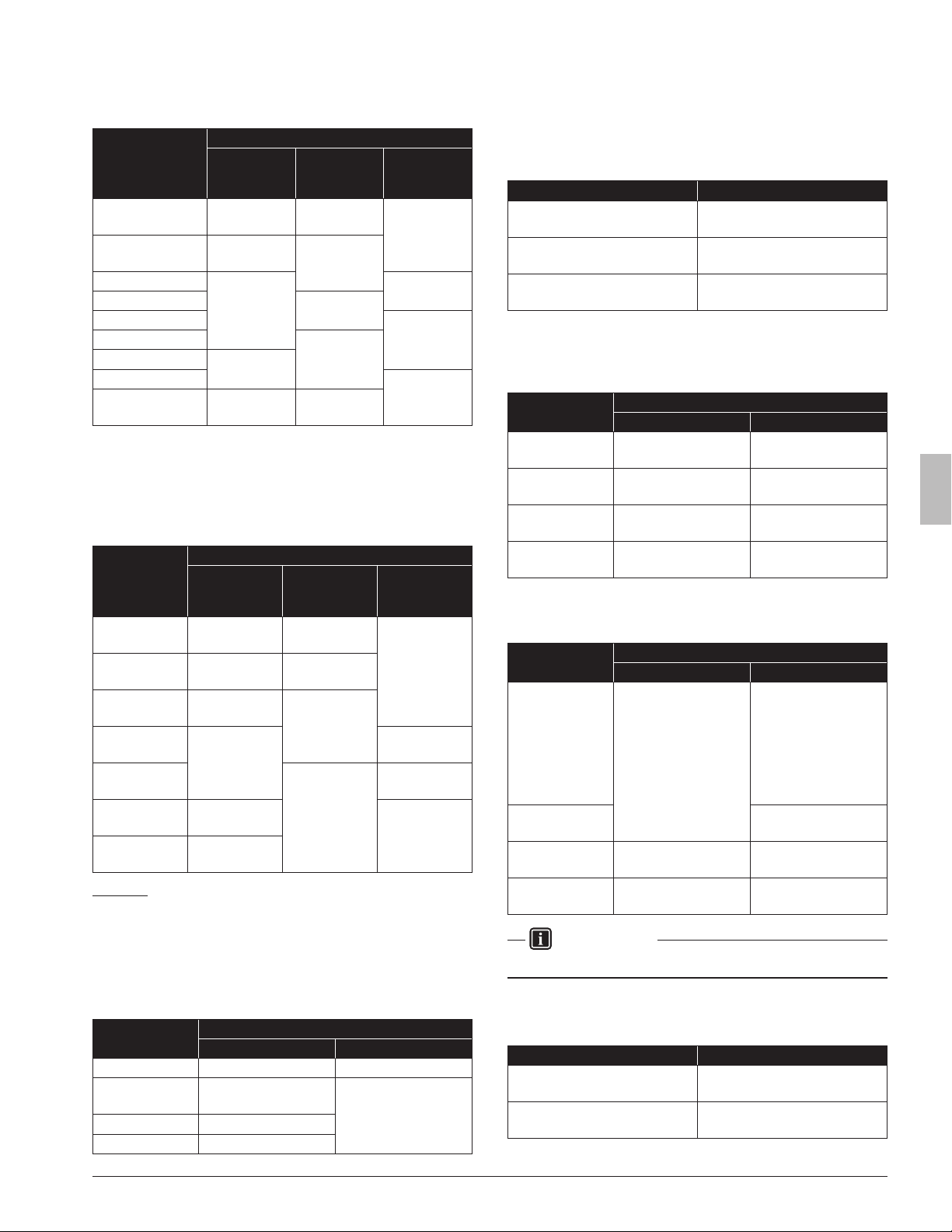
7.3. Selection of piping size
Determine the proper size referring to following tables and reference
gure (only for indication).
A
C
a
D
b
1
2
D
5 6
C
D
b
D
7 8
DD
43
B B
x
1 Multi Branch Selector unit
2 Single Branch Selector unit
3-8 VRV indoor units
a, b Refrigerant branch kits
x Outdoor unit multi connection piping kits
103P477778-7G English
7.3.1. Pipingbetweenoutdoorunitsand(rst)refrigerant
branch kit: A, B
Choose from the following table in accordance with the outdoor unit
total capacity type, connected downstream.
Outdoor unit
capacity type
Piping outer diameter size
Suction gas
pipe
High/low
pressure gas
pipe
Liquid pipe
REYQ72X type
3/4 in.
(19.1 mm)
5/8 in.
(15.9 mm)
3/8 in.
(9.5 mm)
REYQ96X type
7/8 in.
(22.2 mm)
3/4 in.
(19.1 mm)
REYQ120X type
1-1/8 in.
(28.6 mm)
1/2 in.
(12.7 mm)
REYQ144X type
7/8 in.
(22.2 mm)
REYQ168X type
5/8 in.
(15.9 mm)
REYQ192, 216X type
1-1/8 in.
(28.6 mm)
REYQ240X type
1-3/8 in.
(34.9 mm)
REYQ264-336X type
3/4 in.
(19.1 mm)
REYQ360-456X type
1-5/8 in.
(41.3 mm)
1-3/8 in.
(34.9 mm)
7.3. 2 . Piping between refrigerant branch kits or refrigerant
branch kits and Branch Selector units: C
Choose from the following table in accordance with the indoor unit
total capacity, connected downstream. Do not let the connection pip-
ing exceed the refrigerant piping size chosen by the general system
model name.
Indoor unit
capacity index
Piping outer diameter size
Suction gas
pipe
High/low
pressure gas
pipe
Liquid pipe
<54
5/8 in.
(15.9 mm)
1/2 in.
(12.7 mm)
3/8 in.
(9.5 mm)
54≤×<72
3/4 in.
(19.1 mm)
5/8 in.
(15.9 mm)
72≤×<111
7/8 in.
(22.2 mm)
3/4 in.
(19.1 mm)
111≤×<162
1-1/8 in.
(28.6 mm)
1/2 in.
(12.7 mm)
162≤×<230
1-1/8 in.
(28.6 mm)
5/8 in.
(15.9 mm)
230≤×<300
1-3/8 in.
(34.9 mm)
3/4 in.
(19.1 mm)
>300
1-5/8 in.
(41.3 mm)
Example:
Downstream capacity for C = capacity index of (unit 3 + unit 4 + unit 5
+ unit 6)
7.3.3. Piping between refrigerant branch kits or Branch Selec-
tor units and indoor units: D
Pipe size for direct connection to indoor units must be the same as the
connection size of the VRV indoor units.
Indoor unit
capacity index
Piping outer diameter size
Gas pipe Liquid pipe
07, 09, 12, 18 1/2 in. (12.7 mm) 1/4 in. (6.4 mm)
24, 30, 36, 42,
48, 54
5/8 in. (15.9 mm)
3/8 in. (9.5 mm)
72 3/4 in. (19.1 mm)
96 7/8 in. (22.2 mm)
7.4. Selection of refrigerant branch kits
For piping example, refer to 7.3. Selection of piping size on page9.
• When using REFNET joints at the rst branch from the outdoor
units, choose from the following table in accordance with the capac-
ity of the outdoor unit (example: REFNET joint a - see 7.3. Selection
of piping size).
Outdoor unit capacity type Kit name
REYQ72, 96X type
KHRP25A33T9
KHRP25A33TA
REYQ120-216X type
KHRP25M72TU9
KHRP25M72TUA
REYQ240-456X type
KHRP25M73TU9
KHRP25M73TUA
• For REFNET joints other than the rst branch (example REFNET
joint b - see 7.3. Selection of piping size), select the proper branch
kit model based on the total capacity of all indoor units connected
after the refrigerant branch.
Indoor unit
capacity index
Kit name
(for3pipes) (for2pipes)
<72
KHRP25A22T9
KHRP25A22TA
KHRP26A22T9
KHRP26A22TA
72≤×<111
KHRP25A33T9
KHRP25A33TA
KHRP26A33T9
KHRP26A33TA
111≤×<246
KHRP25M72TU9
KHRP25M72TUA
KHRP26M72T9
KHRP26M72TUA
≥246
KHRP25M73TU9
KHRP25M73TUA
KHRP26M73T9
KHRP26M73TUA
• Concerning REFNET headers, choose from the following table in
accordance with the total capacity of all the indoor units connected
after the REFNET header.
Indoor unit
capacity index
Kit name
(for3pipes) (for2pipes)
<72
KHRP25M33H9
KHRP25M33HA
KHRP26M22H9/
KHRP26M22HA:
maximum 4 inddor units
or
KHRP26M33H9/
KHRP26M33HA:
maximum 8 indoor units
72≤×<111
KHRP26M33H9
KHRP26M33HA
111≤×<230
KHRP25M72H9
KHRP25M72HA
KHRP26M72H9
KHRP26M72HA
≥230
KHRP25M73HU9
KHRP25M73HUA
KHRP26M73H9
KHRP26M73HA
INFORMATION
Maximum 8 branches can be connected to a header.
• How to choose an outdoor multi connection piping kit (needed if the
outdoor unit capacity type is 144 or more). Choose from the follow-
ing table in accordance with the number of outdoor units.
Number of outdoor units Branch kit name
2
BHFP26P100U
BHFP26P100UA
3
BHFP26P151U
BHFP26P151UA
11 3P477778-7G English
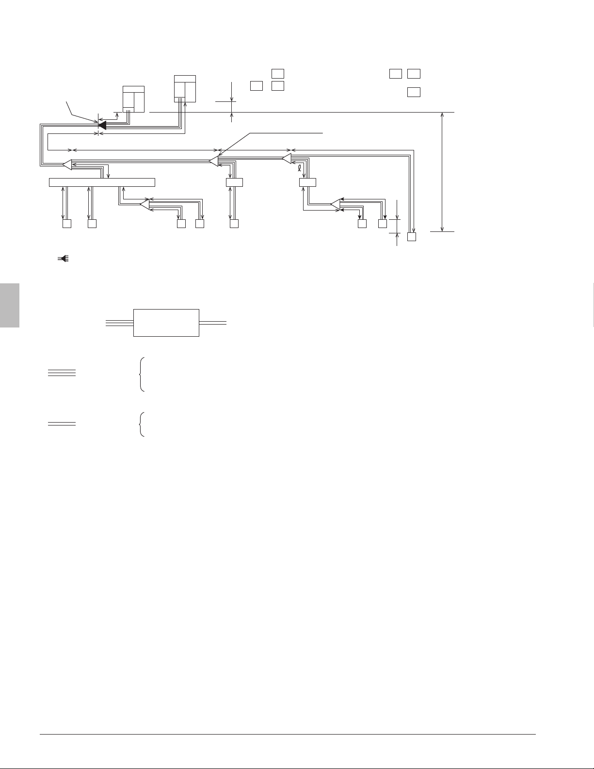
7.5. Systempiping(length)limitations
<Exampleofrefrigerantpiping(8indoorunitsareconnected)>
A
B
C
E
B1 B2 B3
1 2
4 5 6 7
8
3
D
a
b c
d
e f
g
h
i
j
k
m
n
o
p
H1
H3
H2
t
r
: Indoor units (cooling/heating
selectable)
: Branch Selector unit (multi)
: Branch Selector unit (single)
B1
B3B2
-
1 7
: Indoor unit (cooling only)
(*3)
8
REFNET joint (A-E)
,
Outdoor unit
Outdoor unit
First outdoor unit
multi connection
piping kit (*1)
(*1) “ ” represents an outdoor unit multi connection piping kit.
The outdoor unit multi connection piping kit must always be installed horizontally, paying attention to the installation restrictions indicated in
8.Precautionsonrefrigerantpiping on page 14.
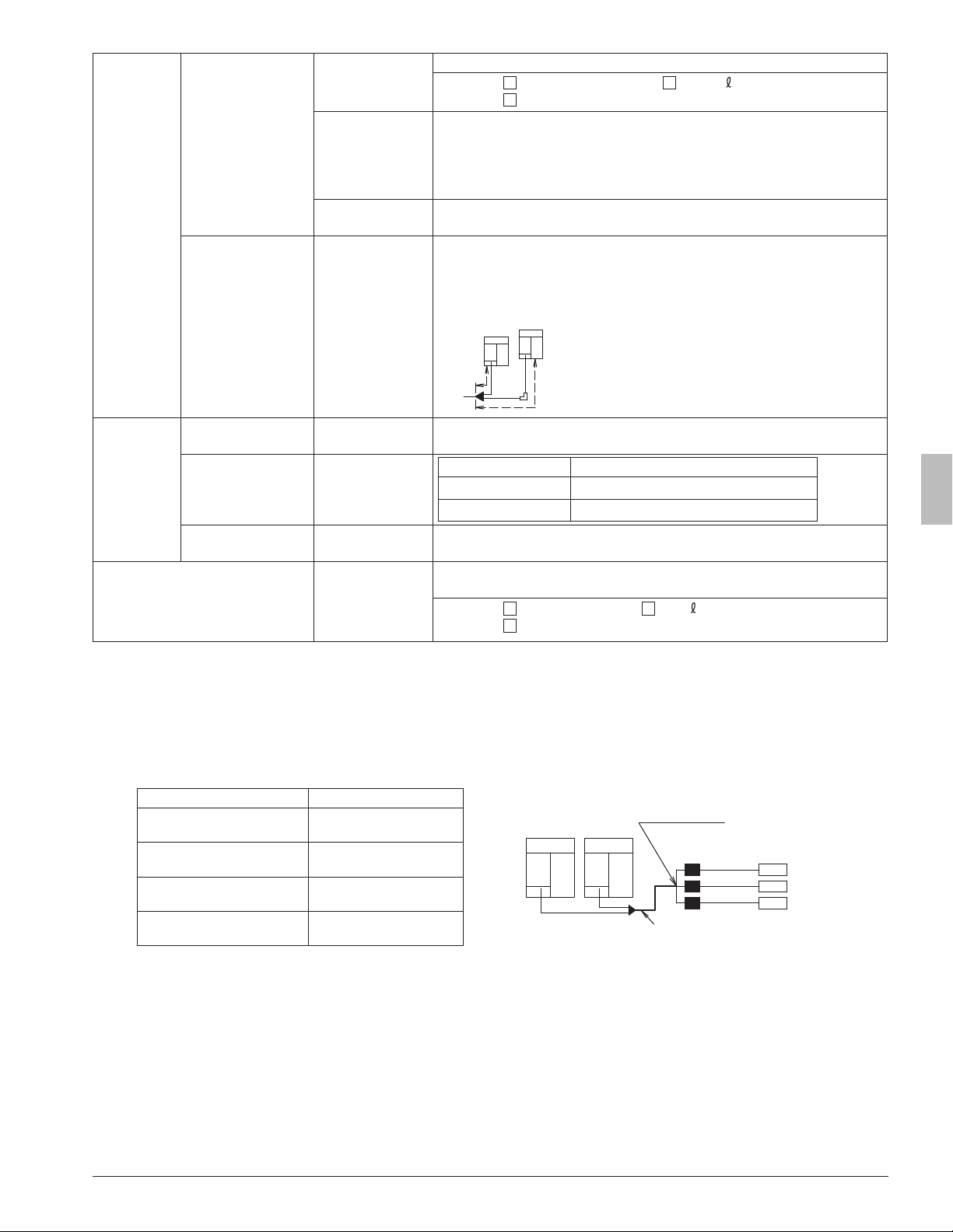
<Exampleofconnection>
Outdoor unit
side
Indoor unit
side
Branch Selector
unit
(1) (2)
(1)PipingfromoutdoorunitstoBranchSelectorunits
Suction gas pipe
High/low pressure gas pipe
Liquid pipe
(3 lines): 3 pipes
(2)PipingfromBranchSelectorunitstotheindoorunits,andfromrefrigerantbranchkitstothecooling-onlyindoorunits(*2)
(2 lines): 2 pipes
(Suction) gas pipe
Liquid pipe
(*2) The 2-line gas pipe that is branched from the 3-line pipe and goes to the cooling-only indoor units should be connected to the suction gas pipe.
(*3) Cooling-only units should make up ≤50% of the total capacity of indoor units.
123P477778-7G English
Maximum
allowable
length
From outdoor unit (*4)
to indoor unit
Actual piping length
Actual piping length from the outdoor unit (*4) to the indoor unit: ≤540 ft. (165 m)
(Example)
4
: a+d+g+i≤540 ft. (165 m),
7
: a+b+c+ +m+o≤540 ft. (165 m),
8
: a+b+c+p≤540 ft. (165 m)
Equivalent length
Equivalent piping length from the outdoor unit (*4) to the indoor unit: ≤623 ft.
(190m) (*6)
(Calculate the equivalent piping length for the REFNET joint as 1.6 ft. (0.5 m),
REFNET header as 3.3 ft. (1 m), BS4
•
6Q54TVJ as 19 ft. (6 m), BS8 to 12Q54TVJ
as 33ft. (10 m), BSQ36
•
60TVJ as 13 ft. (4 m), and BSQ96TVJ as 19 ft. (6 m).)
Total extension
Total actual piping length from the outdoor unit (*4) to all indoor units: ≤ 3280 ft.
(1000 m)
From rst outdoor unit
multi connection pip-
ing kit to outdoor unit
(in a multi system)
Actual piping length
Equivalent length
Actual piping length from the rst outdoor unit multi connection piping kit to the
outdoor unit: ≤33 ft. (10 m)
Equivalent piping length from the rst outdoor unit multi connection piping kit to the
outdoor unit: ≤43 ft. (13 m)
Outdoor unit
t
s
s≤33 ft. (10 m) (equivalent length≤43 ft. (13 m))
t≤33 ft. (10 m) (equivalent length≤43 ft. (13 m))
Allowable
height differ-
ence
From outdoor unit to
indoor unit
Height difference
Height difference between outdoor unit and indoor unit (H1): ≤164 ft. (50 m) (if
outdoor unit is lower than indoor unit, ≤130 ft. (40 m)) (*7)
From indoor unit to
indoor unit
Height difference
From outdoor unit to
outdoor unit
Height difference Height difference between outdoor units (H3): ≤16 ft. (5 m)
Allowable length after branch (*5) Actual piping length
Actual piping length from the rst REFNET joint or REFNET header to indoor
unit: ≤130 ft. (40 m) (*8)
(Example)
4
: d+g+i≤130 ft. (40 m),
7
: b+c+ +m+o≤130 ft. (40 m),
8
: b+c+p≤130 ft. (40 m)
(*4)
In the case of an outdoor units multi system, “outdoor unit” should be read as the “rst outdoor unit multi connection piping kit”, seen from the
indoor units side.
(*5) In the case of a multi Branch Selector unit, it should be read as the “REFNET header”, and the allowable length of piping should be selected.
In the case where only 1 multi Branch Selector unit is included in the system, the actual piping length from each branch points of the multi
Branch Selector unit to each indoor units should be ≤130 ft. (40 m).
(*6) In the case where the equivalent piping length from outdoor units to indoor units ≥295 ft. (90 m), make sure to upsize the liquid pipe of the main
pipe (see the gure below), referring to the table below. (Do not upsize the high/low pressure gas pipe and the suction gas pipe.)
Outdoor unit capacity type Liquid pipe
Main pipe
Upsize the liquid pipe
First refrigerant
branch kit
Branch
Selector
units
Indoor
units
Outdoor units
REYQ72, 96X type
f3/8 in. (9.5 mm) →
f1/2 in. (12.7 mm)
REYQ120, 144X type
f1/2 in. (12.7 mm) →
f5/8 in. (15.9 mm)
REYQ168-240X type
f5/8 in. (15.9 mm) →
f3/4 in. (19.1 mm)
REYQ264-456X type
f3/4 in. (19.1 mm) →
f7/8 in. (22.2 mm)
(*7) It can be extended to ≤295 ft. (90 m) (if outdoor unit is lower than indoor unit, ≤195 ft. (60 m) by eld setting). See [2-49]=Height difference set-
ting on page 34.
Actual piping length X
Height difference between indoor units (H2)
X≤540 ft.
(165 m)
≤49 ft.
(15 m)
X≤390 ft.
(120 m)
≤98 ft.
(30 m)
Loading...