


 Loading...
DAIKIN ROOM AIR CONDITIONER
INSTALLATION MANUAL
R410A Split Series
Español Français English
MODELS
FTXS09LVJU
FTXS12LVJU
CTXS07LVJU
Safety Precautions
•Read these Safety Precautions carefully to ensure correct installation.
•This manual classifies the precautions into DANGER, WARNING and CAUTION. Be sure to follow all the precautions below: they are all important for ensuring safety.
DANGER........... |
Indicates an imminently hazardous situation which, if not avoided, will result in death or serious injury. |
||||
WARNING......... |
Failure to follow any of WARNING is likely to result in such grave consequences as death or serious injury. |
||||
CAUTION.......... |
Failure to follow any of CAUTION may in some cases result in grave consequences. |
||||
• The following safety symbols are used throughout this manual: |
|
||||
|
|
|
|
|
|
Be sure to observe this instruction. |
|
|
Be sure to establish a ground connection. |
Never attempt. |
|
|
|
|
|
|
|
|
|
|
|
|
|
•After completing installation, test the unit to check for installation errors. Give the user adequate instructions concerning the use and cleaning of the unit according to the Operation Manual.
 DANGER
•Refrigerant gas is heavier than air and replaces oxygen. A massive leak could lead to oxygen depletion, especially in basements, and an asphyxiation hazard could occur leading to serious injury or death.
•If the refrigerant gas leaks during installation, ventilate the area immediately.
Refrigerant gas may produce a toxic gas if it comes in contact with fire such as from a fan heater, stove or cooking device. Exposure to this gas could cause severe injury or death.
• After completing the installation work, check that the refrigerant gas does not leak.
Refrigerant gas may produce a toxic gas if it comes in contact with fire such as from a fan heater, stove or cooking device. Exposure to this gas could cause severe injury or death.
•Do not ground units to water pipes, telephone wires or lightning rods because incomplete grounding could cause a severe shock hazard resulting in severe injury or death, and to gas pipes because a gas leak could result in an explosion which could lead to severe injury or death.
•Safely dispose of the packing materials.
Packing materials, such as nails and other metal or wooden parts, may cause stabs or other injuries.Tear apart and throw away plastic packaging bags so that children will not play with them. Children playing with plastic bags face the danger of death by suffocation.
•Do not install unit in an area where flammable materials are present due to risk of explosion resulting in serious injury or death.
•Do not ground units to telephone wires or lightning rods because lightning strikes could cause a severe shock hazard resulting in severe injury or death, and to gas pipes because a gas leak could result in an explosion which could lead to severe injury or death.
 WARNING
• Installation shall be left to the authorized dealer or another trained professional.
Improper installation may cause water leakage, electrical shock, fire, or equipment damage.
• Install the air conditioner according to the instructions given in this manual.
Incomplete installation may cause water leakage, electrical shock, fire or equipment damage.
• Be sure to use the supplied or exact specified installation parts.
Use of other parts may cause the unit to come to fall, water leakage, electrical shock, fire or equipment damage.
• Install the air conditioner on a solid base that is level and can support the weight of the unit.
An inadequate base or incomplete installation may cause injury or equipment damage in the event the unit falls off the base or comes loose.
• Electrical work shall be carried out in accordance with the installation manual and the national, state and local electrical wiring codes.
Insufficient capacity or incomplete electrical work may cause electrical shock, fire or equipment damage.
•Be sure to use a dedicated power circuit. Never use a power supply shared by another appliance. Follow all appropriate electrical codes.
•For wiring, use a wire or cable long enough to cover the entire distance with no splices if possible. Do not use an
extension cord. Do not put other loads on the power supply. Use an only a separate dedicated power circuit.
(Failure to do so may cause abnormal heat, electric shock, fire or equipment damage.)
• Use the specified types of wires for electrical connections between the indoor and outdoor units. Follow all state and local electrical codes.
Firmly clamp the inter-unit wire so their terminals receive no external stresses. Incomplete connections or clamping may cause terminal overheating, fire or equipment damage.
• After connecting all wires be sure to shape the cables so that they do not put undue stress on the electrical covers, panels or terminals.
Install covers over the wires. Incomplete cover installation may cause terminal overheating, electrical shock,fire or equipment damage.
• When installing or relocating the system, be sure to keep the refrigerant circuit free from all substances other than the specified refrigerant (R410A), such as air.
(Any presence of air or other foreign substance in the refrigerant circuit causes an abnormal pressure rise which may result in rupture, resulting in injury.)
English
■English |
1 |
Safety Precautions
 WARNING
• During pump-down, stop the compressor before removing the refrigerant piping.
If the compressor is still running and the stop valve is open during pump-down, air will be sucked in when the refrigerant piping is removed, causing abnormally high pressure which could lead to equipment damage or and personal injury.
• During installation, attach the refrigerant piping securely before running the compressor.
If the refrigerant pipes are not attached and the stop valve is open during pump-down, air will be sucked in when the compressor is run, causing abnormally high pressure which could lead to equipment damage and personal injury.
• Be sure to install a ground fault circuit interrupter breaker.
Failure to install a ground fault circuit interrupter breaker may result in electrically shocks, or fire personal injury.
 CAUTION
• Do not install the air conditioner where gas leakage would be exposed to open flames.
If the gas leaks and builds up around the unit, it may catch fire.
•Establish drain piping according to the instructions of this manual. Inadequate piping may cause water damage.
•Tighten the flare nut according to the specified torque. A torque wrench should be used.
If the flare nut is tightened too much, the flare nut may crack over time and cause refrigerant leakage.
• Do not touch the heat exchanger fins.
Improper handling may result in injury.
• Be very careful about product transportation.
Some products use PP bands for packaging. Do not use any PP bands for a means of transportation. It is dangerous.
• Electrical work must be performed in accordance with the NEC/CEC by authorized personnel only.
Accessories
|
Indoor unit |
A – L , |
|
|
|
|
|
|
|
|
|
|
A |
Mounting plate |
|
E |
Remote controller holder |
|
1 |
|
J |
Tube |
|
|
1 |
|
|
||||||||
|
B Mounting plate fixing screw |
5 |
F |
Fixing screw for remote controller |
|
2 |
|
K |
Operation manual |
||
|
|
3/16” × 1” (M4 × 25mm) |
|
|
holder 1/8” × 13/16” (M3 × 20mm) |
|
|
|
|
|
|
|
C |
Titanium apatite photocatalytic |
2 |
G |
Dry battery AAA. LR03 |
|
2 |
|
L |
Installation manual |
|
|
|
air-purifying filter |
|
|
(alkaline) |
|
|
|
|
|
|
|
D |
Wireless remote controller |
1 |
H |
Indoor unit fixing screw |
|
2 |
|
|
|
|
|
|
3/16” × 1/2” (M4 × 12mm) |
|
|
|
|
|||||
|
|
|
|
|
|
|
|
|
|
|
|
|
|
|
|
|
|
|
|
|
|
|
|
1
1
1
Choosing an Installation Site
• Before choosing the installation site, obtain user approval.
1. Indoor unit
•The indoor unit should be sited in a place where:
1)the restrictions on installation specified in the indoor unit installation drawings are met,
2)both air inlet and air outlet have clear paths met,
3)the unit is not in the path of direct sunlight,
4)the unit is away from the source of heat or steam,
5)there is no source of machine oil vapour (this may shorten indoor unit life),
6)cool (warm) air is circulated throughout the room,
7)the unit is away from electronic ignition type fluorescent lamps (inverter or rapid start type) as they may shorten the remote controller range,
8)the unit is at least 3.5ft (1m) away from any television or radio set (unit may cause interference with the picture or sound),
9)install at the recommended height 6ft (1.8m),
10)no laundry equipment is located in the space.
2.Wireless remote controller
1)Turn on all the fluorescent lamps in the room, if any, and find the site where remote control signals are properly received by the indoor unit (within 23ft/7m).
2 |
■English |

Indoor Unit Installation Drawings
A Mounting plate
B Mounting plate fixing screw
3/16” × 1” (M4 × 25mm)
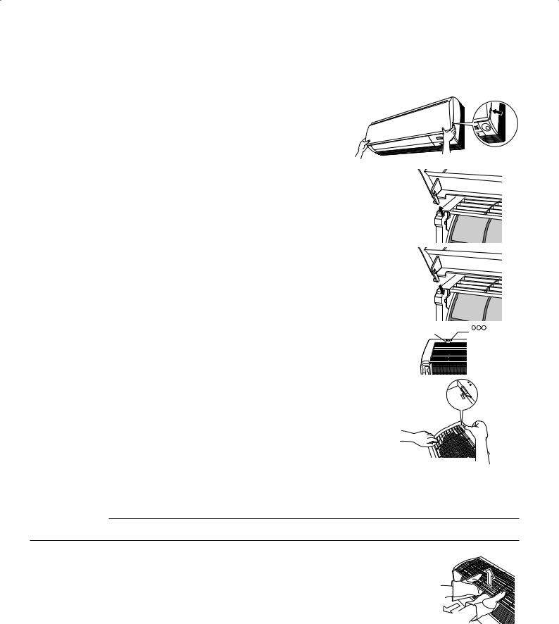
How to attach the indoor unit |
|
|
A Mounting |
Hook the claws of the bottom frame |
|
|
|
|
|
plate |
|
to the mounting plate. |
|
|
|
|
|
|
|
If the claws are difficult to hook, |
|
|
|
remove the front grille. |
|
|
Clip |
|
|
|
|
How to remove the indoor unit |
|
|
|
Push up the marked area (at the |
|
|
|
lower part of the front grille) to |
|
Bottom |
|
release the claws. If it is difficult to |
|
Mark (rear side) |
|
Front grille |
frame |
||
release, remove the front grille. |
|
|
|
|
|
|
The mounting plate should be installed on a wall which can support the weight of the indoor unit.
1-3/16” (30mm)
or more from ceiling
Front panel |
Caulk |
|
pipe hole |
|
gap |
|
with putty. |
1-15/16” (50mm) |
|
or more from walls |
|
(on both sides) |
|
Air filters |
|
|
|
INTELLIGENT EYE |
|
|
sensor |
|
|
3/16” × 5/8” |
|
|
(M4 × 16mm) |
|
|
Service lid |
|
|
Opening service lid |
|
|
Service lid is opening/closing type. |
|
|
Opening method |
C Titanium apatite photocatalytic |
1) Remove the service lid screw. |
|
2) Pull out the service lid diagonally |
||
air purifying filter (2 pcs) |
down in the direction of the arrow. |
|
|
Titanium apatite |
3) Pull down. |
|
|
|
|
photocatalytic |
|
|
air-purifying filter |
|
Filter frame |
|
|
|
|
D |
|
|
Wireless |
Tab |
Air filter |
remote |
controller |
||
|
|
F Fixing screw for remote |
|
|
controller holder |
|
|
1/8” × 13/16” (M3 × 20mm) |
Cut thermal insulation pipe to an appropriate length and wrap it with tape, making sure that no gap is left in the insulation pipe’s cut line.
Wrap the thermal insulation pipe with the finishing tape  from bottom to top.
Before screwing the remote controller holder to the wall, make sure that control signals are properly received by indoor unit.
E Remote
controller holder
INTELLIGENT EYE sensor
 CAUTION
• Do not hit or forcefully push the INTELLIGENT EYE sensor.This can lead to damage and malfunction.
• Do not place large objects near the sensor. Also keep heating units or humidifiers outside the sensor’s detection area.
English
■English |
3 |
Preparation before Installation
1. Removing and installing front panel
•Removal method
Hook fingers on the tabs on the left and right of the main body, and open until the panel stops. Slide the front panel sideways to disengage the rotating shaft.Then pull the front panel toward you to remove it.
•Installation method
Align the tabs of the front panel with the grooves, and push all the way in. Then close slowly. Push the center of the lower surface of the panel firmly to engage the tabs.
2.Removing and installing front grille
•Removal method
1)Remove front panel to remove the air filter.
2)Remove 2 screws from the front grille.
3)In front of the mark of the front grille, there are 3 upper hooks. Lightly pull the front grille toward you with one hand, and push down on the hooks with the fingers of your other hand.
Push the rotating shaft of the front panel into the groove.
Upper hook |
mark area |
|
(3 locations) |
||
|
 Upper hook Push
down.
When there is no work space because the unit is close to ceiling
 CAUTION
•Be sure to wear protection gloves.
Place both hands under the center of the front grille, and while pushing up, pull it toward you.
• Installation method
1)Install the front grille and firmly engage the upper hooks (3 locations).
2)Install 2 screws of the front grille.
3)Install the air filter and then mount the front panel.
1) Push up.
2) Pull toward you.
4 |
■English |
Loading...