


 Loading...
RDUH11-063
Failure diagnosis tool for ZEAS_A type
Digital Pressure Gauge Kit
BHGP26A1(E)(H)
Connected model
ZEAS (A type)
LRLEQ5AY1(E), LRLEQ6AY1(E), LRLEQ8AY1(E), LRLEQ10AY1(E), LRLEQ12AY1(E), LRLEQ15AY1(E), LRLEQ20AY1(E) LRMEQ5AY1(E), LRMEQ6AY1(E), LRMEQ8AY1(E), LRMEQ10AY1(E), LRMEQ12AY1(E), LRMEQ15AY1(E), LRMEQ20AY1(E)
Contents
1. |
Preparation before Connection of |
|
|
|
Digital Pressure Gauge Kit............................................ |
2 |
|
2. |
Overview of Product ...................................................... |
2 |
|
3. |
Connection Drawing ...................................................... |
4 |
|
4. |
Display Item and Method of Operation ........................ |
7 |
|
|
4.1 |
Normal ............................................................................ |
7 |
|
4.2 |
Abnormal......................................................................... |
7 |
|
4.3 |
Manual Operation Display 1............................................ |
8 |
|
4.4 |
Manual Operation Display 2.......................................... |
13 |
5. |
Service Diagnosis ........................................................ |
15 |
|
6. |
The Entire Flow ............................................................ |
16 |
|
1
1. Preparation before Connection of Digital Pressure Gauge Kit
When the Digital Pressure Gauge Kit is connected to the outdoor unit, please confirm the software version of control PCB of ZEAS and you need to change the software if necessary.
Please refer to the manual of software writing delivered.
Check the Software of Condensing Unit
zCondensing unit: If ver. 91 or earlier, please update the software ver. 93 or later.
zCondensing unit: ver. 93 and later...You do not need to change the software.
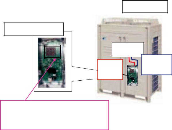
2.Overview of Product
Communicated image
Condensing Unit
Digital Pressure Gauge Kit
Control PCB
Communication Power line
supply line
7 segment display
Pressure and temperature, detail of running data,
Error code of outdoor unit, software version.
Power supply line and communication line are included with BHGP26A1.
2
Specification of Digital Pressure Gauge Kit
Outdoor Temp. range |
–20°C~65°C |
||
Power supply |
|
AC200-240V (+10%, –15%) 50/60Hz |
|
Dimensions |
|
Height (mm) |
268 |
|
|
Width (mm) |
286 |
|
|
Depth (mm) |
47.5 |
Casing |
|
Pressure gauge box main |
Hot-dip zinc-coated steel sheets |
|
|
body |
|
|
|
|
|
|
|
Pressure gauge (cover) |
Metacrylate resin |
Mass |
|
1.8kg |
|
Location |
|
Inside casing of outdoor unit |
|
|
|
|
|
3

3. Connection Drawing
Wiring drawing
Bind the power supply line with a clamp together with the line connected to the outdoor unit.
Insert the power supply line into a wire clip together with the line connected to the outdoor unit.
Section B
Bundle the redundant length portion so that the power supply line or ground wire will not come in contact with the conduit.
Digital Pressure
Gauge Assembly
Ground wire |
|
Power supply line |
Communication |
line |
On-site ground |
Power supply |
terminal |
line |
Bind the power |
|
supply line and |
|
ground wire with |
|
a clamp together |
|
with the line |
|
connected to the |
Ground wire |
outdoor unit. |
Section B detail view
Insert the communication line into a wire clip together with the line connected to the outdoor unit.
Bind the communication line with a clamp together with the line connected to the outdoor unit.
Section A
Bind the communication line with a clamp together with the line connected to the outdoor unit.
Thermistor
Bind the internal wires with the large-sized clamp so that the wires will not come in contact with the thermistor.
20 mm max.
Section A detail view
Be careful not to tense the wire.
Label pasting drawing
|
Discharge pressure display |
Gauge window |
Gauge window |
label |
label |
DISCHARGE
SUCTION
Suction pressure |
|
display |
Resin bush |
C: 2P190979
4
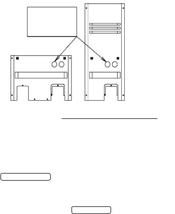
Punch out the knock hole on the left-hand side.
Knock hole on the front panel
Connection drawing
1.Turn the outdoor unit power OFF.
2.Remove the front panel. (If the model has two front panels (i.e., one each on the left-hand side and righthand side), remove the panel on the right-hand side only.)
3.Remove the lid of the electrical box.
4. |
Refer to the Installation drawing and mount the Digital Pressure Gauge Assembly to the panel on the right- |
|
hand side. |
|
[Parts used: Digital Pressure Gauge Assembly: 1, M5×12 screw: 2] |
5. |
Secure the ground wire to the electrical box with a screw. |
|
Refer to section B (detail view) in the Wiring drawing for the screwing position. |
|
[Parts used: M4×12 screw: 1] |
6.Connect the power supply line and communication line of the Digital Pressure Gauge Assembly to the control PCB (A1P) in the electrical box.
•Power supply line: Connector (white) • X77A
•Communication line: Connector (blue) • X27A
At that time, wire the communication line behind the Digital Pressure Gauge Assembly. (Refer to section A (detail view) in the  .)
.)
7. After connecting the power supply line, communication line, and ground wire, secure the wiring path according to the  .
.
[Parts used: Clamps: small 6, large 1]
8.Mount the lid of the electrical box.
9.Punch out the knock hole with a diameter of 70 mm on the front panel. (Refer to the mounting dimensions on the upper right-hand side.)
10.Attach the resin bush to the knock hole on the front panel. [Parts used: Resin bush: 1]
11.Mount the front panel.
12.On completion of installation, turn the outdoor unit power ON and make sure that pressures are displayed normally.
When figures appear in the discharge pressure display and suction pressure indicate, the product is working normally.
(Pressure is indicated in the operation switch "OFF or ON" of outdoor unit.) Abnormal upper section: Error code, Abnormal lower section: LP Abnormal display case: Please refer to the service diagnosis P.15
C:2P190979
5
Loading...