


Daikin JEHCCU-CL1, JEHCCU-CM1, JEHCCU-CM3, JEHSCU-CL3, JEHSCU-CM1 User manual
...Installation Manual
Operation Manual
(Original Instruction)
Reciprocating condensing unit |
Scroll condensing unit |
|
for medium temperature application |
for medium temperature application |
|
Series 1 |
Series 2 |
|
JEHCCU0040CM1 |
JEHSCU0200CM1 |
|
JEHCCU0050CM1 |
JEHSCU0200CM3 |
|
JEHCCU0051CM1 |
JEHSCU0250CM1 |
|
JEHCCU0063CM1 |
JEHSCU0250CM3 |
|
JEHCCU0067CM1 |
JEHSCU0300CM1 |
|
JEHCCU0077CM1 |
JEHSCU0300CM3 |
|
JEHCCU0095CM1 |
JEHSCU0350CM3 |
|
JEHCCU0100CM1 |
|
|
JEHCCU0113CM1 |
Series 3 |
|
|
JEHSCU0400CM3 |
|
Series 2 |
JEHSCU0500CM3 |
|
JEHCCU0140CM1 |
JEHSCU0600CM3 |
|
JEHCCU0140CM3 |
JEHSCU0680CM3 |
|
Reciprocating condensing unit |
Series 4 |
|
for low temperature application |
JEHSCU0800CM3 |
|
Series 1 |
JEHSCU1000CM3 |
|
Scroll condensing unit |
||
JEHCCU0115CL1 |
||
|
for low temperature application |
|
|
Series 2 |
|
|
JEHSCU0200CL3 |
|
|
JEHSCU0300CL3 |
|
|
Series 3 |
|
|
JEHSCU0400CL3 |
|
|
JEHSCU0500CL3 |
|
|
JEHSCU0600CL3 |
|
|
Series 4 |
|
|
JEHSCU0750CL3 |
|
Contents |
|
|
|
|
|
|
|
• |
Ensure the unit received is the correct model for the |
|||
|
|
|
|
|
|
|
|
|
intended application. |
||||
|
|
|
|
|
|
|
|
|
|
|
|
• |
Ensure refrigerant, voltage, are suitable for the |
|
|
|
|
|
|
|
|
|
|
|
|
|
proposed application and environment. |
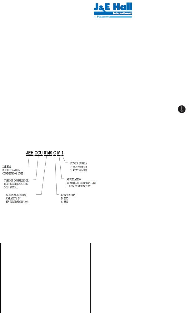
1. |
Nomenclature |
|
|
|
2 |
|
|
|
• |
Installation and maintenance are to be performed only |
|||
|
|
|
|
|
|
|
by qualified personnel who are familiar with local codes |
||||||
2. |
Safety and Health |
|
|
|
2 |
|
|
|
|
and regulations, and experienced with this type of |
|||
|
|
|
|
|
|
|
equipment. |
||||||
3. |
Installation & commissioning |
3 |
|
|
|
• |
The condensing unit is delivered with a nitrogen holding |
||||||
4. |
Decommissioning & Disposal |
6 |
|
|
|
|
charge. |
||||||
|
|
|
• |
The condensing unit contains moving machinery and |
|||||||||
5. |
Checklist |
|
|
|
6 |
|
|
|
|
electrical power hazards. May cause severe injury or |
|||
|
|
|
|
|
|
|
death. Disconnect and shut off power before installation |
||||||
|
|
|
|
|
|
|
|
|
|
|
|
|
|
6. |
Service and Maintenance |
7 |
|
|
|
• |
or service of the equipment. |
||||||
7. |
F gas Regulations |
|
|
|
7 |
|
|
|
Refrigerant release into the atmosphere is illegal. |
||||
|
|
|
|
|
|
|
Proper evacuation, handling and leak testing |
||||||
8. |
Trouble Shooting |
|
|
|
8 |
|
|
|
|
procedures must be observed at all times. |
|||
|
|
|
|
|
|
• |
Condensing unit must be earthed. |
||||||
9. |
Specifications |
|
|
|
9 |
|
|
|
|
Improper earthing may result in electric |
|||
10. |
Outline Drawings |
|
|
|
11 |
|
|
|
|
shocks or fire. |
|||
|
|
|
|
|
|
• |
Be sure to switch off the unit before touching any |
||||||
11. |
Electrical Data |
|
|
|
14 |
|
|
|
|
electrical parts. Touching a live part may result in |
|||
|
|
|
|
|
|
|
electric shocks or fire. |
||||||
12. |
Appendix |
|
|
|
20 |
|
|
|
• |
The electrical covers and condenser fan guard must |
|||
|
|
|
|
|
|
|
|
|
|
|
|
|
remain fitted at all times. |
1. |
Nomenclature |
|
|
|
|
|
|
|
• |
Use of the condensing unit outside of design conditions |
|||
|
|
|
|
|
|
|
|
and application for which units were intended may be |
|||||
|
|
|
|
|
|
|
|
|
|
|
|
|
unsafe and be detrimental to the unit, regardless short |
|
|
|
|
|
|
|
|
|
|
|
|
|
or long term operation. |
|
|
|
|
|
|
|
|
|
|
|
|
• |
The condensing units are not designed to withstand |
|
|
|
|
|
|
|
|
|
|
|
|
|
loads or stresses from other equipment or personnel. |
|
|
|
|
|
|
|
|
|
|
|
Such extraneous loads or stress may cause |
||
|
|
|
|
|
|
|
POWER SUPPLY |
|
|||||
|
|
|
|
|
|
|
1: 230V/50Hz/1PH |
|
|
failure/leak/injury. |
|||
J&E Hall |
|
|
|
|
|||||||||
REFRIGIRATION |
|
|
|
|
3: 400V/50Hz/3PH |
|
• |
In some circumstances, a suction accumulator (not |
|||||
CONDENSING UNIT |
|
|
|
|
|
|
|
|
|
|
supplied) component may be required, it offers |
||
|
|
|
|
|
|
|
|
|
|
|
|
|
protection against refrigerant flood back during |
|
|
|
|
|
|
|
|
|
|
|
|
|
|
TYPE OF COMPRESSOR |
|
|
|
|
|
|
operation. It helps protect against off-cycle migration by |
||||||
|
APPLICATION |
|
|||||||||||
CCU: RECIPROCATING |
|
|
M: MEDIUM TEMPERATURE |
|
adding internal free volume to the low side of the |
||||||||
SCU: SCROLL |
|
|
L: LOW TEMPERATURE |
|
system. |
||||||||
|
|
|
|
|
|
|
|
|
|
|
|
• |
Test must be conducted to ensure the amount of off- |
|
NOMINAL COOLING |
|
GENERATION |
|
|
cycle migration to the compressor does not exceed the |
|||||||
|
CAPACITY IN |
|
B: 2ND |
|
|
|
|
|
compressor’s charge limit. |
||||
|
HP (DEVIDED BY 100) |
|
C: 3RD |
|
|
|
|
• |
Wherever possible the system should be installed to |
||||
|
|
|
|
|
|
|
|
|
|
|
|
||
|
|
|
|
|
|
|
|
|
|
|
|
|
utilize a pump down configuration. For unit Series 1 |
|
|
|
|
|
|
|
|
|
|
|
|
|
JEHCCU040CM1 and JEHCCU0050CM1, it is |
2. |
Safety and Health |
|
|
|
|
|
advisable to connect with thermostat cut off |
||||||
|
|
|
|
|
configuration using the reserved terminal in control box. |
||||||||
|
|
|
|
|
|
|
|
|
|
|
|
• |
After installation, the system should be allowed to run |
|
General Information |
|
|
|
|
|
|
|
|
for 3 – 4 hours. The oil level should be checked after 3 |
|||
|
|
|
|
|
|
|
|
|
– 4 hours run time and topped up as necessary. The oil |
||||
|
|
|
|
|
|
|
|
|
|
|
|
|
level should not be lower than quarter of the |
|
|
|
|
|
|
|
|
|
|
|
|
|
compressor oil sight glass. |
|
|
|
|
|
|
|
|
|
|
|
|
|
|
|
|
|
|
Important Note |
|
|
|
|
|
|
|
|
|
|
Only a qualified refrigeration engineer who is familiar |
|
|
||||||||||
|
with refrigeration systems and components, including all |
|
|
||||||||||
|
controls should perform the installation and start-up of |
|
|
||||||||||
|
the system. To avoid potential injury, use care when |
|
|
||||||||||
|
working around coil surfaces or sharp edges of metal |
|
|
||||||||||
|
cabinets. All piping and electrical wiring should be |
|
|
||||||||||
|
installed in accordance with all applicable codes, |
|
|
||||||||||
|
ordinances and local by-laws. |
|
|
|
|
|
|
|
|
|
|||
|
This appliances is not intended for use by persons |
|
|
||||||||||
|
(including children) with reduced physical, sensory or |
|
|
||||||||||
|
mental capabilities, or lack of experience and |
|
|
||||||||||
|
knowledge, unless they have been given supervision or |
|
|
||||||||||
|
instruction concerning use of the appliance by a person |
|
|
||||||||||
|
responsible for their safety. Children should be |
|
|
||||||||||
|
supervised to ensure that they do |
not play |
with the |
|
2 |
||||||||
|
O-CU06-DEC14-1 |
|
|
|
|
|
|
|
|
||||
|
appliance. |
|
|
|
|
|
|
|
|
|
|||
All specifications are subjected to change by the manufacturer without prior notice. The English text is the original instruction. Other languages are the translations of the original instructions.

3.Installation & Commissioning
3.1Unit site location
•In order to achieve maximum cooling capacity, the installation location for condensing unit should be carefully selected.
•Install the condensing unit in such a way so that hot air distributed by the condensing unit cannot be drawn in again (as in the case of short circuit of hot discharge air). Allow sufficient space for maintenance around the unit.
Wrong ! Correct !
•Ensure that there is no obstruction of air flow into or out of the unit. Remove obstacles which block air intake or discharge.
Correct !
Wrong !
•The location must be well ventilated, so the unit can draw in and distribute plenty of air thus lowering the condensing temperature.
•To optimize the unit running conditions, the condenser coil must be cleaned at regular intervals.
3.2 Installation Clearance
•The installation location should allow sufficient space for air flow and maintenance around the unit.
Air inlet |
|
|
|
Air Discharge |
•To allow sufficient space for doing service or installation.
3.3 Compressor handling
To ensure compressor reliability, the condensing unit and the compressor must not be tilt greater than an angle of 45°.
Otherwise, the compressor can fall from its 3 compressor housing spring, which results in noisy vibrations during operation and possible to breakdown.
Springs to absorb vibrations
3.4 Field Piping
Important Note
Line sizing should only be determined by qualified personnel. All local codes of practice must be observed in the installation of refrigerant piping
To ensure satisfactory operation and performance, the following points should be noted for field piping arrangements,
•Couples one indoor unit with one outdoor condensing unit only.
•Release all the pre-charged nitrogen before pipework connection.
•Connecting pipe size for suction and liquid line must same as attaches to the condensing unit. Correct line sizing will minimize the pressure drop and maintain sufficient gas velocity for proper oil return.
•Pipework routes must be as simple and as short as possible. Avoid low points on pipework where oil can accumulate.
•Use only clean, dehydrated refrigeration grade copper tube with large radius elbows. The piping shall be kept with enough bending radius.
•Braze without over filling to ensure there is no excess solder into the tube.
•To prevent oxidation, blow nitrogen through pipework when brazing.
•Install insulation on all suction lines after pressure test.
•Adequately support all pipe work at a maximum of 2 meter intervals.
•For the condition where the outdoor condensing unit is above the indoor unit, the height difference between units shall be less than 25 m and install oil trap on suction pipe every 4 m height. The suction pipe must always be fitted with U-trap at the bottom.
•For the condition where the outdoor condensing unit is below the indoor unit, the height difference between units shall be less than 4 m. Pipe trap shall be installed upward on outlet of indoor unit (suction pipe).
•The recommended piping length is 25 m or less.
•Additional oil might be required in case field piping is long or with many oil traps. Check the oil level of the
O-CU06-DEC14-1 |
3 |
All specifications are subjected to change by the manufacturer without prior notice. The English text is the original instruction. Other languages are the translations of the original instructions.
compressor to decide to add the oil after minimum 2 hours operation.
•It is recommended as well to install the MOP (Maximum Operation Pressure), expansion valve for medium evaporating temperature units, if the working suction pressure during start procedure especially after defrost cycle, is out of the limit, as refer to the table provided.
Important Note
Ensure that a good quality vacuum pump is used to pull a minimum vacuum of -0.1 barg (250 microns) or less. Ensure that no pressure increase during 1 hour or more after stop vacuuming. If pressure increase, there is moisture or leakage along the pipeline.
|
Recommend compressor working pressure range |
|
3.8 Safety pressure switch settings |
|||||||||
|
Compressor |
|
|
Med Temp |
|
|
Me Temp |
|
Med Temp |
|
||
|
|
|
|
|
|
|
|
|||||
|
ModelCompressor |
|
|
Med Temp |
|
Med Temp |
|
Med Temp |
|
The pressure switch fitted to condensing units with auto |
||
|
ModelAE/CAJ/TAJ |
|
|
MTZ |
|
ZB*KQE |
|
|||||
|
Refrigerant |
|
|
AE/CAJ/TAJ |
R404A |
MTZ |
R407C |
ZB*KQE |
R134a |
reset for low pressure and manual reset for high pressure |
||
|
R404A/R407A/ |
R134a |
R134a |
R404A/R407A/ |
||||||||
|
Refrigerant R407FR404A |
R134a |
R404A |
R134a |
R407C |
R404AR407F R134a |
|
are NOT factory preset. |
||||
|
|
|
|
|
|
|
|
|
|
|
||
|
WorkingWorking Pressure |
|
6.7 – |
.2 – |
7.9 – |
12.5 – |
|
6.6 – |
|
|
||
|
Pressure |
|
|
13.2 - 27.7 |
7.14 - 27.6 6.6 - 22.6 |
|
|
|||||
|
Range High Side, |
6.7 - 15.8 |
13.2 - 27.7 |
7.9 - 22.6 |
12.5 - 29.4 |
22.6 |
|
|
||||
|
Range High |
|
13.2 – 27.7 |
15.8 |
27.7 |
22.6 |
29.4 |
7.14 – 27.6 |
|
|
||
|
Side (barg)(barg) |
|
|
|
|
|
|
|
|
|
|
|
|
Working Pressure |
|
|
|
|
|
|
|
|
|
||
|
Working |
|
|
1.5 - 8.3 |
0.1 - 3.9 |
1.0 -7.2 |
0.6 - 4.7 |
1.4 - 6.6 |
1.98 - 7.14 0.6 - 3.8 |
|
|
|
|
Range Low Side, |
0.6 – |
|
|
||||||||
|
Pressure |
|
1.5 – 8.3 |
0.1 – |
1.0 – |
0.6 – |
1.4 – |
1.98 – 7.14 |
|
|
||
|
Range Low(barg) |
3.9 |
7.2 |
4.7 |
6.6 |
3.8 |
|
|
||||
|
Side, (barg) |
|
|
|
|
|
|
|
|
|
|
|
|
|
|
|
|
|
|
|
|
|
|
|
|
3.5 Pressure testing
•Make sure that both service valves are closed when running a pressure test on field piping, always use an inert, dry gas such as Nitrogen
• |
The pressure differential between the high and low side |
|
|
flare |
|
|
|||
|
shall not higher than below. |
|
|
|
|
|
|||
|
|
|
|
|
|
||||
|
|
|
|
|
|
|
|
|
|
|
|
Compressor |
Pressure differential |
|
|
|
|
|
|
|
|
AE/AJ |
19 barg |
|
|
|
|
|
|
|
|
|
(275 psig) |
|
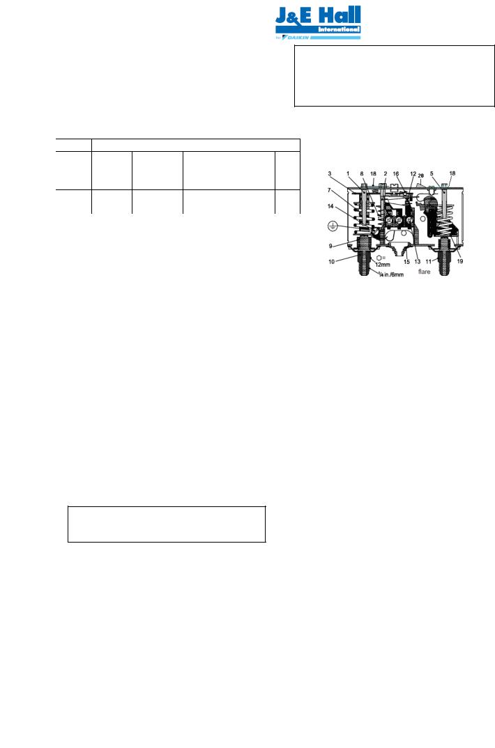
1. |
Low pressure (LP) setting |
12. |
Switch |
|
|
|
MTZ/ZB*KQE |
30 barg |
|
|||||
|
|
|
spindle |
13. |
Terminals |
||||
|
|
|
(435 psig) |
|
2. |
Differential setting spindle, LP |
14. |
Earth terminal |
|
• |
Test pressures shall be as shown follows. |
3. |
Main arm |
15. |
Cable entry |
||||
5. |
High pressure (HP) setting |
16. |
Tumbler |
||||||
|
|
Test pressure |
|
spindle |
18. |
Locking plate |
|||
|
|
High side |
Low side |
|
7. |
Main spring |
19. |
Arm |
|
|
|
28 barg |
19 barg |
|
8. |
Differential spring |
20. |
Manual reset |
|
|
|
(405 psig) |
(275 psig) |
|
9. |
Bellows |
button |
||
• |
If there is pressure drop, check the leakage portion. |
10. LP connection |
|
|
|
||||
|
|
|
|
|
11. HP connection |
|
|
|
|
3.6 Leak detection
•Make sure that all manual valves are open
•Perform a leak test of the system using nitrogen mixed with the refrigerant to be used
•Do not use CFC for leak testing the condensing unit which will be used with HFC refrigerants
•The use of leak testing fluids is not recommended as this may interact with the lubricants own additives
3.7Vacuum - moisture removal
Important Note
Moisture prevents proper functioning of the compressor and the refrigeration system
Air and moisture reduce service life and increase condensing pressure causing abnormally high discharge temperatures likely to destroy the oil’s lubricating properties. The risk of acid formation is also increased by air and moisture and copper plating can be generated in this way. All these phenomena can cause mechanical and electrical failure.
High pressure safety (Manual reset)
The high pressure safety switch is required to protect the compressor from working out of its envelope. The high pressure switch shall set equal or lower than below values depending on the type of refrigerant, application and the ambient condition.
Model |
|
|
|
AE/CAJ/TAJ |
|
|
MTZ/ZB |
|
|
||||||
Refrigerant |
|
|
R404A/ |
R134a |
|
R404A/ |
|
R134a |
|
|
|||||
|
|
|
R407A/ |
|
|
|
R407A/ |
|
|
|
|
|
|||
|
|
|
|
R407F |
|
|
|
R407F |
|
|
|
|
|
||
Cut Out (barg) |
|
27.7 |
|
18 |
|
|
27.7 |
|
18 |
|
|
||||
Cut Out (psig) |
|
402 |
|
261 |
|
|
402 |
|
261 |
|
|
||||
|
|
|
|
|
|
|
|
|
|
|
|
|
|||
Model |
AE/CAJ/TAJ |
|
|
|
|
MTZ |
|
|
|
ZB*KQE |
|||||
Refrigerant |
R404A/ |
|
R134a |
|
R404A |
|
R134a |
R407C |
|
R404A/ |
|
R134a |
|||
R407A/ |
|
|
|
|
R407A/ |
|
|||||||||
|
R407F |
|
|
|
|
|
|
|
|
|
|
R407F |
|
|
|
|
|
|
|
|
|
|
|
|
|
|
|
|
|
||
Application |
M* |
|
M* |
|
M* |
|
|
M* |
M* |
|
M* |
|
M* |
||
|
|
|
|
|
|
|
|
|
|
|
|
|
|
|
|
Cut out (barg) |
1.5 |
|
|
0.5 |
|
1 |
|
0.6 |
1.4 |
|
|
2 |
|
0.6 |
|
|
|
|
|
|
|
|
|
|
|
|
|
|
|
||
Cut out (psig) |
21.8 |
|
|
7.3 |
|
14.5 |
|
8.7 |
20.3 |
|
29 |
|
8.7 |
||
O-CU06-DEC14-1 |
4 |
All specifications are subjected to change by the manufacturer without prior notice. The English text is the original instruction. Other languages are the translations of the original instructions.

O-CU06-DEC14-1 |
5 |
All specifications are subjected to change by the manufacturer without prior notice. The English text is the original instruction. Other languages are the translations of the original instructions.
Low pressure safety (Auto reset)
The low pressure safety switch is recommended to avoid compressor operation at too lower suction pressure and vacuum condition. The low pressure safety cut should never be set below value as shown in the following table.
* M: Medium temperature; L: Low temperature
Low Pressure side range adjusting screw Clockwise: Decrease cut in pressure setting
Anticlockwise: Increase cut in pressure setting
Differential adjusting screw Clockwise: Increase differential pressure setting Anticlockwise:Decrease differential pressure setting
High Pressure side range adjusting screw
Clockwise: Increase cut off Manual reset switch pressure setting
Anticlockwise: Decrease cut off pressure setting
Low pressure |
High pressure |
side connector |
side connector |
|
|
The low pressure cut off pressure is the setting of cut in minus the differential.
Important Note
There must be no more than 10 compressor starts per hour. A higher number reduces the service life of the compressor. If necessary, use an anti-short-cycle timer in the control circuit. Minimum a 2 minute runtime after each start of compressor and a 3 minute idle time after each stop & start are recommended. Only during the pump down cycle may the compressor run for much shorter intervals.
3.9 Fan speed controller setting
The fan speed controller regulates the speed of the condenser’s fan.
It keeps the condensing pressure at a steady level by changing the speed of the fan according to the required condensing pressure.
For model in Series 2 and 4 : Recommended setting for range setting pointer/ range adjusting screw as table below:
Medium Temp
Refrigerant |
|
R404A/R407C/R407F/R407A |
|
R134a |
|
Setting (bar) |
|
19 |
|
Series 2- 13 |
|
|
|
Series 4 -10 |
|||
|
|
|
|
|
|
|
Low Temp |
|
|
|
|
|
Refrigerant |
R404A/R407A/R407C/R407F |
|
||
|
Setting |
JEHR model -19 |
|
||
|
(bar) |
JEHS model - 13 |
|
||
Clockwise: Increase pressure set point
Anticlockwise: Decrease pressure set point
360° = 1 turn Approx. 1.5 barg
Cut off: Fan motor stops when the pressure decreases below the value Pmin.
Note:
F.V.S. = Full Voltage Set Point (pressure setting for maximum speed)
E.P.B. = Effective Proportional Band (6 bar) Pmin = (F.V.S. – 6)
For Series 1 model: Recommended setting for Series 1 model which using pressure switch to on/off fan:
Refrigerant |
R404A/ |
|
R407A/ |
R134a |
|
|
R407F |
|
Setting |
|
|
(bar) |
16 |
10 |
Cut in |
|
|
Setting |
|
|
(bar) |
7 |
7 |
Differential |
|
|
The low pressure cut off pressure is the setting of cut in minus the differential.
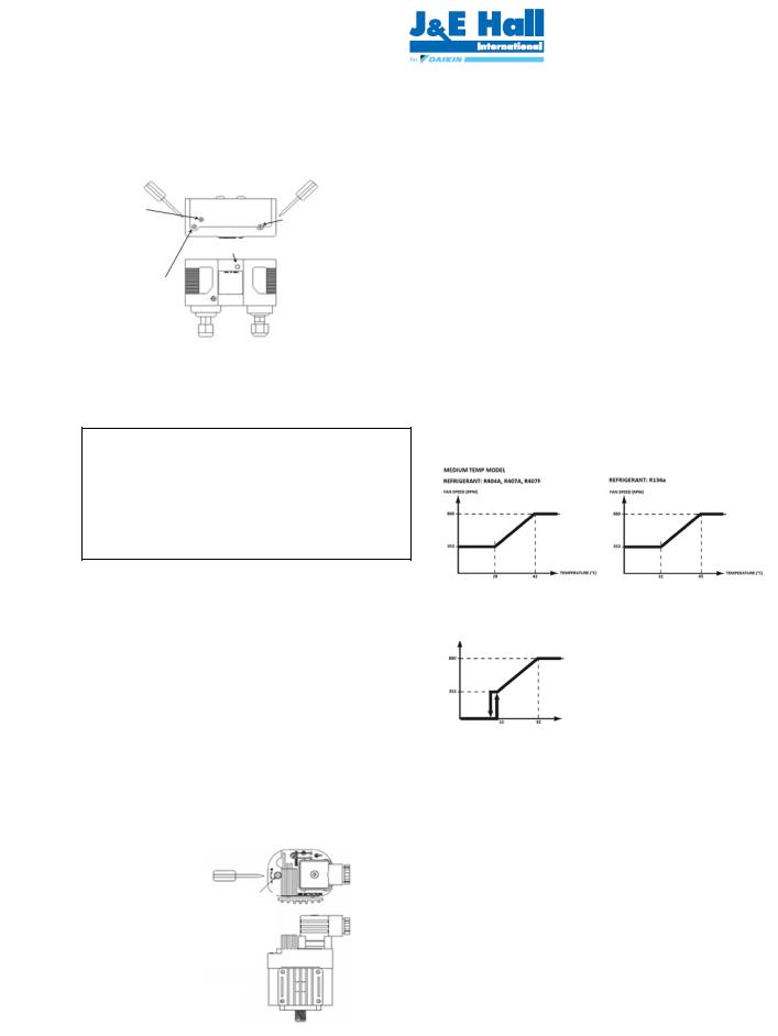
For model in Series 3, the fan speed controller setting as shown below.
MEDIUM TEMP MODEL |
|
|
REFRIGERANT: R404A, R407A, R407F |
|
|
|
REFRIGERANT : R134a |
|
FAN SPEED (RPM) |
|
|
|
FAN SPEED (RPM) |
|
|
|
|
|
|
|
TEMPERATURE (C°) |
|
TEMPERATURE (C°) |
|
|
|
LOW TEMP MODEL
REFRIGERANT: R404A, R407A
FAN SPEED (RPM)
TEMPERATURE (C°)
O-CU06-DEC14-1 |
6 |
All specifications are subjected to change by the manufacturer without prior notice. The English text is the original instruction. Other languages are the translations of the original instructions.
3.10 Commissioning of the Condensing Unit
Please make sure that all manual service valves are fully open when starting the system for the first time. This includes external and internal shut off valves as well as liquid receiver valve in the unit.
The ball valve open position is shown as below:
MAX 150°C
OPEN position
3.11 Compressor electrical wiring
Verification of proper rotation direction is made by observing that suction pressure drops and discharge pressure rises when the compressor is energized. Reverse rotation of a scroll compressor also results in substantially reduced current draw. Suction temperature will be high, discharge temperature will be low and the compressor may generate abnormal noise.
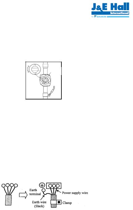
3.12 Earthing of Condensing Unit
Installation of earth wire must be made to earthing screw (labelled with earth label) before connecting the live wires. The earth wire shall be slack as shown in below diagram.
Earth |
|
|
|
|
|
|
Power supply wire |
||||
terminal |
|
|
|||
|
|
|
|
|
|
|
|
|
|
|
|
|
|
|
|
|
|
|
|
|
|
|
|
Eart wire |
Clamp |
||||
(Slack) |
|
|
|
|
|
|
|
|
|
|
|
|
|
|
|
|
|
4.Decommissioning & Disposal
At the end of the unit’s useful life, a suitably qualified engineer should decommission it. The refrigerant and compressor oil are classed as hazardous waste and as such must be reclaimed and disposed of in the correct manner, including completion of waste transfer paperwork. The unit components must be disposed of or recycled as appropriate in the correct manner.
•Check compressor oil level via compressor sight glass, the oil level should not be lower than quarter of sight glass.
•Check the TXV capacity sizing based on indoor unit capacity. Check TXV applicable refrigerant. Check position and condition of the sensing bulb fixing
•Observed the system pressures during the charging and initial operation process.
•Ensure that suction pressure will decrease, discharge pressure will increase. No abnormal noise from the compressor.
•Continue to charge the system until sight glass is clear. Make sure that high pressure is > 14 barg for R404A and > 8 barg for R134a when doing this charge adjustment operation. Continuous flow of clear refrigerant through the sight glass, with perhaps an occasional bubble at very high temperature indicates the refrigerant is at optimum.
•Check the compressor’s discharge and suction pressure, to ensure it is within operating range. Discharge temperature should be within 50 to 90 °C and pressure should be around 15 to 26 barg (for system charged with R404A) and 8 to 16 barg (for system charged with R134a).
•Check the current of condensing unit and ensure it is below the motor circuit breaker setting value.
•Check condenser fan, ensure warm air blowing off the condenser coil.
•Check evaporator blower, ensure it’s discharging cool air.
•Check suction superheat and adjust expansion valve to prevent liquid flood back to the compressor. Recommended 5 to 20 K of suction superheat.
•Do not leave the system unattended until the system has reached its normal operating condition and the oil charge has properly adjusted itself to maintain the proper level in the sight glass.
•Check periodically the compressor performance and all the moving components during the first day of operation.
•Check the liquid line sight glass and expansion valve operation. If there is an indication that the system is low on refrigerant, thoroughly check the system for leaks before adding refrigerant.
|
5. |
Checklist |
• |
Ensure the high low pressure controls are configured |
|
|
properly. |
|
• |
Ensure crankcase heater is energized minimum 12 |
|
|
hours prior to start up and permanently energized. |
|
• |
Check the refrigerant is correct for intended use. |
|
• |
Check all electrical connections. |
|
• |
Check all electrical termination and circuits are correct. |
|
O-CU06-DEC14-1 |
7 |
All specifications are subjected to change by the manufacturer without prior notice. The English text is the original instruction. Other languages are the translations of the original instructions.
 Loading...